
Related Manuals for QSFPTEK S5300-16S8TS4X


Summary of Contents for QSFPTEK S5300-16S8TS4X
- Page 1 S5300-16S8TS4X Quick Start Guide 16-Port Gigabit Ethernet L2++ Switch 16x 1Gb SFP, with 8x Gigabit RJ45/SFP Combo, 4 x 10Gb SFP+ Uplinks, Support Stacking V1.0 www.qsfptek.com v1.0 1 / 11...
- Page 2 S5300 series switches, making them logically regarded as one switch for interconnection and management. We appreciate your decision to select S5300-16S8TS4X. This manual is intended to help you become acquainted with the switch desi gn and provide instructions for implementing the switches into your network.
-
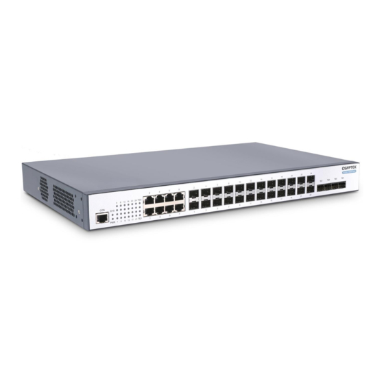
Page 3: Hardware Overview
Front Panel LEDs LEDS Description PWR LED If the switch is powered on, the PWR indicator is on SYS LED If the system is started normally, the SYS indicator flickers SFP LED LINK/ACT SFP+ LED LINK/ACT www.qsfptek.com v1.0 3 / 11... -
Page 4: Installation Requirements
Put the machine box at the place where cool air can blow off the heat inside the machine box. Make sure the machine box is se aled because the opened machine box will reverse the cool air flow. www.qsfptek.com v1.0 4 / 11... - Page 5 Mounting the Switch Connecting the Power 1. Plug the AC power cord to the switch power port on the back rear. 2. Connect the other end of the power cord to a AC power source equipment. www.qsfptek.com v1.0 5 / 11...
- Page 6 2. Connect the other end of the Ethernet cable to the switch RJ45 port. Connecting the SFP Port 1. Insert the SFP module into the SFP port. 2. Plug a fiber patch cable to the SFP transceiver. www.qsfptek.com v1.0 6 / 11...
- Page 7 1. Insert the SFP+ module into the SFP+ port. 2. Plug a fiber patch cable to the SFP+ transceiver. 3. Connect the other end of the fiber to the device that you want to realize data communication. www.qsfptek.com v1.0 7 / 11...
-
Page 8: Connecting The Management Ports
Step 1: Connect your computer to the switch using an Ethernet cable and open a web browser. Step 2: Set the IP address of the computer to 192.168.0.x (where "x" is any number from 2 to 254) and the subnet mask to 255.255.255.0. www.qsfptek.com v1.0 8 / 11... - Page 9 Hyper Terminal on the computer. Step 3: Configure the parameters of the terminal emulation software as follows: 9600 bits per second, 8 data bits, no parity, 1 stop bit, and no flow control www.qsfptek.com v1.0 9 / 11...
-
Page 10: Troubleshooting
If the port of the switch cannot be linked, check whether the cable is correctly connected and whether the peer connection is normal. If the power switch is at the “ON” location, check the power source and the power cable. www.qsfptek.com v1.0... -
Page 11: Support And Other Resources
Product Warranty S5300 series switches are backed by a 5-year limited warranty supported by QSFPTEK. And you are eligible to apply for a return or exchange of your items within 14 days of receiving them. For more details about applying qualifications, please live chat or email sales@qsfptek.com...
Need help?
Do you have a question about the S5300-16S8TS4X and is the answer not in the manual?
Questions and answers