Table of Contents
Advertisement
Quick Links
Advertisement
Table of Contents

Subscribe to Our Youtube Channel
Related Manuals for Pilz PSS u2 P0 F/S EIP2


Summary of Contents for Pilz PSS u2 P0 F/S EIP2
- Page 1 PSS u2 P0 F/S EIP2 Remote I/O system PSS u2 Operating Manual-1005376-EN-01...
- Page 2 Preface This document is the original document. All rights to this documentation are reserved by Pilz GmbH & Co. KG. Copies may be made for the user's internal purposes. Suggestions and comments for improving this documenta- tion will be gratefully received.
-
Page 3: Table Of Contents
FS process image of outputs ....................5.7.3 Restart interlock ........................5.7.4 CIP Safety requirements on the user..................System reaction times ......................Installation ..........................General installation guidelines....................Dimensions in mm ........................Installing the head module......................Operating Manual PSS u2 P0 F/S EIP2 1005376-EN-01... - Page 4 9.1.5 X3, X4 ............................9.1.6 NET............................9.1.7 DIAG ............................9.1.8 ............................Maintenance and repair ......................Technical Details ........................11.1 Safety characteristic data ......................Network data .......................... Order reference ........................13.1 Accessories ..........................Operating Manual PSS u2 P0 F/S EIP2 1005376-EN-01...
-
Page 5: Introduction
This operating manual explains the function and operation, describes the installation and provides guidelines on how to connect the product. This documentation is valid for the product PSS u2 P0 F/S EIP2 hardware version 3.0 or higher. It is valid until new documentation is published. - Page 6 It also highlights areas within the text that are of particular import- ance. INFORMATION This gives advice on applications and provides information on special fea- tures. Operating Manual PSS u2 P0 F/S EIP2 1005376-EN-01...
-
Page 7: Overview
Overview Overview Module features Application of the product PSS u2 P0 F/S EIP2: Head module to connect the system to EtherNet/IP™ with the CIP Safety™ protocol. The head module can be connected to a scanner as an adapter. The product has the following features:... -
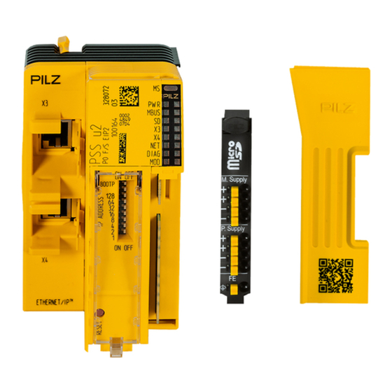
Page 8: Front View
DIP switch for setting the IP address and for activating BOOTP Reset pushbutton EtherNet/IP interface X3 and X4: RJ45 socket Product name Serial number Scope of supply Head module PSS u2 P0 F/S EIP2 with: – 1 x Terminal block 9-pin Operating Manual PSS u2 P0 F/S EIP2 1005376-EN-01... -
Page 9: Safety
Safety Safety Intended use The module PSS u2 P0 F/S EIP2 may only be used in the PSS u2 system. The module is designed for use in safety-related applications with – CIP Safety via EtherNet/IP non-safety-related applications with – EtherNet/IP The module meets the requirements of EN IEC 61508 up to SIL CL 3. -
Page 10: Safety Regulations
In safety-related applications, please comply with the mission time T in the safety-related characteristic data. When decommissioning, please comply with local regulations regarding the disposal of electronic devices (e.g. Electrical and Electronic Equipment Act). Operating Manual PSS u2 P0 F/S EIP2 | 10 1005376-EN-01... -
Page 11: Security
Perform a risk assessment in accordance with VDI/VDE 2182 or IEC 62443-3-2 and plan the security measures with care. If necessary, seek advice from Pilz Customer Support. Implemented security measures The password is saved in an encrypted format. - Page 12 Company firewall Machine firewall Internet Company network Machine network Product Configuration computer Fig.: Example network topology Note the network data [ for risk analysis and the security measures. Operating Manual PSS u2 P0 F/S EIP2 | 12 1005376-EN-01...
-
Page 13: Function Description
The total power consumption of the sensors, actuators and test pulses supplied via the input/output modules must be ≤ the maximum output power. If the periphery supply is missing, the "PWR" LED flashes and a message is entered in the diagnostic list. Operating Manual PSS u2 P0 F/S EIP2 | 13 1005376-EN-01... -
Page 14: Integrated Protection Mechanisms
Operational entry in the error stack Impact after a restart: Inputs retain their current input values Substitute values are used for the outputs until the connection to the controller has been re-established. Operating Manual PSS u2 P0 F/S EIP2 | 14 1005376-EN-01... -
Page 15: Ethernet/Ip
All the project data is stored in the head module. 5.6.2 Setting the IP address The IP address can be set using: DIP switch PASconfig (see Online help for PASconfig) BOOTP Operating Manual PSS u2 P0 F/S EIP2 | 15 1005376-EN-01... -
Page 16: Projects
RSLogix from Version 30. Special features when using a control system from Schneider Electric SE: We recommend that you use the device description file (EDS) from Pilz. The EDS file is available on the Internet at www.pilz.de. Operating Manual PSS u2 P0 F/S EIP2... -
Page 17: Diagnostic Object (0X64)
3…7 Reserved The Diagnostic Object supports the following services: Service Code Class Instance Service Name Description Get_Attribute_Single Read the value of one attribute Get_Attribute_All Read the value of all attributes Operating Manual PSS u2 P0 F/S EIP2 | 17 1005376-EN-01... -
Page 18: St Process Image
Module n.u. n.u. n.u. n.u. O3 PSS u2 ES4DOD PSS u2 ES 8DOD PSS u2 ES 16DOD O15 O14 O13 O12 O11 O10 O9 Legende: O: Output n.u.: not used Operating Manual PSS u2 P0 F/S EIP2 | 18 1005376-EN-01... -
Page 19: Cip Safety
The sequence of the FS output data depends on the slot number (beginning with slot 1). The length of the FS output data depends on the number and the type of configured FS modules. Operating Manual PSS u2 P0 F/S EIP2 | 19 1005376-EN-01... -
Page 20: Restart Interlock
The user program must link this control variable logically to every safe output with AND. The user program must reset this control variable to valid by reintegration. Only then will the values of the safe inputs be valid again. Operating Manual PSS u2 P0 F/S EIP2 | 20 1005376-EN-01... -
Page 21: Cip Safety Requirements On The User
FS reaction time (max.) = 2 x FS cycle time + tProc = 8 ms + tProc tProc: Processing time of the input and output modules (see Technical details in the oper- ating manual for the respective modules). Operating Manual PSS u2 P0 F/S EIP2 | 21 1005376-EN-01... -
Page 22: Installation
Damage due to electrostatic discharge! Electrostatic discharge can damage components. Ensure against discharge before touching the product, e.g. by touching an earthed, conductive sur- face or by wearing an earthed armband. Operating Manual PSS u2 P0 F/S EIP2 | 22 1005376-EN-01... -
Page 23: Dimensions In Mm
Installation Dimensions in mm 49,7 60,4 64,1 110,1 62,7 Fig.: Dimensions in mm Operating Manual PSS u2 P0 F/S EIP2 | 23 1005376-EN-01... -
Page 24: Installing The Head Module
The mounting rail inter- lock must be in the open position, to the left. 2. Rotate the mounting rail interlock to the right to lock the head module on the mounting rail Operating Manual PSS u2 P0 F/S EIP2 | 24 1005376-EN-01... -
Page 25: Interfaces
(e.g. through shock, vibration). Such measures include, for example, fixed installation and strain relief (see graphic "Options for attaching the data cable to the head module"). Operating Manual PSS u2 P0 F/S EIP2 | 25 1005376-EN-01... - Page 26 Interfaces Fig.: Additional options for fastening the data cable on the head module and locking the connector using cable ties Remove the cable ties before pulling the plug. Operating Manual PSS u2 P0 F/S EIP2 | 26 1005376-EN-01...
-
Page 27: Wiring
Details of the minimum range for cable cross sections on connection terminals can be found under "Technical details [ 34]". Use copper wiring. The mounting rail must be earthed on both sides. Operating Manual PSS u2 P0 F/S EIP2 | 27 1005376-EN-01... -
Page 28: Connecting The Module
+24 V DC 0 V DC +24 V DC 0 V DC Earthing Infeed for Infeed for module supply periphery supply Fig.: Separate power supplies for module supply and periphery supply Operating Manual PSS u2 P0 F/S EIP2 | 28 1005376-EN-01... - Page 29 Infeed for periphery supply Earthing Fig.: Common power supply for module supply and periphery supply Use the following fuses: Module supply: max. 6 A characteristic B/C Periphery supply: max. 10 A characteristic B/C Operating Manual PSS u2 P0 F/S EIP2 | 29 1005376-EN-01...
-
Page 30: Operation
Display elements The head module contains a number of status LEDs, which provide information on the status of various system sections. MBUS DIAG Fig.: LEDs of the head module PSS u2 P0 F/S EIP2 9.1.1 Colour State Meaning - - -... -
Page 31: X3, X4
One or more I/O connections timed out Communication has failed Red/green Device has discovered a network access error and the connection has failed or the device is in self- test Operating Manual PSS u2 P0 F/S EIP2 | 31 1005376-EN-01... -
Page 32: Diag
Device is in Idle or Standby mode Repairable error Internal error Red/green Device is in self-test or the configuration is not complete Legend LED on LED flashes LED flashes briefly LED off Operating Manual PSS u2 P0 F/S EIP2 | 32 1005376-EN-01... -
Page 33: Maintenance And Repair
No maintenance work is required on a PSS u2 system. Please return faulty PSS u2 sys- tems and/or modules to Pilz. INFORMATION When replacing modules and PSS u2 systems, observe the information on assembly/disassembly in the PSS u2 installation guidelines. Operating Manual PSS u2 P0 F/S EIP2 | 33 1005376-EN-01... -
Page 34: Technical Details
Maximum number of I/O connections Certification ODVA Transmission rate 100 Mbit/s CIP Safety Cycle time (RPI) 10 … 3200 ms Maximum data length 248 Byte Maximum number of I/O connections Operating Manual PSS u2 P0 F/S EIP2 | 34 1005376-EN-01... - Page 35 Type of potential isolation Functional insulation Rated surge voltage 2500 V Potential isolation between Module supply and EtherNet/IP (TM) Type of potential isolation Functional insulation Rated surge voltage 1500 V Operating Manual PSS u2 P0 F/S EIP2 | 35 1005376-EN-01...
-
Page 36: Safety Characteristic Data
The safety-related characteristic data (PFH, PFD) are mean values. They have been calcu- lated at an average ambient component temperature of 40 °C and apply for the ambient temperature range stated in the technical details. Operating Manual PSS u2 P0 F/S EIP2 | 36 1005376-EN-01... -
Page 37: Network Data
Tool in- 18080 Communication with the configuration terface tool Ether- EtherNetIP GET service Net/IP Ether- EtherNetIP SET service Net/IP Ether- Log data Net/IP Ether- In/out Process data Net/IP Operating Manual PSS u2 P0 F/S EIP2 | 37 1005376-EN-01... -
Page 38: Order Reference
Labelling strips for electronic module 23.5 x 328913 (10 pcs.) 10.5 mm (10 x DIN A4 sheet) PSS u2 A LA E2 Labelling strips for electronic module 103 x 328914 (10 pcs.) 10.5 mm (10 x DIN A4 sheet) Operating Manual PSS u2 P0 F/S EIP2 | 38 1005376-EN-01... - Page 39 We are represented internationally. Please refer to our homepage www.pilz.com for further details or contact our headquarters. Headquarters: Pilz GmbH & Co. KG, Felix-Wankel-Straße 2, 73760 Ostfildern, Germany Telephone: +49 711 3409-0, Telefax: +49 711 3409-133, E-Mail: info@pilz.com, Internet: www.pilz.com...
Need help?
Do you have a question about the PSS u2 P0 F/S EIP2 and is the answer not in the manual?
Questions and answers