
Related Manuals for Pilz PSS u2 ES PSP


Summary of Contents for Pilz PSS u2 ES PSP
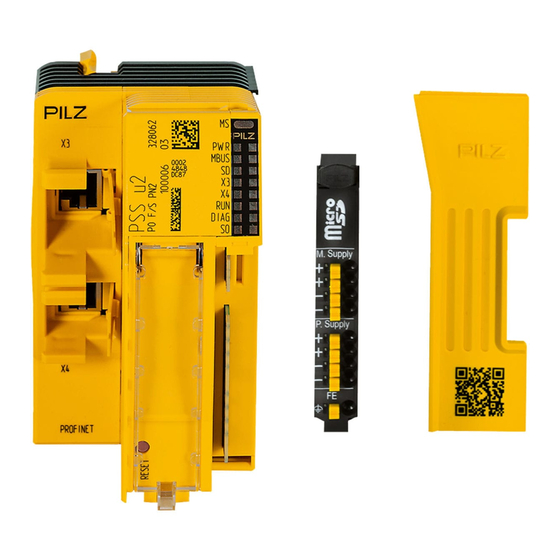
- Page 1 PSS u2 ES PSP Control system PSS u2 Remote I/O system PSS u2 Operating Manual-1003765-EN-03...
- Page 2 We do assure you that all persons are regarded without discrim- ination and on an equal basis. All rights to this documentation are reserved by Pilz GmbH & Co. KG. Copies may be made for the user's internal purposes. Suggestions and comments for improving this documenta- tion will be gratefully received.
-
Page 3: Table Of Contents
General wiring guidelines ......................7.1.1 Connection mechanism for terminal blocks ................Terminal configuration ......................Operation ..........................Display elements and messages ....................Technical details ........................Order reference ........................10.1 Product ............................. 10.2 Accessories ..........................Operating Manual PSS u2 ES PSP 1003765-EN-03... -
Page 4: Introduction
This operating manual explains the function and operation, describes the installation and provides guidelines on how to connect the product. This documentation is valid for the product PSS u2 ES PSP hardware version 01 or higher. It is valid until new documentation is published. -
Page 5: Overview
Details of the terminal blocks that can be used are available under "Intended Use". Module features Application of the product PSS u2 ES PSP: Electronic module to supply the PSS u2 system with periphery supply. The product has the following features:... -
Page 6: Safety
The module is supported by PASconfig from version 1.0.0 – We recommend that you always use the latest version (download from www.pilz.com). The module PSS u2 ES PSP may be used in conjunction with the following terminal block: 8-pin terminal block Safety regulations 3.2.1... -
Page 7: Warranty And Liability
In safety-related applications, please comply with the mission time T in the safety-related characteristic data. When decommissioning, please comply with local regulations regarding the disposal of electronic devices (e.g. Electrical and Electronic Equipment Act). Operating Manual PSS u2 ES PSP 1003765-EN-03... -
Page 8: Function Description
Periphery Supply Supply +24 V DC 24 V Fig.: Block diagram PSS u2 ES PSP Supply The module is supplied with voltage via the head module. The module refreshes the periphery supply for adjacent modules on the right. 4.2.1 Current load capacity Ensure you comply with the current load capacity of the periphery supply (see "Technical... -
Page 9: Address Assignment
Periphery supply switched on Not connected No overcurrent Overcurrent detected No external supply on the backplane External supply detected on the backplane Periphery supply is outside the voltage tolerance Periphery supply is within the voltage tolerance Operating Manual PSS u2 ES PSP 1003765-EN-03... -
Page 10: Installation
6.1.1 Dimensions The dimensions include the backplane, electronic module and terminal block. 12,5 51,1 111,1 Fig.: Dimensions in mm, including backplane, electronic module and terminal block Operating Manual PSS u2 ES PSP | 10 1003765-EN-03... -
Page 11: Inserting And Removing An Electronic Module
The mechanics of the electronic modules are designed for 20 plug in/out cycles. 6.2.1 Inserting an electronic module 1. Insert the electronic module into the suspen- sion lug on the back- plane. Operating Manual PSS u2 ES PSP | 11 1003765-EN-03... - Page 12 3. Insert the terminal block into the suspen- sion lug on the module. 4. Swivel the terminal block upwards until you hear it click into place. Operating Manual PSS u2 ES PSP | 12 1003765-EN-03...
-
Page 13: Removing An Electronic Module
2. Press the unlocking mechanism that is shown by the arrow and pull off the electronic module upwards. Operating Manual PSS u2 ES PSP | 13 1003765-EN-03... -
Page 14: Changing An Electronic Module During Operation
– Restart of the head module. After a restart, the system behaves as after a warm reset using a reset pushbutton (see operating manual of the head module, chapter “Reset pusbutton", section "Carrying out a warm reset (restart)"). Operating Manual PSS u2 ES PSP | 14 1003765-EN-03... -
Page 15: Wiring
Use a flat head screwdriver. Strip the wire back 9 mm. Feed the stripped cable as far as it will go into the opening for the spring-loaded terminal. Check that the cable is firmly seated. Operating Manual PSS u2 ES PSP | 15 1003765-EN-03... -
Page 16: Terminal Configuration
P0 (FE) P0 (FE) P0 / FE Connect to the 0 V supply and earth at a single point The module's supply voltage must be protected with an 8 A fuse. Operating Manual PSS u2 ES PSP | 16 1003765-EN-03... -
Page 17: Operation
See module's dia- voltage/overload) gnostic log Overtemperature(1) Internal errors See module's dia- gnostic log Legend LED on LED flashes LED flashes briefly LED off ) There are two levels of overtemperature. Operating Manual PSS u2 ES PSP | 17 1003765-EN-03... - Page 18 After the "too hot" message has been received, if the temperature drops back below the "too warm" threshold value, the module will switch to an error-free state. Messages about a missing periphery supply can be suppressed through the configura- tion. Operating Manual PSS u2 ES PSP | 18 1003765-EN-03...
-
Page 19: Technical Details
Vibration In accordance with the standard EN 60068-2-6 Frequency 8,4 - 150 Hz Acceleration 10 m/s² Shock stress In accordance with the standard EN 60068-2-27 Acceleration 150 m/s² Duration 11 ms Operating Manual PSS u2 ES PSP | 19 1003765-EN-03... - Page 20 2500 V Mechanical data Material Housing Mounting type plug-in Dimensions Height 110,8 mm Width 12,5 mm Depth 77 mm Weight 32 g Where standards are undated, the 2015-04 latest editions shall apply. Operating Manual PSS u2 ES PSP | 20 1003765-EN-03...
-
Page 21: Order Reference
61 x 11.5 mm, scope of supply: 10 pieces Coding elements Product type Features Order no. PSS u2 A CE E Coding elements for electronic modules, 328860 (10 pcs.) scope of supply: 10 pieces Operating Manual PSS u2 ES PSP | 21 1003765-EN-03... - Page 22 Order reference Backplanes Product type Features Order no. PSS u2 B 1 Backplane, 1 slot 328811 PSS u2 B 4 Backplane, 4 slots 328810 Operating Manual PSS u2 ES PSP | 22 1003765-EN-03...
- Page 23 We are represented internationally. Please refer to our homepage www.pilz.com for further details or contact our headquarters. Headquarters: Pilz GmbH & Co. KG, Felix-Wankel-Straße 2, 73760 Ostfildern, Germany Telephone: +49 711 3409-0, Telefax: +49 711 3409-133, E-Mail: info@pilz.com, Internet: www.pilz.com...
Need help?
Do you have a question about the PSS u2 ES PSP and is the answer not in the manual?
Questions and answers