
Related Manuals for Pilz PNOZ m EF 4AI


Summary of Contents for Pilz PNOZ m EF 4AI
- Page 1 PNOZ m EF 4AI Configurable, safe small controllers PNOZmulti 2 Operating Manual-1004650-EN-02...
- Page 2 Preface This document is the original document. All rights to this documentation are reserved by Pilz GmbH & Co. KG. Copies may be made for the user's internal purposes. Suggestions and comments for improving this documenta- tion will be gratefully received.
-
Page 3: Table Of Contents
..........................General installation guidelines....................Dimensions in mm ........................Connecting the base unit and expansion modules ..............Commissioning ........................Wiring............................Connection..........................Download modified project to the PNOZmulti system .............. Operation ..........................LED indicators .......................... Operating Manual PNOZ m EF 4AI 1004650-EN-02... - Page 4 Contents Technical details ........................Safety characteristic data ......................Order reference ........................Product ............................. Accessories ..........................Operating Manual PNOZ m EF 4AI 1004650-EN-02...
-
Page 5: Introduction
Introduction Introduction Validity of documentation This documentation is valid for the product PNOZ m EF 4AI from Version HW:01, FW:01.00. This operating manual explains the function and operation, describes the installation and provides guidelines on how to connect the product. - Page 6 Introduction INFORMATION This gives advice on applications and provides information on special fea- tures. Operating Manual PNOZ m EF 4AI 1004650-EN-02...
-
Page 7: Overview
Expansion module PNOZ m EF 4AI Jumper Unit features Application of the product PNOZ m EF 4AI: Analogue input module for connection to a base unit from the PNOZmulti 2 system The product has the following features: 4 analogue inputs for current measurement Each input can be configured separately Current range: 0 ... -
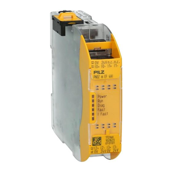
Page 8: Front View
Supply connections 0 V, 24 V to supply the sensors Supply connections 0 V, 24 V, 0 V, 24 V to supply the analogue input module and to supply the sensors LEDs Power, Run, Diag, Fault, I Fault, Operating Manual PNOZ m EF 4AI 1004650-EN-02... -
Page 9: Safety
Example: Protected inside space or control cabinet with protection type IP54 and corres- ponding air conditioning. The product PNOZ m EF 4AI can be used in furnaces in accordance with EN 298. You must make sure that there is sufficient overvoltage protection. -
Page 10: System Requirements
Operating Manual PNOZ m EF 4AI | 10 1004650-EN-02... -
Page 11: Warranty And Liability
Do not open the housing or make any unauthorised modifications. Please make sure you shut down the supply voltage when performing maintenance work (e.g. exchanging contactors). Operating Manual PNOZ m EF 4AI | 11 1004650-EN-02... -
Page 12: Function Description
EN IEC 62061: SIL CL 2. Two inputs have to be configured and checked for plausibility (see Plausibility check [ 17]). Sensor Channel 1 SIL 2 Threshold Plausibility Scaling Channel 2 Sensor value SIL 2 Operating Manual PNOZ m EF 4AI | 12 1004650-EN-02... -
Page 13: Measures For Achieving Process Safety
1 % + 0.5 % + 0.5 % = 2 %. The overall accuracy refers to the overall measuring range of 0 ... 25 mA Overall accuracy in mA in relation to the overall measuring range: 25 mA * 2 % = 0.5 mA Operating Manual PNOZ m EF 4AI | 13 1004650-EN-02... - Page 14 Sensor's measuring range: 0 ... 500 mbar at 4 ... 20 mA. Resolution of the sensor: 500 mbar / (20 – 4 mA) = 31.25 mbar per mA. The overall accuracy in mbar is therefore: 1 mA * 31.25 mbar per mA = 31.25 mbar. Operating Manual PNOZ m EF 4AI | 14 1004650-EN-02...
-
Page 15: Analogue Inputs
It must be ensured that open circuits and sensor errors are detected. If you do not use working range monitoring, other suitable measures must be taken. Lower failure information range (0 mA… R1) Default: 0 … 3.6 mA (e.g. circuit interrupted) Operating Manual PNOZ m EF 4AI | 15 1004650-EN-02... - Page 16 The numerical value is invalid, when R1 is undershot. The numerical value is valid again when R2 is exceeded. Example: Numerical value undershoots the working range Failure information Hysteresis Workspace Hysteresis Failure information Numerical value valid Operating Manual PNOZ m EF 4AI | 16 1004650-EN-02...
-
Page 17: Plausibility Check
When configuring a high tolerance time and simultaneously a small toler- ance period, the result may be a tolerance of approximately 100 %. Select the tolerance value as small as possible. Operating Manual PNOZ m EF 4AI | 17 1004650-EN-02... - Page 18 Tolerance period (t2) Minimum time that may elapse from one limit value overshoot to the next Deviation tolerance Leading signal Plausibility signal Analogue value valid Fig.: Leading signal remains within the tolerance limits Operating Manual PNOZ m EF 4AI | 18 1004650-EN-02...
- Page 19 Analogue value valid Fig.: Leading signal exceeds the tolerance time (t1) Deviation tolerance Leading signal Plausibility signal Analogue value valid Fig.: Leading signal does not maintain the duration of the tolerance period (t2) Operating Manual PNOZ m EF 4AI | 19 1004650-EN-02...
-
Page 20: Scaling
You can define switching thresholds, which can be used to monitor certain process vari- ables (e.g. temperature values). You can monitor whether a numerical value is greater or less than a configured switching threshold. Operating Manual PNOZ m EF 4AI | 20 1004650-EN-02... -
Page 21: Range Monitoring
2 threshold values are configured per switching threshold. One threshold value (switch-on threshold) defines when the affected output is switched on. The second threshold value (switch-off threshold) defines when the output will be switched off again. Operating Manual PNOZ m EF 4AI | 21 1004650-EN-02... -
Page 22: Diagnostics
The fieldbus address is configured in the element Diagnostics. Then the Diagnostics ele- ment is connected to the required numerical output of an element. Fig.: Input i0 is assigned to the Data ID 1 Operating Manual PNOZ m EF 4AI | 22 1004650-EN-02... -
Page 23: Block Diagram
I0+ I0- I1+ I1- I2+ I2- I3+ I3- 24 V Supply Input I Input I Input I Input I Input 24 V DC 0-25 mA 0-25 mA 0-25 mA 0- 25mA Supply Data (FS) Operating Manual PNOZ m EF 4AI | 23 1004650-EN-02... -
Page 24: Installation
Connect the base unit and the expansion modules as described in the operating manuals for the base modules. The terminator must be fitted to the last expansion module Install the expansion module in the position configured in the PNOZmulti Configurator. Operating Manual PNOZ m EF 4AI | 24 1004650-EN-02... - Page 25 Please refer to the document "PNOZmulti System Expansion" for details of the number of modules that can be connected to the base unit and the module types. Operating Manual PNOZ m EF 4AI | 25 1004650-EN-02...
-
Page 26: Commissioning
The 6 supply connections 24 V and 0 V to the terminal blocks X3 and X4 are interconnec- ted internally. – The supply of the analogue input module PNOZ m EF 4AI has to be made via the supply connections 24 V and 0 V at the terminal block X4. - Page 27 Supply connections 24 V and 0 V are used to supply the analogue input module and to supply the sensors. The terminals I0- … I3- and 0 V must be bridged. PNOZ m EF 4AI Sensor (SIL2) Sensor (SIL2) Sensor (SIL2) Sensor (SIL2) Operating Manual PNOZ m EF 4AI | 27 1004650-EN-02...
- Page 28 24 V 4-wire connection, supply voltage of sensors via analogue input module Supply connections 24 V and 0 V are used to supply the analogue input module and to supply the sensors. Operating Manual PNOZ m EF 4AI | 28 1004650-EN-02...
- Page 29 Commissioning PNOZ m EF 4AI Sensor (SIL2) Sensor (SIL2) Sensor (SIL2) Sensor (SIL2) Operating Manual PNOZ m EF 4AI | 29 1004650-EN-02...
- Page 30 The 0 V- connections of the external power supplies can be interconnected. 0V/24V- Sensor PNOZ m EF 4AI Sensor (SIL2) 0V/24V- Sensor Sensor (SIL2) 0V/24V- Sensor Sensor (SIL2) 0V/24V- Sensor Sensor (SIL2) 24 V 0V/24V- Sensor Operating Manual PNOZ m EF 4AI | 30 1004650-EN-02...
-
Page 31: Download Modified Project To The Pnozmulti System
Proceed as described in the operating manual for the base unit. NOTICE For the commissioning and after every user program change, you must check whether the safety devices are functioning correctly. Operating Manual PNOZ m EF 4AI | 31 1004650-EN-02... -
Page 32: Operation
Diag Fault IFault No supply voltage Analogue input module PNOZ m EF 4AI is in the start-up phase. Analogue input module PNOZ m EF 4AI is running without error. Analogue input module PNOZ m EF 4AI is in stop condition. - Page 33 Green The measured current at the relevant analogue input is inside the working range. The measured current at the relevant analogue input is outside the working range. The analogue input is not configured. Operating Manual PNOZ m EF 4AI | 33 1004650-EN-02...
-
Page 34: Technical Details
16 Bit (15 Bit + sign) 0,78 µA Value of least significant bit (LSB) Input resistance 156 Ohm + approx. 1.6 V threshold voltage Max. continuous current 30 mA 10 kHz Scan rate Safety-related accuracy (1 input) Operating Manual PNOZ m EF 4AI | 34 1004650-EN-02... - Page 35 EN 60529 In accordance with the standard Housing IP20 Terminals IP20 Mounting area (e.g. control cabinet) IP54 Potential isolation Potential isolation between Sensor and system voltage Functional insulation Type of potential isolation Operating Manual PNOZ m EF 4AI | 35 1004650-EN-02...
- Page 36 Stripping length with spring-loaded terminals 9 mm Dimensions Height 101,4 mm Width 22,5 mm Depth 120 mm Weight 108 g Where standards are undated, the 2018-07 latest editions shall apply. Operating Manual PNOZ m EF 4AI | 36 1004650-EN-02...
-
Page 37: Safety Characteristic Data
A safety function's SIL/PL values are not identical to the SIL/PL values of the units that are used and may be different. We recommend that you use the PAScal software tool to calculate the safety function's SIL/PL values. Operating Manual PNOZ m EF 4AI | 37 1004650-EN-02... -
Page 38: Order Reference
751 004 Set screw terminals 1 set of screw terminals 750 004 Terminator, jumper Product type Features Order no. PNOZ mm0.xp connector Jumper yellow/black to connect the modules, 10 pieces 779 260 left Operating Manual PNOZ m EF 4AI | 38 1004650-EN-02... - Page 39 We are represented internationally. Please refer to our homepage www.pilz.com for further details or contact our headquarters. Headquarters: Pilz GmbH & Co. KG, Felix-Wankel-Straße 2, 73760 Ostfildern, Germany Telephone: +49 711 3409-0, Telefax: +49 711 3409-133, E-Mail: info@pilz.com, Internet: www.pilz.com...
Need help?
Do you have a question about the PNOZ m EF 4AI and is the answer not in the manual?
Questions and answers