Still RX70-40 Original Instructions Manual
Lpg truck
Hide thumbs
Also See for RX70-40:
- Original instructions manual (392 pages) ,
- Quick reference manual (10 pages) ,
- Original instructions manual (388 pages)

Related Manuals for Still RX70-40


Summary of Contents for Still RX70-40
- Page 1 Original instructions LPG truck RX70-40 RX70-45 RX70-50 7335 7336 7337 7338 57348011850 EN - 08/2020 - 12...
- Page 3 Internet address and QR code The information can be accessed at any time by pasting the address https://m.still.de/vdma in a web browser or by scanning the QR code. 57348011850 EN - 08/2020 - 12...
-
Page 5: Table Of Contents
Table of contents Foreword Your truck ............General . - Page 6 Table of contents Damage, defects and misuse of safety systems ....... Length of the fork arms .
- Page 7 Table of contents Operation Checks and tasks before daily use ........Visual inspections .
- Page 8 Table of contents Blue-Q efficiency mode ..........Functional description .
- Page 9 STILL SafetyLight (variant) ........
- Page 10 Table of contents FleetManager (variant) ..........Shock recognition (variant) .
- Page 11 Table of contents Transporting the truck ..........Transport .
- Page 12 Table of contents Preserving operational readiness ........De-icing the evaporator .
-
Page 13: Foreword
Foreword... -
Page 14: Your Truck
Foreword Your truck Your truck General The truck described in these operating instruc- tions corresponds to the applicable standards and safety regulations. If the truck is to be operated on public roads, it must conform to the existing national regula- tions for the country in which it is being used. -
Page 15: Ce Labelling
Foreword Your truck CE labelling The manufacturer uses CE labelling to indi- cate that the truck complies with the standards and regulations valid at the time of marketing. This is confirmed by the issued EC declaration of conformity. The CE labelling is attached to the nameplate. -
Page 16: Ec Declaration Of Conformity In Accordance With Machinery Directive
Foreword Your truck EC declaration of conformity in accordance with Machinery Directive Declaration STILL GmbH Berzeliusstraße 10 D-22113 Hamburg Germany We declare that the Industrial truck according to these operating instructions Model according to these operating instructions conforms to the latest version of the Machinery Directive 2006/42/EC. -
Page 17: Labelling Points Overview
Foreword Your truck Labelling points overview Decal information: Fixing point for lifting gear Decal information: Caution / Read the oper- Manufacturer's label text ating instructions / Fasten seat belt / Apply Warning sign: Danger due to shearing/ parking brake when leaving the truck / Pas- Danger due to high fluid pressure sengers are not allowed / Do not jump off if Warning sign: Do not stand underneath the... -
Page 18: Nameplate
Foreword Your truck Nameplate The truck can be identified from the informa- tion on the nameplate. The information for the battery weights (5, 6) and the ballast weight (7) only applies to elec- Type-Modèle-Typ / Serial no.-No. de série-Serien-Nr. / year-année-Baujahr tric forklift trucks. -
Page 19: Stvzo (Road Traffic Licensing Regulations) Information
Foreword Your truck StVZO (Road Traffic Licensing Reg- ulations) information This label includes information on the weight and load distribution of the truck. 7094_003-098 Tare weight (in kg) Permitted total weight (in kg) Permitted front axle weight (in kg) Permitted rear axle weight (in kg) Payload (in kg) 57348011850 EN - 08/2020 - 12... -
Page 20: Using The Truck
Foreword Using the truck Using the truck Proper usage The truck described in these operating instruc- tions is suitable for lifting, transporting and stacking loads. The truck may only be used for its proper pur- pose as set out and described in these operat- ing instructions. -
Page 21: Place Of Use
Foreword Using the truck DANGER There is a risk of fatal injury from falling off the truck while it is moving! – It is prohibited to carry passengers on the truck. The truck may not be operated in areas where there is a risk of fire, explosion or corrosion, or in areas that are particularly dusty. -
Page 22: Using Working Platforms
Foreword Using the truck NOTE Please observe the definition of the following responsible person: "operating company". DANGER Risk of fatal poisoning! It is dangerous to leave the engine running in en- closed spaces. The engine consumes oxygen and emits carbon dioxide, carbon monoxide and other poisonous gases. -
Page 23: Information About The Documentation
Foreword Information about the documentation Information about the documentation Documentation scope Original operating instructions ● Original operating instructions for attach- ● ments (variant) Spare parts list ● Depending on the truck equipment, "UPA" ● operating instructions may also be provided NOTE Refer to the additional information in the sec- tion entitled "Rules for the operating company... -
Page 24: Supplementary Documentation
Foreword Information about the documentation The operating company must ensure that all users have received, read and understood these operating instructions. Safely store the complete documentation and pass on to the subsequent operating company when transferring or selling the truck. NOTE Please observe the definition of the following responsible persons: "operating company"... -
Page 25: Issue Date And Topicality Of The Operating Instructions
The issue date of these operating instructions can be found on the title page. STILL is constantly engaged in the further de- velopment of trucks. These operating instruc- tions are subject to change, and any claims based on the information and/or illustrations contained in them cannot be asserted. -
Page 26: List Of Abbreviations
Foreword Information about the documentation List of abbreviations NOTE This list of abbreviations applies to all types of operating instructions. Not all of the abbrevia- tions that are listed here will necessarily ap- pear in these operating instructions. Abbrevi- Meaning Explanation ation Display operating unit... - Page 27 Foreword Information about the documentation Abbrevi- Meaning Explanation ation Uncertainty of measurement of sound pressure levels Light Emitting Diode Light emitting diode Sound pressure level at the workplace Average continuous sound pressure level in the driver's compartment Distance of the centre of gravity of the Load centre of gravity load from the front face of the fork backs Maximum permissible air concentrations...
-
Page 28: Definition Of Directions
Foreword Information about the documentation Definition of directions The directions "forwards" (1), "backwards" (3), "right" (2) and "left" (4) refer to the installation position of the parts as seen from the driver's compartment; the load is to the front. 6210_001-031 Schematic views View of functions and operations... - Page 29 Foreword Information about the documentation View of the display operating unit NOTE Views of operating statuses and values in the display of the display operating unit are exam- ples and partly dependent on the truck equip- ment. As a result, the displays shown of the actual operating statuses and values can vary.
-
Page 30: Environmental Considerations
Foreword Environmental considerations Environmental considerations Packaging During delivery of the truck, certain parts are packaged to provide protection during trans- port. This packaging must be removed com- pletely prior to initial start-up. ENVIRONMENT NOTE The packaging material must be disposed of properly after delivery of the truck. -
Page 31: Safety
Safety... -
Page 32: Definition Of Terms Used For Responsible Persons
Safety Definition of terms used for responsible persons Definition of terms used for responsible persons Operating company The operating company is the natural or legal person or group who operates the truck or on whose authority the truck is used. The operating company must ensure that the truck is only used for its proper purpose and in compliance with the safety regulations set out... -
Page 33: Drivers
Safety Definition of terms used for responsible persons Drivers This truck may only be driven by suitable per- sons who are at least 18 years of age, have been trained in driving, have demonstrated their skills in driving and handling loads to the operating company or an authorised represen- tative, and have been specifically instructed to drive the truck. - Page 34 Safety Definition of terms used for responsible persons Prohibition of use by unauthorised per- sons The driver is responsible for the truck during working hours. He must not allow unauthor- ised persons to operate the truck. When leaving the truck, the driver must secure it against unauthorised use, e.g.
-
Page 35: Basic Principles For Safe Operation
Safety Basic principles for safe operation Basic principles for safe operation Insurance cover on company prem- ises In many cases, company premises are restric- ted public traffic areas. NOTE The business liability insurance should be re- viewed to ensure that, in the event of any damage caused in restricted public traffic areas, there is insurance cover for the truck in respect of third parties. - Page 36 Risk of injury if the truck tips over! Even if an approved restraint system is in use, there is still a residual risk that the driver could be injured if the truck tips over. The risk of injury can be re- duced by using the restraint system in conjunction with the seat belt.
-
Page 37: Changes To The Overhead Guard And Roof Loads
Safety Basic principles for safe operation Decal information with the following data must be permanently affixed to the truck so that it is clearly visible: Type of modification ● Date of modification ● Name and address of the company that car- ●... -
Page 38: Warning Regarding Non-Original Parts
STILL. CAUTION Installation and/or use of such products may there- fore have a negative impact on the design features of the truck and thus impair active and/or passive driv- ing safety. -
Page 39: Length Of The Fork Arms
Safety Basic principles for safe operation Length of the fork arms DANGER Risk of accident due to the incorrect selection of fork arms! – The fork arms must match the depth of the load. If the fork arms are too short, the load may fall off the arms after it has been picked up. -
Page 40: Medical Equipment
Safety Basic principles for safe operation Only use wheels and tyres approved by the ● manufacturer Only use high-quality products ● Wheels and tyres approved by the manufac- turer can be found on the spare parts list. If other wheels or tyres are to be used, authori- sation from the manufacturer must be ob- tained beforehand. -
Page 41: Exercise Caution When Handling Gas Springs And Accumulators
Safety Basic principles for safe operation Exercise caution when handling gas springs and accumulators WARNING Gas springs are under high pressure. Improper re- moval results in an elevated risk of injury. For ease of operation, various functions on the truck can be supported by gas springs. - Page 42 Safety Basic principles for safe operation – For help with selecting the correct fork arms, contact the authorised service centre. 57348011850 EN - 08/2020 - 12...
-
Page 43: Residual Risk
Safety Residual risk Residual risk Residual dangers, residual risks Despite careful working and compliance with standards and regulations, the occurrence of other risks when using the truck cannot be en- tirely excluded. The truck and all other system components comply with current safety requirements. Nev- ertheless, even when the truck is used for its proper purpose and all instructions are fol- lowed, some residual risk cannot be excluded. -
Page 44: Special Risks Associated With Using The Truck And Attachments
Safety Residual risk with these regulations either intentionally or carelessly. Stability The stability of the truck has been tested to the latest technological standards and is guar- anteed provided that the truck is used properly and according to its intended purpose. These standards only take into account the dynamic and static tipping forces that can arise during specified use in accordance with the operating... - Page 45 Safety Residual risk the truck correctly and without the risk of acci- dents. 57348011850 EN - 08/2020 - 12...
-
Page 46: Overview Of Hazards And Countermeasures
Safety Residual risk Overview of hazards and countermeasures NOTE This table is intended to help evaluate the hazards in your facility and applies to all drive types. It does not claim to be complete. – Observe the national regulations for the country in which the truck is being used. - Page 47 Safety Residual risk Hazard Course of action Check note Notes √ done - Not applicable Impermissible usage Provide operating in- German Ordinance on (improper usage) structions Industrial Safety and Health (BetrSichV) and German Health and la- bour protection law (ArbSchG) Written notice of in- German Ordinance on struction to driver...
-
Page 48: Danger To Employees
Safety Residual risk Hazard Course of action Check note Notes √ done - Not applicable When operating driverless transport systems Roadway quality inad- Clean/clear roadways German Ordinance on equate Industrial Safety and Health (BetrSichV) Loading equipment in- Reposition load on pal- German Ordinance on correct/slipped Industrial Safety and... - Page 49 Safety Residual risk included in the hazard assessment. Attach- ments possess their own CE labelling and likewise are not included for that reason. The operating company must, however, select the type and equipment of the trucks so as to comply with the local provisions for deploy- ment.
-
Page 50: Safety Tests
Safety Safety tests Safety tests Regular safety inspection of the truck Safety inspection based on time and ex- traordinary incidents The operating company must ensure that the truck is checked by a specialist at least once a year or after particular incidents. As part of this inspection, a complete check of the technical condition of the truck must be performed with regard to accident safety. -
Page 51: Regularly Checking The Level Of Harmful Substances In The Exhaust Gas
Safety Safety tests association regulations BGV D34 entitled "Ac- cident prevention regulation for the use of LPG". NOTE Please observe the definition of the following responsible persons: "operating company" and "competent person". The LPG system must be checked: Recurring in regular intervals, but at least ●... -
Page 52: Insulation Testing
Safety Safety tests Observe the national regulations in the rele- vant country! In Germany, perform checks in accordance with § 37 of the employers' liability insurance association regulations BGV D34 entitled "Accident prevention regulation for the use of LPG". The type and scope of tests may differ accord- ing to the country. -
Page 53: Safety Regulations For Handling Consumables
Safety Safety regulations for handling consumables Safety regulations for handling consumables Permissible consumables WARNING Consumables can be dangerous! – Observe the safety regulations for handling these materials; refer to the section entitled "Safety reg- ulations for handling consumables". – Note the safety datasheets provided by the manu- facturer of the consumables in question. -
Page 54: Oils
Safety Safety regulations for handling consumables Oils DANGER Oils are flammable! – Follow the statutory regulations. – Do not allow oils to come into contact with hot engine parts. – No smoking, fires or naked flames! DANGER Oils are toxic! –... -
Page 55: Hydraulic Fluid
Safety Safety regulations for handling consumables ENVIRONMENT NOTE Oil is a water-polluting substance! Always store oil in containers that comply ● with the applicable regulations. Avoid spilling oils. ● Spilt oil should be removed immediately ● with oil-binding agents and disposed of ac- cording to the regulations. -
Page 56: Battery Acid
Safety Safety regulations for handling consumables ENVIRONMENT NOTE Hydraulic fluid is a water-polluting substance. Always store hydraulic fluid in containers ● that comply with regulations Avoid spills ● Spilt hydraulic fluid should be removed im- ● mediately with oil-binding agents and dis- posed of according to the regulations Dispose of old hydraulic fluid according to ●... -
Page 57: Lpg
Safety Safety regulations for handling consumables Always observe the "Use of LPG" (BGV D34) accident prevention regulations published by the main trade association of employers' liabil- ity insurance carriers, as well as the relevant national guidelines. Liquid gases are the combustible gases, PRO- PANE, BUTANE and their mixtures. - Page 58 Safety Safety regulations for handling consumables DANGER Risk of poisoning! Please ensure that trucks with LPG sys- tems are only operated in rooms that are entirely or partially enclosed if there is no possibility that hazardous concentrations of noxious exhaust gas components ex- ist in the air.
- Page 59 Safety Safety regulations for handling consumables Storing pressurised-gas vessels The cylinder and main shut-off valves must be closed as soon as the truck is parked. The special regulations governing the storage of pressurised-gas containers must be ob- served without fail, in addition to country-spe- cific regulations where appropriate.
-
Page 60: Coolant And Cooling Fluid
Safety Safety regulations for handling consumables Coolant and cooling fluid WARNING Coolant and cooling fluid can be hazard- ous to your health and the environment! Coolants are chemical corrosion inhibi- tors and cooling system protecting agents such as Glysantin. The cooling fluid is an appropriate mixture of water and coolant. - Page 61 Safety Safety regulations for handling consumables – Always observe national regulations con- cerning the disposal of used oil. 57348011850 EN - 08/2020 - 12...
-
Page 62: Emissions
Safety Emissions Emissions The values specified apply to a standard truck uring vibration" and DIN EN 12096 "Mechani- (see technical datasheet). Different tyres, lift cal vibration - Declaration and verification of masts, additional units etc. may produce dif- vibration emission values". ferent values. - Page 63 Safety Emissions Heat hydrocarbons (CH), aldehydes, nitrogen oxide ) and soot. The components CO, CH, DANGER and soot are poisonous or are health hazards, and should not be inhaled at high Risk of burns caused by hot exhaust concentrations. gases! Exhaust gases or components that carry exhaust gases (e.g.
- Page 64 Safety Emissions 57348011850 EN - 08/2020 - 12...
-
Page 65: Overviews
Overviews... -
Page 66: Truck Overview
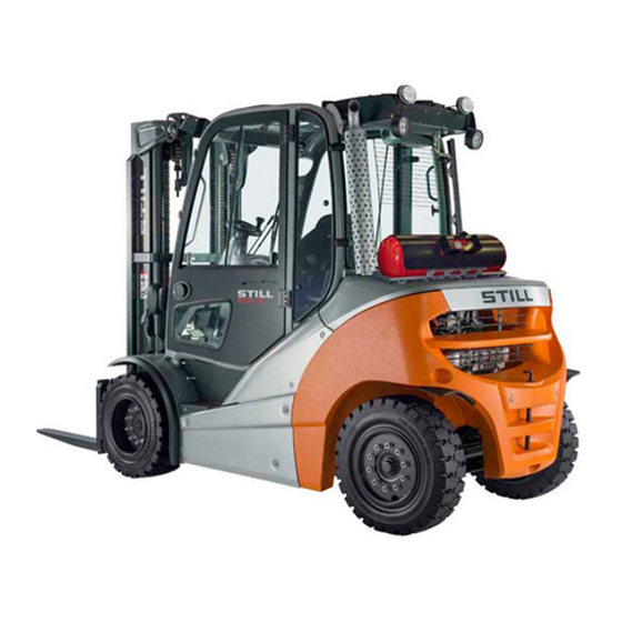
Overviews Truck overview Truck overview 7335_003-001 Lift mast Steering axle Overhead guard Bonnet Driver's compartment Drive axle LPG tank Fork arms Towing device Fork carriage 57348011850 EN - 08/2020 - 12... -
Page 67: Overview Of Driver's Compartment
Overviews Overview of driver's compartment Overview of driver's compartment Parking brake lever Bottle holder for max. 1.5 l bottles Steering wheel Driver's seat Key switch Compartment Display and operating unit Filler cap for windscreen washer reservoir Compartment for the operating instructions Accelerator pedal Operating devices for hydraulic and drive Brake pedal... -
Page 68: Operating Devices And Display Elements
Overviews Operating devices and display elements Operating devices and display elements Display operating unit Hazard warning system button Operating hours display Front windscreen wiper button Time display (digital) Working spotlight button Particle filter warning display Drive programme selector button Rotating beacon display Lighting button Interior lighting display Lighting symbol... - Page 69 Overviews Operating devices and display elements The truck can be equipped with the following operating devices: Double mini-lever ● Triple mini-lever ● Quadruple mini-lever ● Joystick 4Plus ● Fingertip switch ● Mini-console ● 57348011850 EN - 08/2020 - 12...
-
Page 70: Double Mini-Lever
Overviews Operating devices and display elements Double mini-lever "Lift mast" 360° lever Function key "5th function" Function key "F1" "Attachments" cross lever Function key "F2" Signal horn button "Drive direction/turn indicator" cross lever For alterations, contact the authorised serv- ● NOTE ice centre. -
Page 71: Three-Way Mini-Lever
Overviews Operating devices and display elements Three-way mini-lever 7325_003-026 "Lift mast" 360° lever Function key "5th function" Function key "F1" "Auxiliary hydraulics 1" operating lever Function key "F2" "Auxiliary hydraulics 2" operating lever "Drive direction/turn indicator" cross lever Signal horn button For alterations, contact the authorised serv- ●... -
Page 72: Four-Way Mini-Lever
Overviews Operating devices and display elements Four-way mini-lever 7325_003-027 "Lift/lower" operating lever Function key "5th function" "Tilt" operating lever "Auxiliary hydraulics 1" operating lever Function key "F1" "Auxiliary hydraulics 2" operating lever Function key "F2" Signal horn button "Drive direction/turn indicator" cross lever For alterations, contact the authorised serv- ●... -
Page 73: Joystick 4Plus
Overviews Operating devices and display elements Joystick 4Plus 6210_003-087 Horizontal rocker button for "3rd hydraulic LED for clamp locking mechanism (variant) function", tilt the lift mast Slider for the "4th hydraulic function", e.g. Pictograms for the basic hydraulic functions reach frame forwards/backwards Pictograms for the 5th hydraulic function and Vertical rocker button for the "drive direction"... -
Page 74: Fingertip
Overviews Operating devices and display elements Fingertip 7325_003-028 Function key "F1" "Attachments" operating lever Function key "F2" "Attachments" operating lever Left turn indicator button "Tilt" operating lever Signal horn button "Lift/lower" operating lever Right turn indicator button Drive direction switch Function key "5th function"... -
Page 75: Mini Console
Overviews Operating devices and display elements Mini console The mini console is located on the steering column below the steering wheel. 7311_003-056 Travel direction switch Direction indicator switch 57348011850 EN - 08/2020 - 12... - Page 76 Overviews Operating devices and display elements 57348011850 EN - 08/2020 - 12...
-
Page 77: Operation
Operation... -
Page 78: Checks And Tasks Before Daily Use
Operation Checks and tasks before daily use Checks and tasks before daily use Visual inspections WARNING Risk of injury from falling off the truck! When climbing onto the truck, there is a risk of getting stuck or slipping and fall- ing. - Page 79 Operation Checks and tasks before daily use Component Course of action Check the area under the forklift truck for leaking Underside consumables. Perform a visual inspection for integrity. Overhead guard, guard grille (variant) Check for secure mounting. Steps Make sure they are clean (free of ice, not slippery). Perform a visual inspection for integrity.
-
Page 80: Checking The Side Cover Is Locked
Operation Checks and tasks before daily use Component Course of action Perform a visual inspection for wear and damage. Make sure that only rims of the same type from the same manufacturer are fitted. Wheels, tyres In the event of uneven tyre wear, replace both tyres. -
Page 81: Climbing Into And Out Of The Truck
Operation Checks and tasks before daily use Climbing into and out of the truck WARNING Risk of injury when climbing into and out of the truck due to slipping, striking parts of the truck or becom- ing stuck! If the footwell cover is very dirty or smeared with oil, there is a risk of slipping. -
Page 82: Climbing Into And Out Of A Truck With A Raised Driver's Cab
Operation Checks and tasks before daily use To assist with climbing into and out of the truck, the footwell must be used as a step (5) and the handle (1) must be used for support. The post of the overhead guard (2) can also be used for support. - Page 83 Operation Checks and tasks before daily use CAUTION Components may become damaged through incor- rect use! Truck components, such as the driver's seat, steer- ing wheel, parking brake lever etc., are not designed to be used for climbing in and out of the truck and may be damaged due to misuse.
-
Page 84: Shelves And Cup Holders
Operation Checks and tasks before daily use – Grip the handle (4) with your right hand and do not let go. – Place your right foot on the bottom step (5). – Place your left foot on the ground and climb down from the truck. - Page 85 Operation Checks and tasks before daily use WARNING On some equipment variants, the amount of head clearance on the truck may be restricted. On these specific equipment variants, the distance between the head and the lower edge of the roofing sheet must be at least 40 mm.
- Page 86 Operation Checks and tasks before daily use Adjusting the seat backrest Do not put pressure on the seat backrest while engaging it. – Lift and hold the lever (2) – Push the seat backrest into the desired po- sition. –...
- Page 87 Operation Checks and tasks before daily use NOTE The driver's weight has been selected correct- ly when the arrow (4) is in the centre of the in- spection window. If the seat does not move any further when you pump the weight adjust- ing lever, the minimum or maximum weight setting has been reached.
-
Page 88: Adjusting The Armrest
Operation Checks and tasks before daily use Switching the seat heater (variant) on and off NOTE The seat heater only functions if the seat con- tact switch is active, i.e. when the driver is sit- ting on the driver's seat. –... -
Page 89: Adjusting The Steering Column
Operation Checks and tasks before daily use Adjusting the length of the armrest – Release the star-grip handle (1) by turning it anti-clockwise. – Shift the armrest (2) into the desired posi- tion. – Tighten the star-grip handle by turning it clockwise. -
Page 90: Unlocking The Emergency Off Switch
Operation Checks and tasks before daily use Unlocking the emergency off switch NOTE Only trucks with a joystick 4Plus (variant) have an emergency off switch. – Pull out the emergency off switch (1) until it unlatches. 6321_003-142 Switching on the key switch WARNING Before switching on the key switch, all tests prior to commissioning must be performed without any de-... - Page 91 Operation Checks and tasks before daily use – Insert the switch key (1) into the key switch and turn to position "I". 7090_001-002 This initiates a self-test. All lamps in the drive direction and turn indicator displays light up briefly.
- Page 92 Operation Checks and tasks before daily use When the key switch is switched on, the dis- play shows the welcome screen in the set lan- guage until the truck controllers have fully started up. Standard display elements Fuel level If there is sufficient amount of gas availa- ble, the indicator is not visible in the dis- play field.
-
Page 93: Access Authorisation With Pin Code (Variant)
Operation Checks and tasks before daily use Access authorisation with PIN code (variant) Description Trucks equipped with the "Access authorisa- tion with PIN code" variant are protected against unauthorised use by a five-digit driver PIN. Up to fifty different driver PINs can be de- fined so that the same truck can be used by different drivers, each with their own driver PIN. - Page 94 PIN is only known to per- sons with corresponding access authorisation. The driver PINs are stored in the truck control unit. These are still available if the display and operating unit has been changed. The author- ised service centre can use a diagnostic de- vice to read out the driver PIN and, if necessa- ry, restore the factory default driver PIN.
- Page 95 Operation Checks and tasks before daily use After three invalid entry attempts, the mes- sage appears. The input is CODE DENIED then locked for five minutes before another at- tempt can be made. BQ_024_en_V2 Defining the driver PIN NOTE The driver PINs can be defined only by per- sons with the appropriate access authorisa-...
- Page 96 Operation Checks and tasks before daily use appears in the display. PASSWORD – Enter the four-digit password (factory de- fault: 2777) using the buttons (1). – Confirm the input using Softkey (2). BQ_030_en_V2 appears in the display. CONFIGURATION –...
- Page 97 Operation Checks and tasks before daily use Selecting the driver PIN In the menu, there are fifty ACCESS CODE possible driver PINs to choose from. The digit sequences can be set or changed in submenu. NEW CODE Once the menu has been ac- ACCESS CODE cessed, the...
- Page 98 Operation Checks and tasks before daily use appears in the display. CONFIRM submenu is used to confirm CONFIRM the new driver PIN. – Enter the new driver PIN for a second time in the field (8) using the buttons CONFIRM or Softkeys (7).
- Page 99 Operation Checks and tasks before daily use After three incorrect entries, the CODE DE- message appears. NIED The display switches back to the ACCESS menu. The desired driver PIN must be CODE re-defined. BQ_024_en_V2 Changing the password It is recommended that you change the factory default password.
- Page 100 Operation Checks and tasks before daily use appears in the display. PASSWORD – Enter the current password using the but- tons (1). – Confirm the input using Softkey (2). BQ_030_en_V2 appears in the display. CONFIGURATION – Use the drive program selection button (1) and the menu change button (3) to select menu.
- Page 101 Operation Checks and tasks before daily use appears in PASSWORD/PASSWORD LEVEL the display. – Use the drive program selection button (1) and the menu change button (4) to select the desired (2). PASSWORD LEVEL – Confirm your selection using Soft- (3).
-
Page 102: Operating The Signal Horn
Operation Checks and tasks before daily use – To exit the configuration menu, press Soft- (2) repeatedly until the standard display appears. Operating the signal horn – Push the signal horn button (1). The signal horn sounds. NOTE The signal horn is used to warn people against imminent danger or to announce your intention to overtake. - Page 103 Operation Checks and tasks before daily use DANGER Only bracket doors (variant) or the driver's cab (var- iant) with closed, fixed doors constitute a driver re- straint system. Plastic doors (weather protection) do not constitute a restraint system! If you need to open or remove the doors, you must use an alternative suitable restraint system (e.g.
- Page 104 Operation Checks and tasks before daily use Fastening on a steep slope The automatic blocking mechanism prevents the belt from being extended whenever the truck is on a steep gradient. It is not possible to pull the seat belt any further out of the belt retractor.
-
Page 105: Using The Driver's Cab
Operation Checks and tasks before daily use CAUTION The seat belt may be damaged by heat! Do not subject the buckle or belt retractor to exces- sive heat when thawing. – Do not use air warmer than 60°C when thawing. Using the driver's cab ... - Page 106 Operation Checks and tasks before daily use DANGER Risk of explosion from spark discharge! – Do not use a striking tool when open- ing and closing. WARNING LPG can cause frostbite on the skin. – Wear protective gloves. CAUTION Opening the cylinder valve too quickly can lead to the system icing over.
-
Page 107: Opening The Lpg Cylinder Valve For A Double-Cylinder Holder
Operation Checks and tasks before daily use Opening the LPG cylinder valve for a double-cylinder holder DANGER There is a risk of explosion if LPG es- capes. Escaping LPG may explode when ex- posed to ignition sources and cause se- rious accidents. - Page 108 Operation Checks and tasks before daily use – To open the upper gas cylinder (1), push the lever (2) down. – Open the cylinder valve (3) of the upper gas cylinder by slowly turning the star-grip han- dle anti-clockwise. –...
-
Page 109: Opening The Lpg Tank Shut-Off Valve
Do not start the engine if a leak or smell of gas or other such indications are evi- dent. Do not start the engine. – Contact your STILL service centre. – Check if the hose (1) is securely connected to the LPG tank. - Page 110 Checks and tasks before daily use If a leak is detected: Do not start the engine. ● Close the shut-off valve (2). ● Contact your supervisor and/or STILL serv- ● ice centre. The fuel level display (3) (variant) displays how much LPG is available.
-
Page 111: Starting The Engine
Operation Checks and tasks before daily use Starting the engine DANGER Risk to health from exhaust gases! It is dangerous to leave the engine running in en- closed spaces. The engine consumes oxygen and emits carbon dioxide, carbon monoxide and other poisonous gases. -
Page 112: Checking The Brake System For Correct Function
Operation Checks and tasks before daily use Checking the brake system for cor- rect function DANGER If the brake system fails, the truck is insufficiently braked or not braked at all, so there is a risk of ac- cident! –... -
Page 113: Checking The Steering System For Correct Function
Operation Checks and tasks before daily use Checking the steering system for correct function DANGER If the hydraulics fail, there is a risk of accident as the steering characteristics have changed. – Do not operate the truck if it has a defective steer- ing system. -
Page 114: Zero Adjustment Of The Load Measurement (Variant)
Operation Checks and tasks before daily use NOTE In trucks with an electric parking brake, the electric parking brake will be applied as soon as the truck comes to a stop. – Pull out the emergency off switch (1). The knob is unlocked and pops out. The truck performs an internal self-test and is then ready for operation again. -
Page 115: Checking The Vertical Lift Mast Position (Variant) For Correct Function
Operation Checks and tasks before daily use – Press the Softkey (1). The zero adjustment of the load measurement is switched on. The symbol is displayed. The message appears on the LOWER FORKS display. NOTE During the following process, the fork carriage must be lowered slightly and then stopped abruptly. -
Page 116: Filling The Washer System
Operation Checks and tasks before daily use – Release the operating device to tilt and ac- tuate again. The lift mast must tilt forwards fully and move gently as far as the end stop. Filling the washer system CAUTION Components may become damaged due to the ef- fects of frost! Water expands when it freezes. -
Page 117: Cleaning The Dust Valve
Operation Checks and tasks before daily use Cleaning the dust valve – Open the service flap on the right-hand side under the driver's cab; see C hapter ⇒ "Opening the side service flap", Page 320 . – Press the dust valve (1) on the air filter housing between your fingers until no more dust is emitted. -
Page 118: Operating The Display-Operating Unit
Operation Operating the display-operating unit Operating the display-operating unit Displays Standard display elements In the factory setting, the following indicators can be seen in the display and operating unit: Fuel level Shows the fuel level in the fuel tank in %. Drive programme Displays the current drive programme nu- merically (1-5). -
Page 119: Adjusting The Displays
Operation Operating the display-operating unit Adjusting the displays NOTE The parking brake must always be engaged when you adjust the displays. The displays cannot be adjusted if the parking brake is not engaged. NOTE When adjusting the displays, do not actuate the hydraulic system operating devices. -
Page 120: Symbols In The Display
Operation Operating the display-operating unit The display changes to the menu. PASSWORD NOTE It may be necessary to enter a password in or- der to configure the displays. This depends on the configuration of the display-operating unit. For configuration of the display-operating ●... - Page 121 Operation Operating the display-operating unit Description Symbol Service required Lift limitation Reference cycle Battery charging Drive program Hour meter Odometer Daily hour meter Daily odometer Speed Steering angle Load Time Hydraulic system Exh.gas purifier Coolant temperature Fuel level Blue-Q Power rating (average) Power rating (trend) Symbols for warning messages Description...
- Page 122 Operation Operating the display-operating unit Description Symbol Malfunction in the electrical system General malfunction Symbols for softkey functions of auxili- ary equipment The following symbols for softkey functions are used on the left of the display for auxiliary equipment: Description Symbol Empty field No display...
- Page 123 Operation Operating the display-operating unit Symbols for softkey functions for menu navigation and for acknowledging mes- sages The following symbols for the softkey func- tions are used on the left of the display for menu navigation and to acknowledge messag- Description Symbol Empty field...
- Page 124 Operation Operating the display-operating unit Screen for entering the fleet manager pass- word: BQ_037 Screen for entering the driver PIN (access code): BQ_038 57348011850 EN - 08/2020 - 12...
-
Page 125: Setting The Date Or Time
Operation Operating the display-operating unit Setting the date or time – Switch to the menu; see CONFIGURATION the chapter entitled "Adjusting the displays". – Press the Drive programme button (1) or the Menu change button (2) repeatedly until option appears. TIME –... -
Page 126: Setting The Language
Operation Operating the display-operating unit NOTE The daily operating hours are reset in the same manner. Setting the language 1 2 3 4 The displays can be shown in additional lan- guages: – Switch to the menu; see CONFIGURATION the chapter entitled "Adjusting the displays". -
Page 127: Configuring Blue-Q Efficiency Mode
Operation Operating the display-operating unit Changing the Softkey functions: A grey bar (3) highlights the Softkey column. This is the right-hand column in the example shown here. These additional functions can now be switched on and off via the corre- sponding Softkeys (2). -
Page 128: Shock Recognition (Variant)
Operation Operating the display-operating unit FIXED-FLEX Blue-Q is turned on whenever the truck is ● commissioned. The driver can use the Blue- Q button to switch efficiency mode on and off at any time while the truck is being oper- ated –... -
Page 129: Blue-Q Efficiency Mode
Operation Blue-Q efficiency mode Blue-Q efficiency mode Functional description The Blue-Q efficiency mode affects both the drive unit and the activation of the additional consumers, and reduces the truck's energy consumption. If the efficiency mode has been activated, the acceleration behaviour of the truck changes to make acceleration more moderate. -
Page 130: Switching Off Additional Consumers
Operation Blue-Q efficiency mode Switching off additional consumers If the Blue-Q efficiency mode is activated, the controller switches off various additional con- sumers after a few seconds in certain condi- tions. The additional consumers available de- pend on the truck equipment. The following ta- ble shows the conditions that cause additional consumers to be switched off. -
Page 131: Switching Efficiency Mode Blue-Q On And Off
Operation Blue-Q efficiency mode Switching efficiency mode Blue-Q on and off NOTE The Blue-Q efficiency mode can be switched on and off in the STANDARD and FIXED- FLEX operating modes. If the FIXED operat- ing mode is configured in the display-operat- ing unit, the Blue-Q button is disabled and the Blue-Q efficiency mode is switched on perma- nently. -
Page 132: Driving
Operation Driving Driving Safety regulations when driving Driving conduct The driver must follow the public rules of the road when driving in company traffic. The speed must be appropriate to the local conditions. For example, the driver must drive slowly around corners, in tight passageways, when driving through swing-doors, at blind spots, or on uneven surfaces. - Page 133 There is a risk of acci- dent! – Do not use devices during travel or when handling loads. – Set the volume so that warning signals can still be heard. WARNING In areas where use of mobile phones is prohibited, use of a mobile phone or radio telephone is not per- mitted.
-
Page 134: Roadways
For pallets, these are 7321_003-019 as follows: with pallet with pallet Aisle width (mm) 1000 x 1200 800 x 1200 crosswise lengthwise RX70-40 3912 4112 RX70-45 3942 4142 RX70-50 4037 4237 The truck may only be used on roadways that... - Page 135 The gradient values in no way represent the normal daily operating conditions. Max. gradient in % with load without load RX70-40 RX70-45 RX70-50 The ascending and descending gradients must not exceed the gradients listed above and must have a rough surface.
-
Page 136: Setting The Drive Programmes
Operation Driving fixed elements of the surrounding area. The height is based on the overall height of the lift mast and the dimensions of the load. Observe the technical data (see C hapter "Technical ⇒ data", Page 351 ). Rules for roadways and the working area It is only permitted to drive on routes author- ised for traffic by the operating company (see... -
Page 137: Actuating The Vertical Rocker Switch For The "Drive Direction", Joystick 4Plus Version
Operation Driving Drive program Speed (km/h) Acceleration (%) (forwards/backwards) Deceleration (%) (forwards/backwards) Reversing (%) (forwards/backwards) Brake retardation (%) (electric brake booster) Actuating the vertical rocker switch for the "drive direction", joy- stick 4Plus version – For the "forwards" drive direction, push the vertical rocker button for the "drive direc- tion"(1) upwards (A). -
Page 138: Actuating The Drive Direction Switch, Fingertip Version
Operation Driving Actuating the drive direction switch, fingertip version – For the "forwards" drive direction, push the drive direction switch (1) forwards – For the "backwards" drive direction, push the drive direction switch backwards 7325_003-031 Actuating the vertical rocker switch ... -
Page 139: Actuating The Drive Direction Switch, Mini-Console Version
Operation Driving Actuating the drive direction switch, mini-console version – For the "forwards" drive direction, push the drive direction switch (1) forwards. – For the "backwards" drive direction, push the drive direction switch to the rear. NOTE Alternatively, the drive direction can also be selected using the drive direction switches on the operating devices. - Page 140 Operation Driving The indicator for the selected drive direction ("forwards" (1) or "backwards" (2)) lights up on the display and operating unit. NOTE Depending on the equipment, an acoustic sig- nal (variant) may sound a warning during re- verse travel, the warning light (variant) may light up or the hazard warning system (variant) may flash.
-
Page 141: Starting Drive Mode, Dual Pedal Version (Variant)
If the truck still cannot be operat- ed, park the truck securely and contact your authorised service centre. - Page 142 Operation Driving – Actuate the right-hand accelerator pedal (1) to drive "forward" and actuate the left-hand accelerator pedal (2) to drive "backward". NOTE In the dual pedal version, the drive direction switches on the operating devices do not func- tion.
- Page 143 If the truck still cannot be operat- ed, park the truck securely and contact your authorised service centre.
-
Page 144: Operating The Service Brake
Operation Driving Operating the service brake The electric brake converts the acceleration energy of the truck into electrical energy. This causes the truck to decelerate. In addition, the truck can be braked using the service brake: – Press the brake pedal (2). In the first section of the brake pedal's travel, only the regenerative braking takes effect. -
Page 145: Actuating The Mechanical Parking Brake
Operation Driving Zero braking (variant) DANGER Risk of accident! Trucks with zero braking (variant) are not braked when the accelerator pedal is released. – Bring the truck to a standstill by actuating the brake pedal. If your truck features the zero braking equip- ment variant, the electric brake function is dis- abled. - Page 146 Operation Driving Apply the parking brake – Pull the parking brake lever (1) down fully and release. The parking brake lever swivels back half the distance into the middle position automatically. The parking brake is engaged and the wheels are blocked.
-
Page 147: Steering
Operation Driving Steering DANGER If the hydraulics fail, there is a risk of accident as the steering characteristics have changed. – Do not operate the truck if it has a defective steer- ing system. – Steer the truck by turning the steering wheel (1) accordingly. -
Page 148: Driving On Ascending And Descending Gradients
Operation Driving Driving on ascending and descend- ing gradients DANGER Danger to life! Driving on ascending and descending gradients car- ries special dangers! – Always follow the instructions below. – On ascending and descending gradients, the load must be carried facing uphill. –... - Page 149 Operation Driving Driving on ascending and descend- ing gradients DANGER Danger to life! Driving on ascending and descending gradients car- ries special dangers! – Always follow the instructions below. – On ascending and descending gradients, the load must be carried facing uphill. –...
-
Page 150: Reducing Speed With A Raised Load (Variant)
Operation Driving Reducing speed with a raised load (variant) This function (variant) reduces the speed of the truck with a raised load. 7321_003-052_en_V2 Automatic shut-off of the internal combustion engine (variant) The truck is equipped with an automatic shut- off function that shuts off the internal combus- tion engine when certain conditions apply si- multaneously after a preset waiting time has... - Page 151 Operation Driving NOTE The waiting time is set to 120 seconds at the factory, but can be changed at a later date. Contact the authorised service centre. ● 57348011850 EN - 08/2020 - 12...
-
Page 152: Parking
Operation Parking Parking Parking the truck securely and switching it off DANGER There is a risk of being run over if the truck rolls away and therefore a danger to life. – The truck should not be parked on a slope. - Page 153 60 seconds and the error message "LPG AUTO. VALVE" appears on the display and operating unit. The truck can still be operated but your authorised serv- ice centre must be notified of the error imme- diately. The error message is shown on the...
-
Page 154: Wheel Chock (Variant)
Operation Parking – For trucks with LPG cylinders, close the cyl- inder valve (7). 7314_003-016 Wheel chock (variant) The wheel chock (variant) is used to prevent the truck from rolling away on a slope. – Lift handle (2) on the support mounting. –... -
Page 155: Lifting
Operation Lifting Lifting Lifting system variants The movement of the fork carriage and the lift mast heavily depends on the following equip- ment: The lift mast with which the truck is equip- ● ped, see C hapter "Types of lift mast", ⇒ ... -
Page 156: Lift Mast Vertical Position (Variant)
Operation Lifting Overriding and reactivating the auto- matic lift cut out If a load needs to be lifted to the truck's maxi- mum lift height and the automatic lift cut out function is not required, it is possible to over- ride the lift cut out. - Page 157 Operation Lifting CAUTION Risk of damage to property due to the lift mast collid- ing with racks or other objects! – Before using the "lift mast vertical position" com- fort feature, position the truck at a sufficient dis- tance from racks and other objects. The "lift mast vertical position"...
- Page 158 Operation Lifting Display of the "lift mast vertical position" The driver can see the mast tilt on the display and operating unit screen. The bar in the dis- play shows the current mast tilt relative to the "lift mast vertical position". The arrow above the bar marks the vertical position of the lift mast.
- Page 159 Operation Lifting Tilting the lift mast forwards with the "lift mast vertical position" – Press Softkey (1). The "automatic mast vertical positioning" com- fort feature is switched on. The (2) symbol is displayed. – Tilt the lift mast forwards. NOTE The way in which the lifting system is operated depends on the operating devices included in...
-
Page 160: Types Of Lift Mast
Operation Lifting Possible restrictions on the "lift mast vertical position" In some circumstances, the lift mast cannot move exactly into the preset vertical position. Possible causes include: Uneven ground ● Bent fork ● Bent attachment ● Worn tyres ● Severely deformed lift mast ●... -
Page 161: Malfunctions During Lifting Mode
Operation Lifting Telescopic mast During lifting, the lift mast rises over the outer lift cylinders, bringing the fork carriage with it via the chains (fork carriage rises twice as fast as the inner lift mast). The top edge (1) of the inner lift mast can therefore be higher than the fork carriage. - Page 162 Operation Lifting An incorrect extension sequence may, for in- stance, result from: The hydraulic oil temperature being too low. ● The fork carriage becoming blocked in the ● inner lift mast. Blocking of the free lift cylinder. ● The chain roller becoming blocked at the ●...
-
Page 163: Hydraulic Blocking Function
Operation Lifting Hydraulic blocking function The hydraulic blocking function ensures that all hydraulic functions are disabled whenever the seat switch in the driver's seat is unloa- ded. This is when the driver stands up from the driver's seat or exits the truck. All hydraulic functions are disabled in this case: Lifting the load ●... - Page 164 Operation Lifting DANGER Reaching into or climbing between moving parts of the truck (e.g. lift mast, sideshifts, working equip- ment, load carrying devices etc.) can lead to seri- ous injury or death and is therefore prohibited. – Observe the safety regulations for handling loads. –...
-
Page 165: Controlling The Lifting System Using A Double Mini-Lever
Operation Lifting Controlling the lifting system using a double mini-lever DANGER Reaching into or climbing between moving parts of the truck (e.g. lift mast, sideshifts, working equip- ment, load carrying devices etc.) can lead to seri- ous injury or death and is therefore prohibited. –... -
Page 166: Controlling The Lifting System Using A Triple Mini-Lever
Operation Lifting Controlling the lifting system using a triple mini-lever DANGER Reaching into or climbing between moving parts of the truck (e.g. lift mast, sideshifts, working equip- ment, load carrying devices etc.) can lead to seri- ous injury or death and is therefore prohibited. –... -
Page 167: Controlling The Lifting System Using A Quadruple Mini-Lever
Operation Lifting Controlling the lifting system using a quadruple mini-lever DANGER Reaching into or climbing between moving parts of the truck (e.g. lift mast, sideshifts, working equip- ment, load carrying devices etc.) can lead to seri- ous injury or death and is therefore prohibited. –... -
Page 168: Controlling The Lifting System Using The Joystick 4Plus
Operation Lifting Controlling the lifting system using the joystick 4Plus DANGER Reaching into or climbing between moving parts of the truck (e.g. lift mast, sideshifts, working equip- ment, load carrying devices etc.) can lead to serious injury or death and is therefore prohibited. –... - Page 169 Operation Lifting Tilting the lift mast To tilt the lift mast forwards: – Tilt the horizontal rocker button (2) to the left (C). To tilt the lift mast backwards: – Tilt the horizontal rocker button (2) to the right (D). 6210_003-090 7312_003-022_V2 57348011850 EN - 08/2020 - 12...
- Page 170 Operation Lifting Fork-carriage sideshift To move the fork carriage to the left. – Push the joystick 4Plus (1) to the left (E). To move the fork carriage to the right: – Push the joystick 4Plus (1) to the right (F). NOTE The symbols on the joystick 4Plus indicate the direction of movement of the lift mast or the...
-
Page 171: Controlling The Lifting System Using The Fingertip
Operation Lifting Controlling the lifting system using the fingertip DANGER Reaching into or climbing between moving parts of the truck (e.g. lift mast, sideshifts, working equip- ment, load carrying devices etc.) can lead to seri- ous injury or death and is therefore prohibited. –... -
Page 172: Changing The Fork Arms
Operation Lifting The lift cylinders have in-built fixed stops to prevent the fork arms from hitting the ground. The lower stop makes inserting the forks into a pallet more comfortable. The driver cannot adjust the fork wear protec- tion manually. However, the fork wear protec- tion must be continually adjusted as the wear on the front tyres increases. - Page 173 Operation Lifting Removal – Select a pallet corresponding to the fork arm size. – Set down the pallet next to the fork carriage on the side chosen for removal. – Lift the fork carriage until the fork arms are approx.
-
Page 174: Fork Extension (Variant)
Operation Lifting NOTE If the truck is equipped with the "load meas- urement" comfort feature, a "zero adjustment of the load measurement" must always be performed after the fork arms have been changed. Otherwise, correct load measurement cannot be guaranteed. Fork extension (variant) DANGER There is a risk of being run over if the truck rolls... - Page 175 Operation Lifting Attachment DANGER Risk to life from falling load! At least 60% of the length of the fork extension must lie on the fork arm. A maximum 40% overhang over the fork arm end is permissible. The fork extension must also be secured against slipping from the fork arm.
-
Page 176: Operation With Reversible Fork Arms (Variant)
Operation Lifting Operation with reversible fork arms (variant) DANGER Risk to life from falling load! Standard fork arms are not structurally designed for reverse operation. If this instruction is not observed, it can lead to material failure and the load falling. –... - Page 177 Operation Lifting Reversible fork arms (1) can be used to reach an additional lift height. The reversible fork arms are installed on the fork carriage in the same manner as standard fork arms. Loads may be lifted on and beneath the reversible fork arms.
-
Page 178: Handling Loads
Operation Handling loads Handling loads Safety regulations when handing loads The safety regulations for handling loads are shown in the following sections. DANGER There is a risk to life caused by falling loads or if parts of the truck are being lowered. –... -
Page 179: Before Taking Up Load
Operation Handling loads Before taking up load Load capacity The load capacity indicated for the truck on the capacity rating plate may not be excee- ded. The load capacity is influenced by the load centre of gravity and the lift height as well as by the tyres, if applicable. -
Page 180: Load Measurement (Variant)
Operation Handling loads Example Weight of load to be lifted: 880 kg (3) Load distance from fork back: 500 mm (1) Permitted lift height: 5230 mm (2) WARNING Risk of accident from the truck losing stability! The permissible load of the attachments (variant) 5230 and the reduced lifting capacity of the combination of truck and attachment must not be exceeded. - Page 181 Operation Handling loads The load measurement has an accuracy of +/-3% of the rated capacity of the truck. NOTE In order to ensure accuracy at all times, a zero adjustment of the load measurement must be carried out. Zero adjustment is required. as part of daily commissioning ●...
- Page 182 Operation Handling loads NOTE The method of operating the lifting system de- pends on the operating devices included in the truck's equipment. – Ensure that the truck has been in operation for a period of time before carrying out the load measurement.
-
Page 183: Picking Up Loads
Operation Handling loads When load measurement has been performed correctly, the determined load weight (3) is shown on the display. NOTE If the load measurement is invalid, the value "-9999 kg" is displayed in the operating unit. 6210_003-073_en Picking up loads To make sure that the load is securely suppor- ted, it must be ensured that the fork arms are sufficiently far apart and are positioned as far... -
Page 184: Danger Area
Operation Handling loads Adjusting the fork – Lift the locking lever (1) and move the fork arms to the desired position. – Allow the locking lever to snap back into place. The load centre of gravity must be midway be- tween the fork arms. -
Page 185: Transporting Pallets
Operation Handling loads DANGER Danger of death from falling loads! – Never walk or stand underneath sus- pended loads. Transporting pallets As a rule, loads (e.g. pallets) must be trans- ported individually. Transporting multiple loads at the same time is only permitted: when instructed by the supervisor and ●... -
Page 186: Load Pick Up
Operation Handling loads DANGER Loss of stability. Slipping or swinging suspended loads can lead to a loss of stability and cause the truck to tip over. – When transporting suspended loads, observe the following instructions Instructions for transporting suspended loads: Swinging loads must be prevented by using ●... - Page 187 Operation Handling loads – Only store pallets which do not exceed the specified maximum size. Damaged loading equipment and incorrectly formed loads must not be stored. – Attach or secure the load to the load-carry- ing equipment so that the load cannot move or fall.
- Page 188 Operation Handling loads – Insert the fork as far under the load as pos- sible. Stop the truck as soon as the fork back is resting on the load. The centre of gravity of the load must be positioned be- tween the fork arms in the middle.
- Page 189 Operation Handling loads – Lower the load while maintaining ground clearance. 5060_003-102 – Tilt the lift mast backwards. The load can be transported. 5060_003-101 57348011850 EN - 08/2020 - 12...
-
Page 190: Transporting Loads
Operation Handling loads Transporting loads NOTE Observe the information in the chapter entitled "Safety regulations when driving". DANGER The higher a load is lifted, the less stable it be- comes. The truck can tip over or the load can fall, increasing the risk of accident! Driving with a raised load and the lift mast tilted for- ward is not permitted. -
Page 191: Setting Down Loads
Operation Handling loads – Never drive with a load protruding to the side (e.g. with the sideshift)! 6210_800-014 Setting down loads DANGER Risk of accident due to changed moment of tilt! The load centre of gravity and the moment of tilt move due to tilting the lift mast forwards with a raised load or due to the load slipping. - Page 192 Operation Handling loads – Drive up to the stack with the load lowered in accordance with regulations. – Set lift mast to vertical. – Lift the load to the stacking height. – Drive the truck towards the rack carefully. 6210_800-015 –...
-
Page 193: Driving On Lifts
Operation Handling loads Driving on lifts The driver may only use this truck on lifts with a sufficient rated capacity and for which the operating company has been granted authori- sation. DANGER There is a risk to life if you are crushed or run over by the truck. -
Page 194: Driving On Loading Bridges
Operation Handling loads Driving on loading bridges DANGER Risk of accident if the truck crashes! Steering movements can cause the tail end to veer off the loading bridge towards the edge. This may cause the truck to crash. The lorry driver and the truck driver must agree on the lorry's departure time. -
Page 195: Attachments
Fitting attachments If the truck is equipped with an integrated at- tachment (variant) at the factory, the specifica- tions in the STILL operating instructions for in- tegrated attachments must be observed. If attachments are fitted at the place of use,... - Page 196 Operation Attachments DANGER There is risk to life caused by a falling load! Attachments that hold the load by exerting pressure on it (e.g. clamps) must be controlled additionally by a second operating function (lock) that is actuated to prevent an unintentional release of the load. If such an attachment is retrofitted, a second operat- ing function for actuation must also be retrofitted.
-
Page 197: Releasing The Pressure From The Hydraulic System
Operation Attachments Load capacity with attachment The permissible load capacity of the attach- ment and the allowable load (load capacity and load moment) of the truck must not be ex- ceeded by the combination of attachment and payload. The specifications of the manufactur- er and supplier of the attachment must be complied with. - Page 198 Operation Attachments – Actuate the operating lever (1) for control- ling the hydraulic functions repeatedly in the direction of the arrow, as far as the end po- sition. The valves open and the hydraulic system is depressurised. – Switch off the key switch. 7312_003-184 57348011850 EN - 08/2020 - 12...
-
Page 199: General Instructions For Controlling Attachments
Operation Attachments General instructions for controlling attachments The way in which attachments (variant) are controlled depends on the operating devices included in the truck's equipment. Essentially, a distinction is drawn between: Double mini-lever ● Double mini-lever with a 5th function (var- ●... - Page 200 Operation Attachments NOTE All the attachments described fall into the cat- egory of equipment variants. Please see the respective operating instructions for an exact description of the respective movements/ actions of the attachment fitted. 57348011850 EN - 08/2020 - 12...
-
Page 201: Controlling Attachments Using A Double Mini-Lever
Operation Attachments Controlling attachments using a double mini-lever The attachments (variants) are controlled in this version using the "attachments" cross lev- er (1). The pictograms on the "attachments" cross lever show the respective functions that are activated by this lever. This essentially involves the following: –... - Page 202 Operation Attachments – Note the following attachment functions and pictograms. Move sideshift frame or fork forwards Move sideshift frame or fork back- wards Move sideshift to the left Move sideshift to the right Adjust fork arms: open Adjust fork arms: close Swivel lift mast or fork to the left Swivel lift mast or fork to the right Release load retainer...
-
Page 203: Controlling Attachments Using The Double Mini-Lever And The 5Th Function
Operation Attachments Controlling attachments using the double mini-lever and the 5th func- tion NOTE For technical reasons, clamping attachments must not be controlled via the 5th function. NOTE The "lift mast" 360° lever (3) and the "attach- ments" cross lever (2) control four hydraulic functions. - Page 204 Operation Attachments – Note the following attachment functions and pictograms. Move sideshift frame or fork forwards Move sideshift frame or fork back- wards Move sideshift to the left Move sideshift to the right Adjust fork arms: open Adjust fork arms: close Swivel lift mast or fork to the left Swivel lift mast or fork to the right Release load retainer...
-
Page 205: Controlling Attachments Using A Triple Mini-Lever
Operation Attachments Controlling attachments using a tri- ple mini-lever The attachments (variant) are controlled in this version using operating levers (1) and (2). The pictograms on the operating levers show the respective functions that are activated by these levers. This essentially involves the following: –... - Page 206 Operation Attachments – Note the following attachment functions and pictograms! Move sideshift frame or fork forwards Move sideshift frame or fork back- wards Move sideshift to the left Move sideshift to the right Adjust fork arms: open Adjust fork arms: close Swivel lift mast or fork to the left Swivel lift mast or fork to the right Release load retainer...
-
Page 207: Controlling Attachments Using The Triple Mini-Lever And The 5Th Function
Operation Attachments Controlling attachments using the triple mini-lever and the 5th function NOTE For technical reasons, clamping attachments cannot be controlled via the 5th function. NOTE The "lift mast" 360° lever (3) and operating levers (1) and (2) control four hydraulic func- tions. - Page 208 Operation Attachments – Note the following attachment functions and pictograms. Adjust fork arms: open Adjust fork arms: close Rotate to the left Rotate to the right 5060_003-122 57348011850 EN - 08/2020 - 12...
-
Page 209: Controlling Attachments Using A Quadruple Mini-Lever
Operation Attachments Controlling attachments using a quadruple mini-lever The attachments (variant) are controlled in this version using operating levers (1) and (2). The pictograms on the operating levers show the respective function that is activated by these levers. This essentially involves the following: –... - Page 210 Operation Attachments – Note the following attachment functions and pictograms! Move sideshift frame or fork forwards Move sideshift frame or fork back- wards Move sideshift to the left Move sideshift to the right Adjust fork arms: open Adjust fork arms: close Swivel lift mast or fork to the left Swivel lift mast or fork to the right Release load retainer...
-
Page 211: Controlling Attachments Using The Quadruple Mini-Lever And The 5Th Function
Operation Attachments Controlling attachments using the quadruple mini-lever and the 5th function NOTE For technical reasons, clamping attachments cannot be controlled via the 5th function. NOTE Operating levers (1) to (4) are used to control four hydraulic functions. The designation "5th function"... - Page 212 Operation Attachments – Note the following attachment functions and pictograms. Adjust fork arms: open Adjust fork arms: close Rotate to the left Rotate to the right 5060_003-122 57348011850 EN - 08/2020 - 12...
-
Page 213: Controlling Attachments Via The Joystick 4Plus
Operation Attachments Controlling attachments via the joy- stick 4Plus In this equipment, the attachments (variant) are controlled via the joystick 4Plus (1). The pictograms on the decal information about operation of the joystick 4Plus show the re- spective functions that are activated by the in- dividual operating devices of the joy- stick 4Plus. -
Page 214: Controlling Attachments Using The Joystick 4Plus And The 5Th Function
Operation Attachments Controlling attachments using the joystick 4Plus and the 5th function NOTE For technical reasons, clamping attachments cannot be controlled via the 5th function. NOTE The 5th hydraulic function can be used to con- trol an attachment. The pictograms on the joy- stick 4Plus show which attachment functions can be controlled using the 5th function. -
Page 215: Controlling The Attachments With The Fingertip
Operation Attachments Controlling the attachments with the fingertip The attachments (variant) are controlled in this version using the operating levers (1). The pictograms on the operating levers show the functions that are activated by that lever. – Move the operating lever (1) forwards The attachment moves in the direction of movement shown in the upper part of the pic- togram. -
Page 216: Controlling Attachments With The Fingertip And 5Th Function
Operation Attachments Controlling attachments with the fin- gertip and 5th function NOTE For technical reasons, clamping attachments cannot be controlled via the 5th function. NOTE The designation "5th function" refers to the fact that the four operating levers control four functions, while the "5th function"... - Page 217 Operation Attachments – Press function key (4) NOTE The arrow (5) under the function key indicates which operating lever is equipped with the "5th function". The "5th function" is switched to the 3rd oper- ating lever; see sticker (6). 7325_003-045 –...
-
Page 218: Clamp Locking Mechanism (Variant)
Operation Attachments – Note the following attachment functions and pictograms. Move side shift frame or fork for- wards/backwards Move sideshift to the left/right Adjust fork arms: open/close Swivel lift mast or fork to the left/right Release/clamp load retainer Push off/pull in load Turn to the left/right Tip shovel over/tip shovel back 6210_003-035... - Page 219 Operation Attachments Double mini-lever – To release the clamp locking mechanism, push the cross lever (1) forwards. The LED for button (2) lights up as long as the clamp locking mechanism is released. NOTE The hydraulic function for opening the clamp is available for one second after the clamp locking mechanism is released.
- Page 220 Operation Attachments Quadruple mini-lever – To release the clamp locking mechanism, push the operating lever (1) forwards. The LED for button (2) lights up as long as the clamp locking mechanism is released. NOTE The hydraulic function for opening the clamp is available for one second after the clamp locking mechanism is released.
-
Page 221: Taking Up A Load Using Attachments
Operation Attachments Fingertip switch – To release the clamp locking mechanism, push the operating lever (1) forwards. The LED for button (2) lights up as long as the clamp locking mechanism is released. NOTE The hydraulic function for opening the clamp is available for one second after the clamp locking mechanism is released. - Page 222 Operation Attachments Load capacity Q (kg) (1) ● Lift height h (mm) (2) ● Load distance C (mm) (3) ● 57348011850 EN - 08/2020 - 12...
-
Page 223: Auxiliary Equipment
Operation Auxiliary equipment Auxiliary equipment Switching the lighting on and off Driving lights – To switch on the parking light, press the button (1). The front sidelights and the rear lights light up. On the variant with StVZO (German Road Traffic Licensing Regulations) equipment, the licence plate lamp also lights up. -
Page 224: Switching The Working Spotlight For Reverse Travel On And Off
Operation Auxiliary equipment Switching the working spotlight for reverse travel on and off The working spotlight for reverse travel is at- tached to the overhead guard at the rear. It provides optimal illumination of the roadway if the truck is travelling in reverse. –... -
Page 225: Switching The Hazard Warning System On And Off
Operation Auxiliary equipment Switching the hazard warning sys- tem on and off – To switch on the hazard warning system, press the button (1). All turn indicators and indicator lights (2) flash. – To switch off the hazard warning system, press the button (1) again. - Page 226 Operation Auxiliary equipment The turn indicators and the corresponding turn indicator displays (2) or (3) flash. – Switch off the turn indicators by moving the cross lever to the centre position. 5060_003-012_V2 Fingertip version – Switch on the turn indicators by actuation the corresponding left-hand or right-hand turn indicator button (1).
- Page 227 Operation Auxiliary equipment The turn indicators and the corresponding turn indicator displays (2) or (3) flash. – Switch off the turn indicators by actuating the other turn indicator button. 5060_003-012_V2 Mini-console version – Switch on the turn indicators by moving the turn indicator switch (1) to the left or to the right.
-
Page 228: Switching The Double Working Spotlights On And Off
Operation Auxiliary equipment The turn indicators and the corresponding turn indicator displays (2) or (3) flash. – Switch off the turn indicators by moving the turn indicator switch to the centre position. 5060_003-012_V2 Switching the double working spot- lights on and off. - Page 229 Operation Auxiliary equipment – Turn the key switch to position "I". – Press Softkey (1) to switch on the work- ing spotlights. The working spotlights are switched on. The symbol is displayed. – Press Softkey to switch off the working spotlights.
-
Page 230: Still Safetylight (Variant)
Danger of damage to eyes from looking into the STILL SafetyLight. Do not look into the STILL SafetyLight. The STILL SafetyLight is a visual warning unit designed to enable early detection of trucks in driving areas with low visibility (such as drive lanes, high racks), as well as at blind junc- tions. -
Page 231: Operating The Windscreen Wiper/Washer
Operation Auxiliary equipment NOTE If the truck is to be operated on public roads, the STILL SafetyLight must be switched off. Operating the windscreen wiper/ washer – Press the button (1) to activate the front wiper/washer (variant) and the roof panel wiper (variant). -
Page 232: Fleetmanager (Variant)
Operation Auxiliary equipment – Open filler cap (2) for the windscreen wash- er reservoir. – Fill the windscreen washer reservoir with washer fluid and anti-freeze in accordance with the maintenance data table; see C hapter "Maintenance data table", ⇒ Page 317 . - Page 233 Operation Auxiliary equipment NOTE The cruise control function cannot be used for reverse travel or when travelling at speeds be- low 6.0 km/h. Depending on the truck equipment, the cruise control can be switched on and off via the drive direction switch or the display and oper- ating unit.
- Page 234 Operation Auxiliary equipment Switching on and off using the Softkeys on the display-operating unit. Switching on cruise control WARNING Risk of accident from failing to adjust speed! Driving at excessive speeds can cause accidents, e.g. the truck could tip over when cornering. –...
- Page 235 Operation Auxiliary equipment The current speed is saved. The forward trav- el indicator (2) flashes. Cruise control is switched on. The symbol is displayed. – Remove your foot from the accelerator ped- The truck continues to drive at the selected speed until the cruise control function is switched off again.
-
Page 236: Driver Restraint Systems (Variants)
Operation Auxiliary equipment The forward travel indicator (2) illuminates. Cruise control is switched off. The symbol is displayed. NOTE If the truck is configured with automatic func- tions that reduce the driving speed to 6 km/h or less in certain situations, then these func- tions will also switch the cruise control off au- tomatically. - Page 237 Before the truck is able to accelerate to the maximum speed permitted for outdoor areas, the speed limitation must still be unlocked. To do this, release the ac- celerator briefly and then operate the accel- erator again.
- Page 238 Operation Auxiliary equipment Changing the sensor settings The ceiling sensor system is supplied by STILL with the following factory settings: Sensitivity: High Ceiling height: 24 m – Pull out the connecting cable from the sen- sor. – On the underside of the assembly base- ...
- Page 239 Operation Auxiliary equipment – Using the DIP switches "1" to "5" (3), adjust the range and the sensitivity of the sensor. The DIP switches can be adjusted using a small screwdriver. CAUTION The settings for DIP switches "6" to "8" are the facto- ry settings of the manufacturer.
- Page 240 Operation Auxiliary equipment Sensitivity Range Beam angle 22.5° 22.5° Low (1) 20° 16 m 15° 24 m 5° 35° 30° Medium (2) 25° 16 m 22.5° 24 m 10° Sensitivity Range Beam angle 42° 33° High (3) 22.5° 16 m 20°...
- Page 241 Operation Auxiliary equipment Representation of the beam angle depending on the sensitivity of the sensor that has been set, from (1)"low" to (4)"very high". 2 3 4 Additional labelling Adhesive label next to the display-operating unit 57348011850 EN - 08/2020 - 12...
-
Page 242: Cab
Operation Opening the cab door DANGER There is a risk of damage caused by collision if the cab door opens while driving. – The cab door must be latched securely in the en- gaged position. Opening the cab door from the outside: –... -
Page 243: Closing The Cab Door
Operation Closing the cab door DANGER There is risk of damage caused by collision if the cab door opens while driving. – The cab door must be securely engaged in the detent position. Closing the cab door from the outside: –... -
Page 244: Closing The Side Windows
Operation Closing the side windows WARNING There is a risk of crushing between the window frame and side window from the side windows slip- ping inadvertently during travel. – Make sure that the handle engages securely in the corresponding stop slot. Closing the rear side window: –... -
Page 245: Operating The Interior Lighting
Operation Operating the interior lighting 7312_003-013 – Switch the interior lighting (7) on or off using the switch (8) or button (1). The "interior lighting" symbol (2) appears in the display. 6311_003-013_V2 57348011850 EN - 08/2020 - 12... -
Page 246: Operating The Rear Window Heating
There is a risk of accident! – Do not use the radio when driving or when han- dling loads. 6321_003-015 – Set the radio volume so that you can still hear warning signals. 57348011850 EN - 08/2020 - 12... -
Page 247: Heating System (Variant)
Operation Heating system (variant) DANGER Risk of explosion! Do not expose spray cans or gas car- tridges to the flow of hot air. The heater should not be operated near storage rooms or similar facilities where fuel vapours or coal, wood or grain dust could accumulate. -
Page 248: Air Conditioning (Variant)
Operation Adjusting the air flow – Adjust air flow at the front outlet vents (3) and the outlet vent in the footwell (4). 7331_345-002 Air conditioning (variant) Switching on the air conditioning – Switch the blower switch (1) on. ... -
Page 249: Trailer Operation
Operation Trailer operation Trailer operation Towed load DANGER There is an increased risk of accident when using a trailer. Using a trailer changes the truck handling character- istics. When towing, operate the truck such that the trailer train can be safely driven and braked at all times. -
Page 250: Coupling Pin In The Counterweight
Operation Trailer operation CAUTION Risk of damage to components! A support load is not permitted. – Do not use trailers with tillers supported by the tow coupling. This truck is suitable for the occasional towing of trailers. If the truck is equipped with a tow- ing device, this occasional towing must not ex- ceed 2% of the daily operating time. - Page 251 Operation Trailer operation – Push the coupling pin (2) down, turn 90° and pull out. – Adjust tiller height. DANGER Persons may become trapped between the truck and trailer. When hooking up, ensure that no one is between the truck and trailer.
-
Page 252: Automatic Tow Coupling
Operation Trailer operation – Push the coupling pin (2) down, turn 90° and pull out. – Slowly move the truck forwards and guide the tow-bar eye completely out of the coun- terweight. – Insert the coupling pin into the counter- weight, press downwards against the spring pressure and turn 90°... - Page 253 Operation Trailer operation DANGER If you briefly leave the truck to couple or uncouple the trailer, there is a risk to life caused by the truck rolling away and running you over. – Apply the parking brake. – Lower the forks to the ground. –...
- Page 254 Operation Trailer operation WARNING Risk of component damage if the tiller in the tow cou- pling is tilted! The tiller should be kept as horizontal as possible when towing. This ensures that the rotation range is sufficient at the top and bottom. The authorised serv- ice centre can adjust the assembly height for the tow coupling to the tiller height if necessary.
- Page 255 Operation Trailer operation – Slowly move the truck back. DANGER If the coupling pin drops out during towing, the trail- er will work loose and can no longer be controlled. There is a risk of accident! A protruding safety handle means that the tow bar eye has not been coupled correctly.
- Page 256 Operation Trailer operation Uncoupling model RO*243 – Take measures to prevent the trailer from rolling away, e.g. use wheel chocks. – Pull out the safety handle (3). – Push the hand lever (2) upwards. – Slowly drive the truck forwards until the tow- bar eye and towing jaws are disconnected.
- Page 257 Operation Trailer operation CAUTION When being coupled, the tow-bar eye must engage in the middle of the coupling jaw. Failure to follow these instructions could result in damage to the cou- pling jaw or to the tow-bar eye! – Ensure that the tow-bar eye enters the coupling jaw centrally.
- Page 258 Operation Trailer operation Closing model RO*244 A by hand DANGER Risk of injury from hand becoming trapped! Do not reach into the coupling pin area. If, for exam- ple, a tow rope is to be secured in the tow coupling, only actuate the tow coupling via the closing lever (1).
- Page 259 Operation Trailer operation Coupling model RO*245 NOTE Trailer coupling RO 245 is intended for a tow- bar eye in accordance with DIN 74054 (bore diameter 40 mm) or DIN 8454 (bore diameter 35 mm). – Take measures to prevent the trailer from rolling away, e.g.
- Page 260 Operation Trailer operation Uncoupling model RO*245 – Take measures to prevent the trailer from rolling away, e.g. use wheel chocks. – Push the hand lever (5) upwards. – Slowly drive the truck forwards until the tow- bar eye and towing jaws are disconnected. –...
-
Page 261: Towing Trailers
Operation Trailer operation DANGER If the coupling pin drops out during towing, the trail- er will work loose and can no longer be controlled. There is a risk of accident! A protruding safety handle means that the tow bar eye has not been coupled correctly. The trailer must not be towed in this condition. - Page 262 Operation Trailer operation NOTE Please observe the definition of the following responsible persons: "operating company" and "driver". 57348011850 EN - 08/2020 - 12...
-
Page 263: Display Messages
Operation Display messages Display messages Display content On the display of the display-operating unit, event-related messages may appear due to certain truck conditions. The following types of message may appear individually or in combination: A graphic symbol (2) ● The message (3) ●... - Page 264 Operation Display messages Message text / Comment Error code Temperature sensor fault DRIVE A5041 Notify your authorised service centre. Sensor fault; truck can only be driven at emergency mode BRAKE SENSOR A3016 speed. A3017 Notify your authorised service centre. Brake fluid level too low or switch defective; truck can only BRAKE SENSOR A3035 be driven at the emergency mode speed.
- Page 265 Seat switch has not been operated for approx. 8 hours. SEAT SWITCH A302 Truck can possibly still be driven at a reduced speed and with reduced lifting capacity. Stand up briefly and then sit down again. If this does not resolve the problem, contact your authorised service centre.
-
Page 266: General Messages
Operation Display messages Message text / Comment Error code Drive direction is set to neutral. SURVEILLANCE A2803 Reselect the drive direction. A2806 If this error occurs sporadically, it can be tolerated. If the op- erational capacity is impaired, notify your authorised service centre. - Page 267 However, the truck can still roll until the drive wheel units are blocked. For this reason, the parking brake must always be applied before you leave the...
- Page 268 Operation Display messages CODE DENIED message If the message appears on CODE DENIED the display, the driver PIN has been entered incorrectly three times. The input is then locked for five minutes before another attempt can be made. – Enter the driver PIN again after five mi- nutes.
- Page 269 Operation Display messages – Release the parking brake by pressing the button. LOWER FORKS message DANGER There is a risk of fatal injury from a falling load or parts of the truck being lowered! Parking the truck with the load lifted is dangerous and is not permitted under any circumstances! The increased safety provided by this function must not be misused in order to take safety risks.
- Page 270 Operation Display messages The truck is equipped with an emergency off switch. When this switch is actuated, the driv- ing functions and the functions of the working hydraulics are blocked. message ap- EMERGENCY SWITCH pears periodically when the following criteria are met: The key switch is set to stage "I"...
- Page 271 Operation Display messages SAFETY BELT message DANGER Risk of fatal injury in the event of falling from the truck if it tips over! If the truck tips over, the driver is at risk of injury even if a restraint system is used.
- Page 272 Operation Display messages DANGER Risk of accident! – The speed must be adjusted to suit the driving sit- uation! The increased safety provided by this function must not be misused in order to take safety risks. ARE YOU SURE ? message If the message appears ARE YOU SURE ?
- Page 273 Operation Display messages The seat switch is not actuated while the ac- celerator pedal or steering wheel is actuated The accelerator pedal or the steering wheel is actuated, even though no one is sitting in the driver's seat. The message SEAT SWITCH appears on the display.
- Page 274 Operation Display messages The shift time has been exceeded NOTE The shift time is adjustable. If the key switch is switched on and the driver does not leave the seat before the set shift time is exceeded, appears on SEAT SWITCH the display.
-
Page 275: Drive-Specific Messages
Operation Display messages – If the error persists, contact your authorised service centre. SURVEILLANCE message If the message appears in SURVEILLANCE the display, there is a fault in the process monitoring. This shuts off the drive unit. – Switch the key switch to the "0" position and then back to the "I"... - Page 276 Operation Display messages NOTE If the EXH.GAS PURIFIER message ap- pears during regeneration, a fault has occur- red. Notify the authorised service centre ● EXH.GAS PURIFIER PLEASE WAIT message If the EXH.GAS PURIFIER PLEASE message appears on the display, the WAIT particle filter is being regenerated.
- Page 277 Operation Display messages ADBLUE FILLING LEVEL message ® If the filling level of the AdBlue tank has fall- en significantly, the ADBLUE FILLING message appears on the display-op- LEVEL erating unit. ® If an AdBlue filling level of 2 litres is reached, the driving speed is limited to 5 km/h.
- Page 278 Operation Display messages ® – Top up the AdBlue ASH LOAD message If the message appears on the ASH LOAD display, the particle filter has become clogged with ash. Repair must be performed by the au- thorised service centre. – Notify the authorised service centre. GLOW message If the message appears in the display,...
- Page 279 Operation Display messages on the display and operating unit. If the mes- sage appears in the display, FUEL FILTER the fuel filter is saturated with water. This wa- ter must be drained. – Drain water from the fuel filter. COOLANT LEVEL message If the message appears COOLANT LEVEL...
- Page 280 60 seconds, there is an er- ror. Initially, the truck can still be operated. The er- ror message is shown on the display and op- erating unit until the error has been rectified by the authorised service centre.
- Page 281 Operation Display messages SCR-SYSTEM SERVICE message If the message SCR-SYSTEM SERVICE pears on the display, there is a fault in the SCR exhaust gas treatment system. – Notify the authorised service centre. SCR-SYSTEM MALFUNCTION mes- sage If the message SCR-SYSTEM MALFUNC- appears on the display, there is a fault TION in the SCR exhaust gas treatment system.
- Page 282 Operation Display messages START IC ENGINE message If the message appears START IC ENGINE on the display, the internal combustion engine of the truck can be started. – Start the engine. 57348011850 EN - 08/2020 - 12...
-
Page 283: Refuelling
Operation Refuelling Refuelling Changing the LPG cylinder DANGER There is a risk of explosion if LPG es- capes! LPG cylinders with an expired inspection date must not be used. The inspection intervals stipulated in the Pressure Equipment Directive must be observed under all circumstances. - Page 284 Operation Refuelling The connecting nuts on the cylinders must ● only be released slowly and, at first, only very slightly; otherwise, the gas remaining in the line will spurt out. The lines and related equipment for gas in ● the liquid phase and LPG containers must not be exposed to an impermissible level of heat.
- Page 285 Operation Refuelling – Close the cylinder valve (1). – Securely grip the connection nipple using the handhold (3) and carefully (2) loosen the union nut (left-hand thread). 7311_136-001 – Swivel the handle of the tensioning device (4) upwards and remove the hook (6) from the support mounting.
-
Page 286: Changing The Lpg Cylinder In A Double-Cylinder Holder
Operation Refuelling Changing the LPG cylinder in a double-cylinder holder DANGER There is a risk of explosion if LPG es- capes! Escaping LPG may explode when ex- posed to ignition sources and cause se- rious accidents. – Do not use LPG cylinders with an ex- pired inspection date. - Page 287 Operation Refuelling – Close the cylinder valve (1) of the gas cylin- der to be changed. – Securely grip the connection nipple using the handhold (3) and carefully loosen the union nut (2) (left-hand thread). – Swivel the handle of the tensioning device (4) upwards and remove the hook (5) from the holder.
-
Page 288: Filling The Lpg Tank
Operation Refuelling Filling the LPG tank DANGER Risk of explosion due to escaping LPG! Any LPG that escapes when filling the LPG tank (1) may explode if exposed to ignition sources, leading to serious acci- dents. – Switch off the engine. –... - Page 289 NOTE We recommend that you refuel before starting work if the machine is still cold. If there is a major difference in temperature between the storage tank out in the open and the tank on...
- Page 290 – Contact your supervisor, fleet manager or the STILL service centre. – In the event of faults in the gas system, do not op- erate the truck until the fault is resolved.
-
Page 291: Procedure In Emergencies
Operation Procedure in emergencies Procedure in emergencies Emergency shutdown WARNING No electric braking assistance is available when the emergency off switch is actuated! Actuating the emergency off switch will de-energise the drive unit. The truck will not be held on a slope by the electric brake. -
Page 292: Procedure If Truck Tips Over
Operation Procedure in emergencies Procedure if truck tips over DANGER If the truck tips over, the driver could fall out and slide under the truck with potentially fatal conse- quences. There is a risk to life. Failure to comply with the limits specified in these operating instructions, e.g. - Page 293 Operation Procedure in emergencies WARNING When glass is smashed there is a risk of injury caused by glass splinters! When the cab glass is smashed, splinters of glass can shoot into the face and cause damage to skin and eyes through cuts. When a pane of glass is smashed, the face should be turned away and cov- ered with the crook of the free arm.
-
Page 294: Emergency Lowering
Operation Procedure in emergencies Emergency lowering If the hydraulic controller fails whilst a load is raised, emergency lowering can be performed. An emergency lowering screw is located on the hydraulics control block for this purpose. DANGER There is a risk of fatal injury from falling loads or parts of the truck being low- ered. - Page 295 Operation Procedure in emergencies The valve block (1) is located under the bot- tom plate. A hexagon socket wrench (2) is at- tached near to the engine control unit. Both of these components can be reached by opening the bonnet. The hexagon socket wrench must remain in the truck at all times.
-
Page 296: Towing
Operation Procedure in emergencies – Using the hexagon socket wrench, turn the emergency lowering screw (3) on the valve block a maximum of 1.5 revolutions to loos- DANGER There is a risk to life caused by falling loads or if parts of the truck are being lowered. - Page 297 Operation Procedure in emergencies DANGER If the towing vehicle brakes, there is a risk that the truck will drive into the towing vehicle! If a rigid connection has not been used for power transmission in two directions during towing, the truck may drive into the towing vehicle when the tow- ing vehicle brakes.
-
Page 298: Jump-Starting
Operation Procedure in emergencies – Set the drive direction switch to the neutral position. – Apply the parking brake. – Switch off the key switch. – Check the pulling and braking forces of the towing vehicle. – With a second person as a guide, manoeu- vre the towing vehicle to the truck. - Page 299 Operation Procedure in emergencies WARNING Risk of short circuit if the jump leads are connected or disconnected in the incorrect order! If the batteries' negative terminals are connected to the negative cable, both bodies are also conductively connected to one another. If the positive cable touch- es one of the two bodies as further cables are con- nected, a short circuit can occur.
-
Page 300: Disconnecting The Battery
Operation Procedure in emergencies NOTE Leave the engine to run because the battery is not yet sufficiently charged. – Close side cover, see C hapter "Closing ⇒ the side service flap", Page 321 . Disconnecting the battery In the event of a dangerous situation (for ex- ample cable fire or electrical malfunction), the battery-terminal clip must be removed from the negative terminal. -
Page 301: Transporting The Truck
Operation Transporting the truck Transporting the truck Transport CAUTION Risk of material damage from overloading! If the truck is driven onto a means of transport, the load capacity of the means of transport, the ramps and loading bridges must be greater than the total actual weight of the truck. - Page 302 Operation Transporting the truck DANGER Risk of accident from the truck crashing! Steering movements can cause the tail end to veer off the loading bridge towards the edge. This may cause the truck to crash. – Before driving over a loading bridge, ensure that it is installed and secured properly.
-
Page 303: Crane Loading
Operation Transporting the truck – Attach lashing straps (1) to both sides of the truck and lash the forklift to the rear. 6321_003-104 – Attach lashing straps (1) to the towing pin (2) or loop around the towing pin and lash the truck to either side. - Page 304 Operation Transporting the truck Determining the loading weight – Park the truck securely; see C hapter ⇒ "Parking the truck securely and switching it off", Page 140 . – Determine the unit weights by reading them Type-Modèle-Typ / Serial no.-No. de série-Serien-Nr. / year-année-Baujahr off the truck nameplate and, if necessary, Rated capacity Unladen mass...
- Page 305 Operation Transporting the truck – Loop the lifting straps around the main tra- verse (3) on the outer mast of the lift mast. – Hook crane hooks onto the lifting points (4) intended for the truck rear weight. The lifting points are marked with the "crane hook"...
- Page 306 Operation Transporting the truck – Adjust the length of the harnesses so that the lifting eye (6) is vertically above the truck's centre of gravity. This ensures that the truck hangs level when lifted. – Attach the lifting straps to the lifting eye and insert the safety device (5).
-
Page 307: Cleaning
Operation Cleaning Cleaning Cleaning the truck WARNING Risk of injury from falling off the truck! When climbing onto the truck, there is a risk of getting stuck or slipping and fall- ing. Use suitable equipment to reach higher points on the truck. –... - Page 308 Operation Cleaning CAUTION Abrasive cleaning materials can damage the surfa- ces of components! Using abrasive cleaning materials that are unsuitable for plastics can cause plastic parts to dissolve or be- come brittle. The screen on the display-operating unit could become cloudy. –...
-
Page 309: Cleaning The Electrical System
Operation Cleaning Cleaning the electrical system CAUTION Cleaning electrical system parts with wa- ter can damage the electrical system. – Cleaning electrical system parts with water is forbidden! – Use dry cleaning materials in accord- ance with the manufacturer's specifi- cations. -
Page 310: Cleaning The Windows
Operation Cleaning ENVIRONMENT NOTE Dispose of any fluid that has been spilled or collected in the collection vessel in an environ- mentally friendly manner. Follow the statutory regulations. Cleaning the windows Any panes of glass, e.g. cab windows (var- iant), must always be kept clean and free of ice. -
Page 311: Decommissioning
Operation Decommissioning Decommissioning Shutting down and storing the truck – Regularly check the charge status and re- CAUTION charge the starter battery if necessary. In the event of incorrect storage or shutdown for more than two months, the truck may suffer corro- sion damage! NOTE –... - Page 312 Operation Decommissioning – Restore engine to normal condition accord- – Change the brake fluid. ing to regulations of engine manufacturer. DANGER – Check the engine oil for condensation water and change if necessary. Risk of explosion! If the truck has been at a standstill for a –...
-
Page 313: Maintenance
Maintenance... -
Page 314: Safety Regulations For Maintenance
Maintenance Safety regulations for maintenance Safety regulations for maintenance General information DANGER Risk of fatal poisoning! It is dangerous to leave the engine running in en- closed spaces. The engine consumes oxygen and emits carbon dioxide, carbon monoxide and other poisonous gases. -
Page 315: Working On The Electrical Equipment
Maintenance Safety regulations for maintenance Working on the electrical equipment Work may only be performed on the electrical equipment of the truck when it is in a voltage- free state. Function checks, inspections and adjustments on energised parts must only be performed by trained and authorised persons, taking the necessary precautions into account. -
Page 316: Safety Devices
Maintenance Safety regulations for maintenance Safety devices After maintenance and repair work, all safety devices must be reinstalled and tested for operational reliability. Set values The device-dependent set values must be ob- served when making repairs and when chang- ing hydraulic and electrical components. These are listed in the appropriate sections. - Page 317 Maintenance Safety regulations for maintenance CAUTION Possibility of damage to the ceiling! – Note the maximum lift height of the lift mast. Securing the lift mast against tilting backwards A hardwood beam with a cross-section of 120 x 120 mm is required. The length of the hard- wood beam must approximately correspond to the width of the fork carriage (b3).
-
Page 318: General Maintenance Information
Maintenance General maintenance information General maintenance infor- mation Personnel qualifications Only qualified and authorised personnel are allowed to perform maintenance work. Regu- lar safety checks and checks after unusual in- cidents must be performed by a competent person. The competent person must conduct their evaluation and assessment from a safety standpoint, unaffected by operational and eco- nomic conditions. - Page 319 Maintenance General maintenance information Maintenance timeframe – Carry out maintenance work on the truck in accordance with the "Service in" display (1). – The maintenance check lists indicate the maintenance work that is due. The intervals are defined for standard use. Shorter maintenance intervals can be defined in consultation with the operating company, depending on the application conditions of the...
- Page 320 Maintenance General maintenance information 57348011850 EN - 08/2020 - 12...
-
Page 321: Maintenance - 1000 Hours/Annually
Maintenance General maintenance information Maintenance — 1000 hours/annually At operating hours Carried 1000 2000 4000 5000 7000 8000 10000 11000 13000 14000 Chassis, bodywork and fittings Check chassis for cracks Check overhead guard/cab and panes of glass for damage Check controls, switches and joints for damage, and apply grease and oil Check driver's seat for correct function and for damage Check driver restraint system for correct function and for damage, and clean. - Page 322 Maintenance General maintenance information At operating hours Carried 1000 2000 4000 5000 7000 8000 10000 11000 13000 14000 LPG system Check the LPG system for damage Check the solenoid shut-off valve, and if necessary check the high-pressure relief valve (1.7 bar) Check the gas cylinder valve for cleanliness and correct function, check over-pres- sure safety device (30 bar)
- Page 323 Maintenance General maintenance information At operating hours Carried 1000 2000 4000 5000 7000 8000 10000 11000 13000 14000 Check the mast bearings for damage and lubricate. Check the tightening torque Check the mast profiles for damage and wear, and lubricate Check the guide in the lower (load reversal) mast profile for damage and for wear Check the load chains for damage and wear, adjust and lubricate Check the lift cylinders and connections for damage and leaks...
- Page 324 Maintenance General maintenance information 57348011850 EN - 08/2020 - 12...
-
Page 325: Maintenance - 3000 Hours/Every Two Years
Maintenance General maintenance information Maintenance - 3000 hours/every two years Carried At operating hours 3000 6000 9000 12000 15000 Note Perform all 1000-hour maintenance work Power unit Gearbox oil and multi-disc brake: Change gearbox oil Replace the bleeder screws on the drive wheel units Internal combustion engine Replace the toothed belt, spur gears and V-belt Replace the water pump (recommendation: consult the operating company) - Page 326 Maintenance General maintenance information 57348011850 EN - 08/2020 - 12...
-
Page 327: Maintenance Instructions
Maintenance General maintenance information Maintenance instructions Maintenance work must be carried out in ac- cordance with the following maintenance inter- vals. The intervals are designed for standard use. Depending on the application conditions of the truck, shorter maintenance intervals can be set, on agreement with the operating com- pany. -
Page 328: Lubrication Plan
Maintenance General maintenance information Oil and grease types of a different quality must not be mixed. This negatively affects the lu- bricity. If a change between different manufac- turers cannot be avoided, drain the old oil thoroughly. Before carrying out lubricating work, filter changes or any work on the hydraulic system, carefully clean the area around the part in- volved. -
Page 329: Maintenance Data Table
Maintenance General maintenance information Maintenance data table General lubrication points Code Unit Operating materials Specifications Dimension Lubrication High-pressure ID no. 0147873 As required grease Battery Code Unit Operating materials Specifications Dimension System filling Distilled water As required Insulation resistance DIN 43539 Min. - Page 330 Maintenance General maintenance information Tyres Code Unit Operating materials Specifications Dimension Superelastic tyres Wear limit To wear mark Solid rubber tyres Wear limit To wear mark Pneumatic tyres Minimum tread depth 1.6 mm Air pressure See information on truck Steering axle Code Unit Operating materials...
- Page 331 Maintenance General maintenance information Cooling system Code Unit Operating materials Specifications Dimension System filling Corrosion inhibitor G12 plus (violet) approx. 12 l and cooling system TL-VW 774 F 40% cooling system protecting agent/ protecting agent/60% water water for frost pro- tection down to -25 C Air conditioning Code...
-
Page 332: Providing Access To Maintenance Points
Maintenance Providing access to maintenance points Providing access to maintenance points Opening the side service flap – Turn the left-hand quick release clamp (1) clockwise. – Turn the right-hand quick release clamp (2) anticlockwise. NOTE The side service flap (3) is secured to the chassis by a lock washer (4). -
Page 333: Closing The Side Service Flap
Maintenance Providing access to maintenance points – Lift the side service flap out of the truck contour and let it hang from the truck. 7331_314-003 Closing the side service flap – Carefully place the side service flap (1) on the recess in the chassis. - Page 334 Maintenance Providing access to maintenance points CAUTION When opening the bonnet, the driver's seat may be damaged if it is not positioned all the way forward. – Slide the driver's seat all the way forwards. CAUTION If the right-hand window of the cab (variant) is open, there is a chance that the window handle may be damaged when the bonnet is opened.
- Page 335 Maintenance Providing access to maintenance points – Firmly insert a narrow screwdriver into the slot (4) of the bonnet release until the inter- lock opens. – Use the handle to open the bonnet fully. 7300_003-007_V2 – If the gas spring is equipped with a position ...
-
Page 336: Closing The Bonnet
Maintenance Providing access to maintenance points Closing the bonnet WARNING When closing the bonnet, there is a risk of crushing! When closing the bonnet, nothing must come be- tween the bonnet and the edge of the chassis. – Do not grasp any edges. Always close the bonnet by placing both hands on the handles. -
Page 337: Installing And Removing The Bottom Plate
Maintenance Providing access to maintenance points – Adjust the seat (2); see the section on "Ad- justing the MSG 65/MSG 75 driver's seat". – Adjust the steering column (1); see the sec- tion on "Adjusting the steering column". 7311_120-001 Installing and removing the bottom plate Removing the bottom plate... - Page 338 Maintenance Providing access to maintenance points – Pull out the bottom plate under the brake pedal and set it down upright. 7311_003-013 – Disconnect the plug connection from the ac- celerator pedal (2). – Remove the floor plate and place it in a se- cure location.
-
Page 339: Preserving Operational Readiness
– Try to start the engine again. If the engine starts, leave it running until it stalls again due to the lack of gas. This will discharge any gas still in the evaporator. CAUTION Risk of damage to components! If the engine is prematurely turned off via the key switch, residue gas may remain in the evaporator. -
Page 340: Checking The Engine Oil Level
Maintenance Preserving operational readiness DANGER Risk of explosion when de-icing the gas system! Gas can ignite and explode when ex- posed to excessive heat, naked flames, glowing objects, and objects that pro- duce sparks. Frozen system compo- nents may only be thawed using warm air, warm water, warm sand bags or something similar. -
Page 341: Topping Up The Coolant And Checking The Coolant Concentration
Maintenance Preserving operational readiness – Pull out the oil dipstick (1) and wipe it. – Insert the oil dipstick to the stop and pull out again. The oil level must be between the marks (ar- rows). – If the oil level reaches only to the bottom marking, unscrew the filler cap (2) and top up the oil. - Page 342 Maintenance Preserving operational readiness WARNING Risk of scalding! Only open the coolant reservoir filler cap when the engine has cooled down. – Slowly open the coolant reservoir filler cap (1) and release over pressure. – Unscrew further and remove the cap. –...
-
Page 343: Replacing The Air Filter Cartridges
Maintenance Preserving operational readiness CAUTION Coolant additive with a different specification must not be added! – Top up using coolant additive and corrosion inhibi- tor in accordance with the maintenance data ta- ble. Only use coolant additive according to the manufac- turer's guidelines. - Page 344 Maintenance Preserving operational readiness – Remove the main cartridge (3). CAUTION Risk of engine damage! The safety cartridge must remain in the air filter housing until all residual dirt has been removed from the housing so that no dirt enters the intake system! –...
-
Page 345: Lubricating The Joints And Controls
Maintenance Preserving operational readiness – Fit the air filter cover (5) with the mark (6) facing upwards. – Engage the three clamps (7) on the air filter. – Close the side service flap. 7321_003-078 Lubricating the joints and controls –... -
Page 346: Maintaining The Seat Belt
Maintenance Preserving operational readiness Maintaining the seat belt DANGER There is a risk to life if the seat belt fails during an accident! If the seat belt is faulty, it may tear or open during an accident and no longer keep the driver in the driver's seat. -
Page 347: Checking The Driver's Seat
Maintenance Preserving operational readiness – The belt tongue (2) must release when the red button (4) is pressed. – The automatic blocking mechanism must be tested at least once a year: – Park the forklift truck on level ground. –... -
Page 348: Greasing The Automatic Tow Coupling
Maintenance Preserving operational readiness Greasing the automatic tow cou- pling NOTE Wear to moving parts can be significantly re- duced by appropriate servicing and regular lu- brication of the coupling. – Avoid over-greasing! NOTE Close the coupling before cleaning with a high-pressure cleaner. - Page 349 Maintenance Preserving operational readiness – Grease using the lubricating nipple(1) in ac- cordance with the maintenance data table; C hapter "Maintenance data table", ⇒ Page 317 . – Grease coupling pin, tow bar eye and its supporting surface. Wartung_Rockinger 244 A Model RO*245 ...
-
Page 350: Servicing Wheels And Tyres
Maintenance Preserving operational readiness Model RO*841 – Lubricate via the points provided for this purpose (lubricating nipple, opened cou- pling) in accordance with the maintenance data table; see C hapter "Maintenance da- ⇒ ta table", Page 317 . – Grease the supporting surface for the tow- bar eye. - Page 351 Maintenance Preserving operational readiness Checking condition and wear of the tyres Superelastic tyres (variant) – Check the remaining distance between the tyre tread and the (60 J) wear mark. Super-elastic tyres (variant) can be worn down to the (60 J) wear mark. –...
-
Page 352: Servicing The Battery
Maintenance Preserving operational readiness Checking the air pressure NOTE The correct air pressure for pneumatic tyres (variant) is determined by the type of tyre used. The air pressure measured must corre- spond to the manufacturer's information. – Observe the air pressure value indicated on the adhesive label (1) on the truck. - Page 353 Maintenance Preserving operational readiness WARNING There is a risk of damage, short circuit- ing and explosion. Do not place any metallic objects or tools on the battery. Keep away from naked flames and fire. Smoking is forbid- den. Checking the battery charge status –...
-
Page 354: Replacing Fuses
Maintenance Preserving operational readiness – Unscrew the battery cell cover and check 7090_606-002 the acid density using an acid siphon. The acid density must reach the values in the table. The listed acid densities refer to an acid temperature of 27°C. Acid density Empty Full... -
Page 355: Lubricating The Lift Mast And Roller Track
– Close the cover to secure the fuse box. – Install the back covers. – Perform a function check. If the error per- sists or if the fuse is still defective, notify your authorised service centre. 7311_003-021 Lubricating the lift mast and roller ... - Page 356 Maintenance Preserving operational readiness 57348011850 EN - 08/2020 - 12...
-
Page 357: Other Tasks
Maintenance Preserving operational readiness Other tasks – Perform all tasks required to maintain full operability; see the chapter entitled "Re- maining ready for operation". 57348011850 EN - 08/2020 - 12... -
Page 358: 1000-Hour Maintenance/Yearly Maintenance
Maintenance 1000-hour maintenance/yearly maintenance 1000-hour maintenance/yearly maintenance Cleaning the radiator, checking for leaks – Park the truck securely. – Open the bonnet. – Clean the radiator (1). – Clean the radiator fins using a suitable brush and blow them out using compressed air (max. -
Page 359: Checking The Fork Arms
Maintenance 1000-hour maintenance/yearly maintenance Checking the fork arms CAUTION Fork arms must not be uneven! – Always replace both fork arms. – Check the fork arms (1) for visible deforma- tion and excessive wear. No cracks or deformations must be visible on the fork arms in the area around the fork bend. - Page 360 Maintenance 1000-hour maintenance/yearly maintenance – Unscrew and remove the breather filter with oil dipstick (1) from the filler neck. – Check the oil level. The oil level must be at least up to the mark (2) on the dipstick. –...
-
Page 361: Checking The Lift Cylinders And Connections For Leaks
Maintenance 1000-hour maintenance/yearly maintenance Checking the lift cylinders and con- nections for leaks WARNING Risk of injury Observe safety regulations for working on the lift mast, see the "Working at the front of the truck" chapter. – Check hydraulic connections and lift cylin- ders for leaks (visual inspection). - Page 362 Maintenance 1000-hour maintenance/yearly maintenance Replace hose lines if they display the following abnormalities: Outer layer has been damaged, or is brittle ● or cracked Leaking ● Deformation (e.g. with blisters or kinks) ● A fitting has come loose ● A fitting is badly damaged or corroded ●...
-
Page 363: Technical Data
Technical data... -
Page 364: Dimensions
Technical data Dimensions Dimensions ● Steering column is adjustable ± 80 mm ● Fork spacing is adjustable ● Seat is adjustable ± 90 mm NOTE Measurements h and b are cus- tomised and can be taken from the order con- firmation. - Page 365 Technical data Dimensions Centre of gravity "S" (distance measured from the front axle) NOTE The centre of gravity "S" depends on the truck's individual equipment, e.g. the type of lift mast, any attachments or the driver protec- tion structure. This can vary from one truck to another.
-
Page 366: Vdi Datasheet
VDI datasheet NOTE This VDI datasheet specifies only the techni- cal values for trucks with standard equipment. Different tyres, lift masts, additional units etc. can produce different values. Key data RX70 RX70-40 RX70-45 RX70-50 50/600 Manufacturer STILL STILL STILL STILL... - Page 367 Technical data VDI datasheet RX70-40 RX70-45 RX70-50 RX70 50/600 b 10 Track width: front twin tyre 1364 1364 1364 1364 (mm) b 11 Track width: rear 1120 1120 1120 1120 (mm) Basic dimensions RX70 RX70-40 RX70-45 RX70-50 50/600 Lift mast/fork carriage tilt,...
- Page 368 Technical data VDI datasheet RX70 RX70-40 RX70-45 RX70-50 50/600 Turning radius 2661 2701 2730 2789 (mm) Smallest pivot point dis- tance (mm) Performance data RX70-40 RX70-45 RX70-50 RX70 50/600 Driving speed with/with- km/h 21/21 21/21 20/20 20/20 out load Lifting speed with/with- 0.59/0.59...
-
Page 369: Wheels And Tyres
Technical data Wheels and tyres Miscellaneous RX70-40 RX70-45 RX70-50 RX70 50/600 Type of traction controller Stilltronic Stilltronic Stilltronic Stilltronic Working pressure for at- tachments Oil volume for attachments l/min Sound pressure level, driv- dB (A) <76 <76 <76 <76 er's compartment... - Page 370 Technical data Wheels and tyres RX70-40 tyres Track width Lift mast Type of tyre Tyre size (mm) (Overall height in mm) Front Rear Front Rear Telescopic Triple Superelastic SIT tyres 250-15 250-15 1136 1120 Up to 3250 Up to 3200 7.00-15...
- Page 371 Technical data Wheels and tyres Track width Lift mast Type of tyre Tyre size (mm) (Overall height in mm) Front Rear Front Rear Telescopic Triple SITa 7.00-15/5.5 250-15 1364 1120 Up to 3250 Up to 3200 Pneumatic tyres Pneumatic 1364, twin 7.00-15 250-15 1364...
-
Page 372: Fuse Assignment
Converter coolant pump, axle/converter 10 A 12 volts for ECU VW ECU 1F19 10 A Exhaust gas volume controller RX70-40-50 (DOC, DPF) Burner air pump, preheating control unit, ex- 10 A RX70-60-80 haust gas recirculation 1F21 Lambda probe, ignition module 1-3 pulse... - Page 373 12 volts for Option Board 20 A Starter terminal 50 RX70-40-50 (LPG) 9F04 30 A Fuel pump RX70-40-50 (DOC, DPF) NOTE Depending on the equipment, not all fuses will be present in the truck. 57348011850 EN - 08/2020 - 12...
- Page 374 Technical data Fuse assignment 57348011850 EN - 08/2020 - 12...
- Page 375 Index Automatic tow coupling....Coupling RO*243....Access authorisation Coupling RO*244 A....Changing the password.
- Page 376 Index Checking the engine oil level..328 Defining the driver PIN....83 Checking the fork arms....Definition of directions.
- Page 377 Index Driving on loading bridges... . 182 Hazard warning system....213 Heating system....Adjusting the air flow.
- Page 378 ADBLUE QUALITY....265 STILL SafetyLight....218 ADBLUE QUALITY URGENT!..
- Page 379 Index PARKING BRAKE: APPLY HAND- Operating devices for hydraulic and driving BRAKE!..... . functions......PARK.
- Page 380 Index Replacing fuses....342 Malfunction due to cold... . . 92 Resetting the daily kilometres.
- Page 381 Index Transporting pallets....173 Wheel chock....142 Transporting suspended loads.
- Page 384 STILL GmbH 57348011850 EN - 08/2020 - 12...
Need help?
Do you have a question about the RX70-40 and is the answer not in the manual?
Questions and answers