Still RX70-40 Original Instructions Manual
Diesel truck
Hide thumbs
Also See for RX70-40:
- Original instructions manual (392 pages) ,
- Quick reference manual (10 pages) ,
- Original instructions manual (388 pages)

Related Manuals for Still RX70-40


Summary of Contents for Still RX70-40
- Page 1 Original instructions Diesel truck RX70-40 RX70-45 RX70-50 7331 7332 7333 7334 57348011825 EN - 12/2015...
- Page 3 Preface Address of manufacturer and contact details STILL GmbH Berzeliusstraße 10 22113 Hamburg, Germany Tel. +49 (0) 40 7339-0 Fax: +49 (0) 40 7339-1622 Email: info@still.de Website: http://www.still.de 57348011825 EN - 12/2015...
-
Page 5: Table Of Contents
Table of contents Foreword List of abbreviations ........... 2 Your truck . - Page 6 Table of contents Changes to the overhead guard and roof loads ......31 Warning regarding non-original parts .
- Page 7 Table of contents Equipment ............62 Accessories .
- Page 8 Table of contents Operating the service brake ..........115 Actuating the mechanical parking brake .
- Page 9 Table of contents Working with attachments ..........170 Fitting attachments .
- Page 10 Table of contents Operating the display and operating unit ........223 Displays .
- Page 11 Table of contents Decommissioning ........... 281 Parking the truck securely .
- Page 12 Table of contents Checking the driver’s seat ..........315 Greasing the automatic tow coupling .
-
Page 13: Foreword
Foreword... -
Page 14: List Of Abbreviations
Foreword List of abbreviations List of abbreviations NOTE This list of abbreviations applies to all types of operating instructions. Not all of the abbre- viations that are listed here will necessarily appear in these operating instructions. Meaning Abbreviation Degrees Celsius °C Degrees Fahrenheit °F... - Page 15 Foreword List of abbreviations Meaning Abbreviation If applicable If applicable GPRS General Packet Radio Service Hours per day (time driven each day in hours) ID no. ID number International standard Kilograms kg/m Kilograms per cubic metre Kilometres per hour km/h Kilometres per day (kilometres driven each day) km/d Kilonewtons...
-
Page 16: Your Truck
Foreword Your truck Meaning Abbreviation Personal identification number Superelastic Snap-in tyre for simplified assembly German Road Traffic Licensing Regulations StVZO Tonnes Technical Regulations for Hazardous Substances TRGS a.s. And similar Volts Association for Electrical, Electronic & Information Technologies Association of German Engineers German Engineering Federation VDMA Watts... -
Page 17: Ce Labelling
Foreword Your truck CE labelling The manufacturer uses CE labelling to indi- cate that the truck complies with the standards and regulations valid at the time of marketing. This is confirmed by the issued EC declaration of conformity. The CE labelling is attached to the nameplate. -
Page 18: Ec Declaration Of Conformity In Accordance With Machinery Directive
Foreword Your truck EC declaration of conformity in accordance with Machinery Directive Declaration STILL GmbH Berzeliusstraße 10 D-22113 Hamburg Germany We declare that the according to these operating instructions Industrial truck according to these operating instructions Model conforms to the latest version of the Machinery Directive 2006/42/EC. -
Page 19: Information About The Documentation
Foreword Information about the documentation Information about the documentation Documentation scope • Original operating instructions • Original operating instructions for attach- ments (variant) • Spare parts list • VDMA rules for the proper use of industrial trucks These operating instructions describe all mea- sures necessary for the safe operation and proper maintenance of your truck in all pos- sible variants available at the time of printing. -
Page 20: Issue Date And Topicality Of The Operating Instructions
The issue date of these operating instructions can be found on the title page. STILL is constantly engaged in the further development of trucks. These operating instructions are subject to change, and any claims based on the information and/or illustrations contained in them cannot be asserted. -
Page 21: Explanation Of The Cross-References
Foreword Information about the documentation CAUTION Indicates procedures that must be strictly adhered to in order to prevent material damage and/or destruction. NOTE For technical requirements that require special attention. ENVIRONMENT NOTE To prevent environmental damage. Explanation of the cross-references Cross references are used to direct the reader to the appropriate section or chapter. -
Page 22: Schematic Views
Foreword Information about the documentation Schematic views View of functions and operations This documentation explains the (usually sequential) chain of certain functions or oper- ations. Schematic diagrams of a counterbal- ance truck are used to illustrate these proce- dures. NOTE These schematic diagrams are not represen- tative of the structural state of the documented truck. -
Page 23: Environmental Considerations
Foreword Environmental considerations Environmental considerations Packaging During delivery of the truck, certain parts are packaged to provide protection during transport. This packaging must be removed completely prior to initial start-up. ENVIRONMENT NOTE The packaging material must be disposed of properly after delivery of the truck. Disposal of components and batteries The truck is composed of different materials. - Page 24 Foreword Environmental considerations 57348011825 EN - 12/2015...
-
Page 25: Introduction
Introduction... -
Page 26: Using The Truck
Introduction Using the truck Using the truck Proper usage The truck described in these operating in- structions is suitable for lifting, transporting and stacking loads. The truck may only be used for its proper purpose as set out and described in these operating instructions. -
Page 27: Place Of Use
Introduction Using the truck DANGER There is a risk of fatal injury from falling off the truck while it is moving! – It is prohibited to carry passengers on the truck. The truck may not be operated in areas where there is a risk of fire, explosion or corrosion, or in areas that are particularly dusty. -
Page 28: Using Working Platforms
Introduction Using the truck the truck’s surroundings. Depending on the application, additional fire protection must be provided on the truck. If in doubt, contact the relevant authorities. NOTE Please observe the definition of the following responsible person: "operating company". DANGER Risk to health from exhaust gases! Exhaust gases from internal combustion engines are harmful to your health. -
Page 29: Residual Risk
Introduction Residual risk Residual risk Residual dangers, residual risks Despite careful working and compliance with standards and regulations, the occurrence of other risks when using the truck cannot be entirely excluded. The truck and all other system components comply with current safety requirements. Nevertheless, even when the truck is used for its proper purpose and all instructions are followed, some residual risk cannot be... -
Page 30: Special Risks Associated With Using The Truck And Attachments
Introduction Residual risk The manufacturer is not held responsible for accidents involving the truck caused by the failure of the operating company to comply with these regulations either intentionally or carelessly. Stability The stability of the truck has been tested to the latest technological standards and is guaran- teed provided that the truck is used properly and according to its intended purpose. - Page 31 Introduction Residual risk time the truck is used in a manner that falls outside the scope of normal use, and in cases where the driver is not certain that he can use the truck correctly and without the risk of acci- dents.
-
Page 32: Overview Of Hazards And Countermeasures
Introduction Residual risk Overview of hazards and counter- measures NOTE This table is intended to help evaluate the hazards in your facility and applies to all drive types. It does not claim to be complete. – Observe the national regulations for the country in which the truck is being used. - Page 33 Introduction Residual risk Hazard Measure Check note Notes √ Complete - Not applicable Impermissible usage Issuing of operating German Ordinance on (improper usage) instructions Industrial Safety and Health (BetrSichV) and German Health and labour protection law (ArbSchG) Written notice of German Ordinance on instruction to driver Industrial Safety and...
- Page 34 Introduction Residual risk Hazard Measure Check note Notes √ Complete - Not applicable When charging the Note the German Association for traction battery Ordinance on Electrical, Electronic Industrial Safety and and Information Health (BetrSichV), Technologies (VDE) the operating regulation 0510: In instructions and the particular German Engineering...
-
Page 35: Danger To Employees
Introduction Residual risk Hazard Measure Check note Notes √ Complete - Not applicable Driveways intersect Announce right-of- German Ordinance on way rule Industrial Safety and Health (BetrSichV) No person detection Employee training German Ordinance on during depositing and Industrial Safety and retrieval Health (BetrSichV) Danger to employees... - Page 36 Introduction Residual risk operational hazards are involved, they must also be taken into consideration. The conditions of use for trucks are broadly similar in many plants, so the hazards can be summarised in one overview. Observe the information provided by the relevant employers’...
-
Page 37: Safety
Safety... -
Page 38: Definition Of Terms Used For Responsible Persons
Safety Definition of terms used for responsible persons Definition of terms used for responsible persons Operating company The operating company is the natural or legal person or group who operates the truck or on whose authority the truck is used. The operating company must ensure that the truck is only used for its proper purpose and in compliance with the safety regulations set out... -
Page 39: Drivers
Safety Definition of terms used for responsible persons regarding the industrial truck to be tested and the risk being assessed Drivers This truck may only be driven by suitable per- sons who are at least 18 years of age, have been trained in driving, have demonstrated their skills in driving and handling loads to the operating company or an authorised rep-... - Page 40 Safety Definition of terms used for responsible persons DANGER The use of drugs, alcohol or medications that affect reactions impair the ability to drive the truck! Individuals under the influence of the aforementio- ned substances are not permitted to perform work of any kind on or with the truck.
-
Page 41: Basic Principles For Safe Operation
Safety Basic principles for safe operation Basic principles for safe operation Insurance cover on company premises In many cases, company premises are restricted public traffic areas. NOTE The business liability insurance should be reviewed to ensure that, in the event of any damage caused in restricted public traffic areas, there is insurance cover for the truck in respect of third parties. - Page 42 Safety Basic principles for safe operation DANGER Risk of injury! Even when using an approved restraint system, there is some residual risk that the driver might be injured if the truck tips over. This risk of injury can be reduced through the combined use of the restraint system and the seat belt.
-
Page 43: Changes To The Overhead Guard And Roof Loads
Original parts, attachments and accessories are specially designed for this truck. We specifically draw your attention to the fact that parts, attachments and accessories supplied by other companies have not been tested and approved by STILL. 57348011825 EN - 12/2015... -
Page 44: Damage, Defects And Misuse Of Safety Systems
Safety Basic principles for safe operation CAUTION Installation and/or use of such products may there- fore have a negative impact on the design features of the truck and thus impair active and/or passive driving safety. We recommend that you obtain approval from the manufacturer and, if necessary, from the relevant regulatory authorities before installing such parts. -
Page 45: Tyres
Safety Basic principles for safe operation gravity may shift as a result of dynamic forces, such as braking. A load that is otherwise resting safely on the fork arms may move forwards and fall. If the fork arms are too long, they can catch on loading units behind the load that is to be picked up. -
Page 46: Medical Equipment
Safety Basic principles for safe operation – Contact the authorised service centre on this matter. When changing wheels or tyres, always ensure that this does not cause the truck to tilt to one side (e.g. always replace right- hand and left-hand wheels at the same time). -
Page 47: Exercise Caution When Handling Gas Springs And Accumulators
Safety Basic principles for safe operation Exercise caution when handling gas springs and accumulators WARNING Gas springs are under high pressure. Improper removal results in an elevated risk of injury. For ease of operation, various functions on the truck can be supported by gas springs. Gas springs are complex components that are subject to high internal pressures (up to 300 bar). -
Page 48: Safety Tests
TRGS 554. The exhaust-gas check is to be carried out by a specialist (see ⇒ Chapter "Definition of terms used for responsible persons", P. 26) and must be recorded in writing. – Contact your STILL service centre. 57348011825 EN - 12/2015... -
Page 49: Trucks With Particle Filters
Safety Safety tests NOTE Observe the national regulations for your country! Trucks with particle filters Trucks with particle filters (variant) may be operated in entirely or partially enclosed working areas. DANGER Risk to health from exhaust gases! Exhaust gases from internal combustion engines are harmful to your health. -
Page 50: Insulation Testing
Safety Safety tests check must be carried out by a specialist (see chapter entitled "Definition of terms used for responsible persons") and must be recorded in writing. NOTE Observe the TRGS 554 regulations and the national regulations of the country in which the truck is being used. -
Page 51: Safety Regulations For Handling Consumables
Safety Safety regulations for handling consumables Safety regulations for handling consumables Permissible consumables DANGER Failure to observe the safety regulations relating to consumables may result in a risk of injury, death or damage to the environment. – Observe the safety regulations when handling such materials. -
Page 52: Hydraulic Fluid
Safety Safety regulations for handling consumables WARNING Prolonged intensive contact with the skin can result in dryness and irritate the skin! – Avoid contact and consumption. – Wear protective gloves. – After any contact, wash the skin with soap and water, and then apply a skin care product. -
Page 53: Battery Acid
Safety Safety regulations for handling consumables WARNING These fluids are pressurised during operation of the truck and are hazardous to your health. – Do not allow the fluids to come into contact with the skin. – Avoid inhaling spray. – Penetration of pressurised fluids into the skin is particularly dangerous if these fluids escape at high pressure due to leaks in... -
Page 54: Diesel Fuel
Safety Safety regulations for handling consumables WARNING Battery acid contains dissolved sulphuric acid. This is corrosive. – When working with battery acid, always wear a protection suit and eye protection. – When working with battery acid, never wear a watch or any jewellery. - Page 55 Safety Safety regulations for handling consumables WARNING Diesel fuel is toxic! – Avoid contact and swallowing. – If vapour or fumes are inhaled, administer fresh air immediately. – After contact with the eyes, rinse thoroughly (for at least 10 minutes) with water and then consult an eye specialist.
-
Page 56: Coolant And Cooling Fluid
Safety Safety regulations for handling consumables Coolant and cooling fluid WARNING Coolant and cooling fluid can be hazardous to your health and the environment! Coolants are chemical corrosion inhibitors and cooling system protecting agents such as Glysantin. Cooling fluid is an appropriate mixture of water and coolant. - Page 57 Safety Safety regulations for handling consumables – Neutralise any spilt battery acid immedi- ately. – Always observe national regulations con- cerning the disposal of used oil. 57348011825 EN - 12/2015...
-
Page 58: Emissions
Safety Emissions Emissions The values specified apply to a standard truck "Mechanical vibration - Declaration and verifi- (see technical datasheet). Different tyres, cation of vibration emission values". lift masts, additional units etc. may produce Weighted effective value different values. of acceleration to which <... - Page 59 Safety Emissions Heat ) and soot. The components CO, CH, and soot are poisonous or are health DANGER hazards, and should not be inhaled at high concentrations. Risk of burns caused by hot exhaust gases! Diesel engine emissions Exhaust gases or components that carry exhaust gases (e.g.
- Page 60 Safety Emissions 57348011825 EN - 12/2015...
-
Page 61: Overviews
Overviews... -
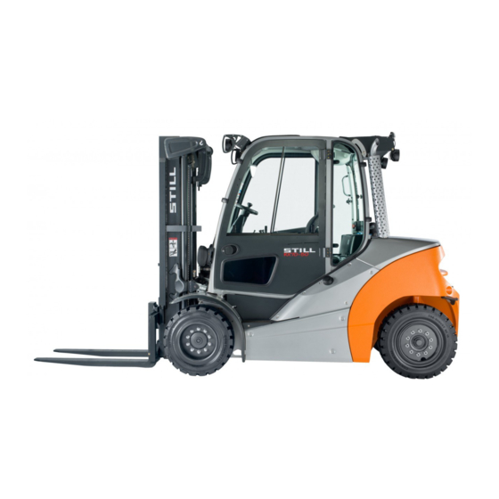
Page 62: Truck Overview
Overviews Truck overview Truck overview 7331_003-001 Lift mast Fuel tank locking cap Overhead guard Bonnet Driver’s compartment Drive axle Towing device Fork arms Steering axle Fork carriage 57348011825 EN - 12/2015... -
Page 63: Overview Of Driver's Compartment
Overviews Overview of driver’s compartment Overview of driver’s compartment Parking brake lever Bottle holder for max. 1.5 l bottles Steering wheel Driver’s seat Key switch Compartment Display and operating unit Filler cap for windscreen washer reservoir Compartment for the operating instructions Accelerator pedal Operating devices for hydraulic and drive Brake pedal... -
Page 64: Operating Devices And Display Elements
Overviews Operating devices and display elements Operating devices and display elements Display and operating unit 7314_003-043 Hazard warning system button Operating hours display Front windscreen wiper button Time display (digital) Working spotlight button Particle filter display Drive programme selector button Rotating beacon display Lighting button Interior lighting display... -
Page 65: Operating Devices For Hydraulic And Driving Functions
Overviews Operating devices and display elements – If you have any questions, please contact your authorised service centre. Operating devices for hydraulic and driving functions Different versions of the operating devices are available for operating the truck’s hydraulic and traction functions. The truck can be equipped with the following operating devices: •... -
Page 66: Double Mini-Lever
Signal horn button "Drive direction/turn indicator" cross lever NOTE Depending on the equipment, various electric attachment parts can be controlled via function keys (2) and (3). Changes must only be made by the STILL service centre. 57348011825 EN - 12/2015... -
Page 67: Three-Way Mini-Lever
"Drive direction/turn indicator" cross lever Signal horn button NOTE Depending on the equipment, various electric attachment parts can be controlled via function keys (2) and (3). Changes must only be made by the STILL service centre. 57348011825 EN - 12/2015... -
Page 68: Four-Way Mini-Lever
Signal horn button "Drive direction/turn indicator" cross lever NOTE Depending on the equipment, various electric attachment parts can be controlled via function keys (3) and (4). Changes must only be made by the STILL service centre. 57348011825 EN - 12/2015... -
Page 69: Joystick 4Plus
Overviews Operating devices and display elements Joystick 4Plus 6210_003-087 Horizontal rocker button for "3rd hydraulic LED for clamp locking mechanism (variant) function", tilt the lift mast Slider for the "4th hydraulic function", e.g. Pictograms for the basic hydraulic functions reach frame forwards/backwards Pictograms for the 5th hydraulic function and Vertical rocker button for the "drive direction"... -
Page 70: Fingertip
Right turn indicator button Drive direction switch Function key "5th function" NOTE Depending on the equipment, various electric attachment parts can be controlled via function keys (1) and (2). Changes must only be made by the STILL service centre. 57348011825 EN - 12/2015... -
Page 71: Identification Points
Overviews Identification points Identification points Overview Decal information: Lifting gear attachment Decal information: Tyre filling pressure point (variant), on both sides of the truck Manufacturer’s label text Decal information: Top up diesel fuel Warning sign: Danger due to shearing/Dan- Decal information: Armrest adjustment ger due to high fluid pressure Decal information: Lifting gear attachment Warning sign: Do not stand underneath the... -
Page 72: Nameplate
Overviews Identification points Decal information: FEM test with inspection sticker Nameplate The truck can be identified from the informa- tion on the nameplate. Type-Modèle-Typ / Serial no.-No. de série-Serien-Nr. / year-année-Baujahr Rated capacity Unladen mass Capacité nominale Masse à vide Nenn-Tragfähigkeit Leergewicht Battery voltage... -
Page 73: Production Number
Overviews Identification points Production number xx xxxx x xxxxx NOTE The production number is used to identify the truck. It can be found on the nameplate and must be referred to in all technical questions. The production number contains the following coded information: (1) Production location (2) Model... -
Page 74: Equipment
Overviews Equipment Equipment Accessories • Key for key switch (two pieces) • Key for cab (variant) • Hexagon socket wrench for emergency lowering 57348011825 EN - 12/2015... -
Page 75: Operation
Operation... -
Page 76: Checks And Tasks To Be Carried Out Prior To Commissioning
Operation Checks and tasks to be carried out prior to commissioning Checks and tasks to be carried out prior to commissioning Visual inspections WARNING Risk of accident due to damage or other defects on the truck or on the attachment (variant)! Damage to the truck or the attachment (variant) can lead to unpredictably dangerous situations. - Page 77 Operation Checks and tasks to be carried out prior to commissioning • Attachments (variant) must be properly mounted and function according to the operating instructions. • All decal information signs must be in place and legible. Replace damaged or missing adhesive labels in accordance with the overview in the "Identification points"...
-
Page 78: Checking The Side Cover Is Locked
Operation Checks and tasks to be carried out prior to commissioning Checking the side cover is locked – Check whether the side cover is locked, see ⇒ Chapter "Closing the side service flap", P. 6-305. Filling the washer system CAUTION Components may become damaged due to the effects of frost! Water expands when it freezes. -
Page 79: Checking The Condition Of The Wheels And Tyres
Operation Checks and tasks to be carried out prior to commissioning Checking the condition of the wheels and tyres WARNING Risk of accidents! With uneven wear or incorrect air pressure, the stability of the forklift truck decreases and the braking distance increases. –... -
Page 80: Topping Up The Coolant And Checking The Concentration Of The Coolant Additive
Operation Checks and tasks to be carried out prior to commissioning Topping up the coolant and checking the concentration of the coolant additive CAUTION Risk of engine damage! If the coolant level is low, this indicates a leak in the cooling system. -
Page 81: Checking The Engine Oil Level
Operation Checks and tasks to be carried out prior to commissioning Frost protection Water percentage Coolant additive percentage up to °C Filling quantity in the cooling system; see ⇒ Chapter "Maintenance data table", P. 6-291. CAUTION Coolant additive with a different specification must not be added! –... -
Page 82: Adjusting The Msg 65/Msg 75 Driver's Seat
Operation Checks and tasks to be carried out prior to commissioning Adjusting the MSG 65/MSG 75 driver’s seat DANGER There is a risk of accident if the seat or seat backrest shifts suddenly, which could cause the driver to move in an uncontrolled manner. This may result in unintentional actuation of the steering or operating devices and thus cause the truck or load to move in an uncontrolled fashion. - Page 83 Operation Checks and tasks to be carried out prior to commissioning Moving the driver’s seat – Lift and hold the lever (1) – Push the driver’s seat into the desired position. – Release the lever. – Ensure that the driver’s seat is securely engaged.
- Page 84 Operation Checks and tasks to be carried out prior to commissioning Adjusting the seat suspension NOTE The driver’s seat can be adjusted to suit the weight of the individual driver. In order to achieve the best seat suspension setting, the driver should perform the adjustment whilst sitting in the seat.
- Page 85 Operation Checks and tasks to be carried out prior to commissioning Adjusting the lumbar support (variant) NOTE The lumbar support can be adjusted to suit the contours of the individual driver’s spine. Adjusting the lumbar support moves a convex support cushion into the upper or lower part of the backrest.
-
Page 86: Adjusting The Armrest
Operation Checks and tasks to be carried out prior to commissioning Switching the seat heater (variant) on and off NOTE The seat heater only functions if the seat contact switch is active, i.e. when the driver is sitting on the driver’s seat. –... -
Page 87: Adjusting The Steering Column
Operation Checks and tasks to be carried out prior to commissioning – Tighten the hand wheel by turning it clock- wise. – Check that the armrest is firmly attached. Adjusting the steering column – Press down the steering column adjustment lever (2). -
Page 88: Commissioning
Operation Commissioning Commissioning Climbing into and out of the truck WARNING Risk of injury when climbing into and out of the truck due to slipping, striking parts of the truck or becoming stuck! If the footwell cover is very dirty or smeared with oil, there is a risk of slipping. -
Page 89: Climbing Into And Out Of A Truck With A Raised Driver's Cab
Operation Commissioning To assist with climbing into and out of the truck, the footwell must be used as a step (5) and the handle (1) must be used for support. The post of the overhead guard (2) can also be used for support. - Page 90 Operation Commissioning WARNING Risk of injury when jumping out of the truck! If your clothing or jewellery (e.g. watch, ring etc.) becomes stuck on a component while you are jumping out of the truck, this can lead to serious injuries (e.g. from falling, loss of fingers etc.). It is forbidden to jump out of the truck.
-
Page 91: Shelves And Cup Holders
Operation Commissioning – Grip the handle (2) with your left hand and do not let go. – Grip the handle (4) with your right hand and do not let go. – Place your right foot on the bottom step (5). –... -
Page 92: Unlocking The Emergency Off Switch
Operation Commissioning Unlocking the emergency off switch NOTE Only diesel trucks with a particle filter system (variant) or a joystick 4Plus (variant) have an emergency off switch. – Pull the emergency off switch (1) until it unlatches. 7312_003-183 Switching on the key switch WARNING Before switching on the key switch, all tests prior to start-up must be performed without detecting any... - Page 93 Operation Commissioning – Insert the switch key (1) into the key switch and turn to position "I" 7090_001-002 This initiates a self-test. All lamps in the drive direction and turn indicator displays light up briefly. 7312_003-085 57348011825 EN - 12/2015...
- Page 94 Operation Commissioning When the key switch is switched on, the display shows the welcome screen in the set language until the truck controls have completely started up. If the truck has the "access authorisation with PIN code" variant, the display initially changes to the input menu for access authorisation.
-
Page 95: Access Authorisation With Pin Code (Variant)
Operation Commissioning NOTE Additional information may appear on the display. If faults occur, refer to the information in the chapter entitled "Faults". Access authorisation with PIN code (variant) Description Trucks equipped with the "Access authori- sation with PIN code" variant are protected against unauthorised use by a five-digit driver PIN. - Page 96 The driver PINs are stored in the truck control unit. These are still available if the display and operating unit has been changed. The authorised service centre can use a diagnostic device to read out the driver PIN and, if necessary, restore the factory default driver PIN.
- Page 97 Operation Commissioning If an incorrect driver PIN is entered, the message appears for a short time. INVALID When the message goes out, the driver PIN can be re-entered. BQ_023_en_V2 After three invalid entry attempts, the mes- sage appears. The input is CODE DENIED then locked for five minutes before another attempt can be made.
- Page 98 Operation Commissioning Defining the driver PIN NOTE The driver PIN can only be defined by persons with the corresponding access authorisation, e.g. fleet managers. In order for the fleet manager to define the driver PIN, the confi- guration menu must be accessed. The confi- guration menu is password-protected.
- Page 99 Operation Commissioning appears in the display. CONFIGURATION – Use the drive program selection button (1) and the menu change button (3) to select menu. ACCESS CODE – Confirm your selection by pressing the button (2). ENTER BQ_31_en Selecting the driver PIN In the menu, there are fifty ACCESS CODE...
- Page 100 Operation Commissioning appears in the display. NEW CODE – Enter the desired driver PIN using the buttons (5). The digits entered do not appear in the display. Instead they are represented by circles in the field (6). NEW CODE appears in the display. CONFIRM submenu is used to confirm CONFIRM...
- Page 101 Operation Commissioning If the driver PIN entered in the sub- CONFIRM menu does not match the driver PIN entered previously in the submenu, the NEW CODE message will appear. INVALID The message will then disappear after a short time. The new driver PIN can be entered in submenu for further confirma- CONFIRM tion.
- Page 102 Operation Commissioning Changing the password It is recommended that you change the factory default password. NOTE The password can only be changed when the parking brake is applied. – Push the drive program selection button (1) and the menu change button (2) at the same time.
- Page 103 Operation Commissioning appears in the display. CONFIGURATION – Use the drive program selection button (1) and the menu change button (3) to select menu. PASSWORD – Confirm your selection by pressing the button (2). ENTER BQ_032_en appears in PASSWORD/PASSWORD LEVEL the display.
-
Page 104: Operating The Signal Horn
Operation Commissioning appears in the display. NEW CODE The four-digit password can be entered using the buttons (1). CAUTION Do not enter the password 1777! If this password is entered, the configuration op- tions for the fleet manager are restricted to driver authorisations and cannot be reset independently. -
Page 105: Seat Belt
Operation Commissioning – Push the signal horn button (1). The signal horn sounds. 7331_500-002 Seat belt DANGER Even when using an approved restraint system, there is some residual risk that the driver might be injured if the truck tips over. This risk of injury can be reduced through the combined use of the restraint system and the seat belt. - Page 106 Operation Commissioning Fastening the seat belt DANGER Risk to life when driving without a seat belt! If the truck tips over or crashes into an obstacle and the driver is not wearing the seat belt, the driver may be thrown from the truck. The driver could slide under the truck or collide with an obstacle.
- Page 107 Operation Commissioning Fastening on a steep slope The automatic blocking mechanism prevents the belt from being extended whenever the truck is on a steep gradient. It is not possible to pull the seat belt any further out of the belt retractor.
-
Page 108: Using The Driver's Cab
Operation Commissioning CAUTION The seat belt may be damaged by heat! Do not subject the buckle or belt retractor to exces- sive heat when thawing. – Do not use air warmer than 60°C when thawing. Using the driver’s cab DANGER Risk of fatal injury in the event of falling from the truck if it tips over! In order to prevent the driver from sliding under-... -
Page 109: Starting The Engine
Operation Commissioning Starting the engine DANGER Risk to health from exhaust gases! Exhaust gases from internal combustion engines are harmful to your health. In particular, the soot particles contained in the diesel exhaust gas can cause cancer. When the internal combustion engine is running, there is a risk of poisoning from the CO, CH and NOx components contained in the exhaust gas. - Page 110 Operation Commissioning display flashes, which indicates GLOW that the engine is being preheated. NOTE Preheating can take up to 20 seconds. If the engine is already at operating temperature, preheating is not performed. – If the message lights up on the START display, turn the switch key to position "II"...
-
Page 111: Checking The Brake System For Correct Function
Operation Commissioning Checking the brake system for correct function DANGER If the brake system fails, the truck is insufficiently braked or not braked at all, so there is a risk of accident! – Do not commission trucks with a defective brake system. -
Page 112: Checking The Steering System For Correct Function
Operation Commissioning Checking the steering system for correct function DANGER If the hydraulics fail, there is a risk of accident as the steering characteristics have changed. – Do not operate the truck if it has a defective steering system. – Operate steering wheel (1). The steering play while stationary must not be more than two finger widths. -
Page 113: Zero Adjustment Of The Load Measurement (Variant)
Operation Commissioning – Press the emergency off switch (1). The truck will coast – Brake the truck to a standstill by actuating the brake pedal. NOTE In trucks with an electric parking brake, the electric parking brake will be applied as soon as the truck comes to a stop. - Page 114 Operation Commissioning raise the fork more than 800 mm above the ground. NOTE Operation of the lifting system depends on which operating devices the truck is fitted with; see ⇒ Chapter "Lifting system operating devices", P. 5-128. – Set lift mast to vertical. –...
-
Page 115: Checking The Vertical Lift Mast Position (Variant) For Correct Function
Operation Commissioning Checking the vertical lift mast position (variant) for correct function NOTE The function check of the lift mast vertical position (variant) must be carried out every time a truck is commissioned. – Actuate function key (1) to switch on the comfort feature "lift mast vertical position". -
Page 116: Driving
Operation Driving Driving Safety regulations when driving Driving conduct The driver must follow the public rules of the road when driving in company traffic. The speed must be appropriate to the local conditions. For example, the driver must drive slowly around corners, in tight passageways, when driving through swing-doors, at blind spots, or on uneven surfaces. - Page 117 There is a risk of accident! – Do not use devices during travel or when hand- ling loads. – Set the volume so that warning signals can still be heard. WARNING In areas where use of mobile phones is prohibited, use of a mobile phone or radio telephone is not permitted.
-
Page 118: Roadways
For pallets, these are: 7321_003-019 with pallet with pallet Aisle width (mm) 800 x 1200 1000 x 1200 lengthwise crosswise RX70-40 3912 4112 RX70-45 3942 4142 RX70-50 4037 4237 The truck may only be used on roadways... - Page 119 Operation Driving to prevent the load from falling to the ground or the truck being damaged. Warning in case components project beyond the truck contour Trucks are often required to drive through very narrow or very low spaces such as aisles or containers.
-
Page 120: Setting The Drive Programmes
Operation Driving Hazard areas Hazardous areas on the roadways must be marked by standard traffic signs or, if necessary, by additional warning signs. Setting the drive programmes The driving and braking characteristics of the drive can be set on the display and operating unit. -
Page 121: Actuating The Drive Direction Switch, Mini-Lever Version
Operation Driving Actuating the drive direction switch, mini-lever version – For the "forwards" drive direction, push the cross lever (1) forwards – For the "backwards" drive direction, push the cross lever backwards 5060_003-096 Actuating the vertical rocker switch for the "drive direction", joy- stick 4Plus version –... -
Page 122: Actuating The Drive Direction Switch, Fingertip Version
Operation Driving Actuating the drive direction switch, fingertip version – For the "forwards" drive direction, push the drive direction switch (1) forwards – For the "backwards" drive direction, push the drive direction switch backwards 7325_003-031 Starting to drive DANGER Being trapped under a rolling or tipping truck could cause fatal injuries. - Page 123 Operation Driving The indicator for the selected drive direction ("forwards" (1) or "backwards" (2)) lights up on the display and operating unit. NOTE Depending on the equipment, an acoustic signal (variant) may sound a warning during reverse travel, the warning light (variant) may light up or the hazard warning system (variant) may flash.
-
Page 124: Starting Drive Mode, Dual-Pedal Version (Variant)
The truck cannot be driven again until the accelerator pedal has been released and then actuated again, provided the electrical fault has been corrected. If the truck still won’t operate, park it securely and contact your service centre. Starting drive mode, dual-pedal version (variant) - Page 125 Operation Driving – Press the right accelerator pedal (1) to drive "forwards" and press the left accelerator pedal (2) to drive "backwards". NOTE In the dual pedal version, any drive direction switches on the operating devices have no effect. 5060_003-085 The indicator for the selected drive direction ("forwards"...
- Page 126 The truck cannot be driven again until the accelerator pedal has been released and then actuated again, provided the electrical fault has been corrected. If the truck still won’t operate, park it securely and contact your service centre. 57348011825 EN - 12/2015...
-
Page 127: Operating The Service Brake
Operation Driving Operating the service brake The electric brake converts the acceleration energy of the truck into electrical energy. This causes the truck to decelerate. In addition, the truck can be braked using the service brake: – Press the brake pedal (2). In the first section of the brake pedal’s travel, only the regenerative braking takes effect. -
Page 128: Actuating The Mechanical Parking Brake
Operation Driving Zero braking (variant) DANGER Risk of accident! Trucks with zero braking (variant) are not braked when the accelerator pedal is released. – Bring the truck to a standstill by actuating the brake pedal. If your truck features the zero braking equip- ment variant, the electric brake function is disabled. - Page 129 Operation Driving Apply the parking brake – Pull the parking brake lever (1) down fully and release. The parking brake lever swivels back half the distance into the middle position automati- cally. The parking brake is engaged and the wheels are blocked.
-
Page 130: Steering
Operation Driving Steering DANGER If the hydraulics fail, there is a risk of accident as the steering characteristics have changed. – Do not operate the truck if it has a defective steering system. – Steer the truck by turning the steering wheel (1) accordingly. -
Page 131: Reducing Speed With A Raised Load (Variant)
Operation Driving Reducing speed with a raised load (variant) This function (variant) reduces the speed of the truck with a raised load. 7321_003-052_en_V2 Automatic shut-off of the internal combustion engine (variant) The truck is equipped with an automatic shut-off function that shuts off the internal combustion engine when certain conditions apply simultaneously and after a preset STOP... -
Page 132: Lifting
Operation Lifting Lifting Lifting system variants The movement of the fork carriage and the lift mast heavily depends on the following equipment: • The lift mast with which the truck is equipped, see ⇒ Chapter "Types of lift mast", P. 5-125 •... -
Page 133: Lift Mast Vertical Position (Variant)
Operation Lifting Overriding and reactivating the auto- matic lift cut out If a load needs to be lifted to the truck’s maximum lift height and the automatic lift cut out function is not required, it is possible to override the lift cut out. It is automatically reactivated when the truck is switched off and back on again. - Page 134 Operation Lifting CAUTION Risk of damage to property due to the lift mast colliding with racks or other objects! – Before using the "lift mast vertical position" comfort feature, position the truck at a sufficient distance from racks and other objects. The "lift mast vertical position"...
- Page 135 Operation Lifting Display of the "lift mast vertical position" The driver can see the mast tilt on the display and operating unit screen. The bar in the display shows the current mast tilt relative to the "lift mast vertical position". The arrow above the bar marks the vertical position of the lift mast.
- Page 136 Operation Lifting Tilting the lift mast forwards with the "lift mast vertical position" – Actuate the button (1) to switch on the "lift mast vertical position" comfort feature; the function display (2) in the display shows the activated status. – Tilt the lift mast forwards. NOTE The way in which the lifting system is operated depends on the operating devices included in...
-
Page 137: Types Of Lift Mast
Operation Lifting Possible restrictions on the "lift mast vertical position" In some circumstances, the lift mast cannot move exactly into the preset vertical position. Possible causes include: • Uneven ground • Bent fork • Bent attachment • Worn tyres • Severely deformed lift mast The vertical position can be corrected by tilting the lift mast using the relevant operating device. -
Page 138: Malfunctions During Lifting Mode
Operation Lifting Telescopic mast During lifting, the lift mast rises over the outer lift cylinders, bringing the fork carriage with it via the chains (fork carriage rises twice as fast as the inner lift mast). The top edge (1) of the inner lift mast can therefore be higher than the fork carriage. - Page 139 Operation Lifting An incorrect extension sequence may, for instance, result from: • The hydraulic oil temperature being too low. • The fork carriage becoming blocked in the inner lift mast. • Blocking of the free lift cylinder. • The chain roller becoming blocked at the free lift cylinder.
-
Page 140: Hydraulic Blocking Function
Operation Lifting Hydraulic blocking function The hydraulic blocking function ensures that all hydraulic functions are disabled whenever the seat switch in the driver’s seat is unloaded. This is when the driver stands up from the driver’s seat or exits the truck. All hydraulic functions are disabled in this case: •... - Page 141 Operation Lifting DANGER Reaching into or climbing between moving parts of the truck (e.g. lift mast, sideshifts, working equipment, load carrying devices etc.) can lead to serious injury or death and is therefore prohibited. – Observe the safety regulations for handling loads.
-
Page 142: Controlling The Lifting System Using A Double Mini-Lever
Operation Lifting Controlling the lifting system using a double mini-lever DANGER Reaching into or climbing between moving parts of the truck (e.g. lift mast, sideshifts, working equipment, load carrying devices etc.) can lead to serious injury or death and is therefore prohibited. –... -
Page 143: Controlling The Lifting System Using A Triple Mini-Lever
Operation Lifting Controlling the lifting system using a triple mini-lever DANGER Reaching into or climbing between moving parts of the truck (e.g. lift mast, sideshifts, working equipment, load carrying devices etc.) can lead to serious injury or death and is therefore prohibited. –... -
Page 144: Controlling The Lifting System Using A Quadruple Mini-Lever
Operation Lifting Controlling the lifting system using a quadruple mini-lever DANGER Reaching into or climbing between moving parts of the truck (e.g. lift mast, sideshifts, working equipment, load carrying devices etc.) can lead to serious injury or death and is therefore prohibited. –... -
Page 145: Controlling The Lifting System Using The Joystick 4Plus
Operation Lifting Controlling the lifting system using the joystick 4Plus DANGER Reaching into or climbing between moving parts of the truck (e.g. lift mast, sideshifts, working equipment, load carrying devices etc.) can lead to serious injury or death and is therefore prohibited. –... - Page 146 Operation Lifting Fork-carriage sideshift To move the fork carriage to the left. – Push the joystick 4Plus (1) to the left (E). To move the fork carriage to the right: – Push the joystick 4Plus (1) to the right (F). NOTE The symbols on the joystick 4Plus indicate the direction of movement of the lift mast or the...
-
Page 147: Controlling The Lifting System Using The Fingertip
Operation Lifting Controlling the lifting system using the fingertip DANGER Reaching into or climbing between moving parts of the truck (e.g. lift mast, sideshifts, working equipment, load carrying devices etc.) can lead to serious injury or death and is therefore prohibited. –... -
Page 148: Changing The Fork Arms
Operation Lifting Changing the fork arms DANGER There is a risk of being run over if the truck rolls away, and therefore a danger to life. – Do not park the truck on a gradient. – Apply the parking brake. –... - Page 149 Operation Lifting Removal – Select a pallet corresponding to the fork arm size. – Position the pallet to the left or right of the fork carriage. – Raise the fork carriage until the lower edges of the fork arms are approx.3 cm higher than the height of the pallet.
-
Page 150: Fork Extension (Variant)
Operation Lifting Fork extension (variant) DANGER There is a risk of being run over if the truck rolls away and therefore a danger to life. – Do not park the truck on a slope. – Apply the parking brake. – Change the fork extension in a separate, safe location on a level surface. - Page 151 Operation Lifting Attachment DANGER Risk to life from falling load! At least 60% of the length of the fork extension must lie on the fork arm. A maximum 40% overhang over the fork arm end is permissible. The fork extension must also be secured against slipping from the fork arm.
-
Page 152: Operation With Reversible Fork Arms (Variant)
Operation Lifting Operation with reversible fork arms (variant) DANGER Risk to life from falling load! Standard fork arms are not structurally designed for reverse operation. If this instruction is not observed, it can lead to material failure and the load falling. –... - Page 153 Operation Lifting Reversible fork arms (1) can be used to reach an additional lift height. The reversible fork arms are installed on the fork carriage in the same manner as standard fork arms. Loads may be lifted on and beneath the reversible fork arms.
-
Page 154: Handling Loads
Operation Handling loads Handling loads Safety regulations when handing loads The safety regulations for handling loads are shown in the following sections. DANGER There is a risk to life caused by falling loads or if parts of the truck are being lowered. –... -
Page 155: Before Taking Up Load
Operation Handling loads Before taking up load Load capacity The load capacity indicated for the truck on the capacity rating plate may not be exceeded. The load capacity is influenced by the load centre of gravity and the lift height as well as by the tyres, if applicable. -
Page 156: Load Measurement (Variant)
Operation Handling loads Example Weight of load to be lifted: 880 kg (3) Load distance from fork back: 500 mm (1) Permitted lift height: 5230 mm (2) WARNING Risk of accident from the truck losing stability! The permissible load of the attachments (variant) and the reduced lifting capacity of the combination 5230 of truck and attachment must not be exceeded. - Page 157 Operation Handling loads The load measurement has an accuracy of +/-3% of the rated capacity of the truck. NOTE In order to ensure accuracy at all times, a zero adjustment of the load measurement must be carried out. Zero adjustment is required. as part of daily commissioning •...
- Page 158 Operation Handling loads NOTE The method of operating the lifting system depends on the operating devices included in the truck’s equipment. – Ensure that the truck has been in operation for a period of time before carrying out the load measurement. –...
-
Page 159: Picking Up Loads
Operation Handling loads When the load measurement has been carried out correctly, the determined load weight is displayed in the operating unit. NOTE If the load measurement is invalid, the value "-9999 kg" is displayed in the operating unit. 6210_003-073_en Picking up loads To make sure that the load is securely sup- ported, it must be ensured that the fork arms... -
Page 160: Danger Area
Operation Handling loads Adjusting the fork – Lift the locking lever (1) and move the fork arms to the desired position. – Allow the locking lever to snap back into place. The load centre of gravity must be midway between the fork arms. –... -
Page 161: Transporting Pallets
Operation Handling loads DANGER Danger of death from falling loads! – Never walk or stand underneath suspended loads. Transporting pallets As a rule, loads (e.g. pallets) must be transpor- ted individually. Transporting multiple loads at the same time is only permitted: •... -
Page 162: Load Pick Up
Operation Handling loads DANGER Loss of stability. Slipping or swinging suspended loads can lead to a loss of stability and cause the truck to tip over. – When transporting suspended loads, observe the following instructions Instructions for transporting suspended loads: •... - Page 163 Operation Handling loads – Only store pallets which do not exceed the specified maximum size. Damaged loading equipment and incorrectly formed loads must not be stored. – Attach or secure the load to the load- carrying equipment so that the load cannot move or fall.
- Page 164 Operation Handling loads – Insert the fork as far under the load as possible. Stop the truck as soon as the fork back is resting on the load. The centre of gravity of the load must be positioned between the fork arms in the middle. 6210_800-007 –...
- Page 165 Operation Handling loads – Lower the load while maintaining ground clearance. 5060_003-102 – Tilt the lift mast backwards. The load can be transported. 5060_003-101 57348011825 EN - 12/2015...
-
Page 166: Transporting Loads
Operation Handling loads Transporting loads NOTE Observe the information in the chapter entitled "Safety regulations when driving". DANGER The higher a load is lifted, the less stable it beco- mes. The truck can tip over or the load can fall, increasing the risk of accident! Driving with a raised load and the lift mast tilted forward is not permitted. -
Page 167: Setting Down Loads
Operation Handling loads – Never drive with a load protruding to the side (e.g. with the sideshift)! 6210_800-014 Setting down loads DANGER Risk of accident due to changed moment of tilt! Please note that the lift mast can be tilted far enough forward with a raised load to cause the truck to tip over. -
Page 168: Shake Function (Variant)
Operation Handling loads load capacity diagram must be created as the stability will be affected. Contact the authorised service centre on • this matter. – Drive up to the stack with the load lowered in accordance with regulations. – Set lift mast to vertical. –... - Page 169 Operation Handling loads NOTE The shake function is only intended for short- term use as it reduces the service life of the load chains due to increased strain. Operation To activate the shake function: – Move the corresponding operating device for the "Lifting"...
- Page 170 Operation Handling loads on the operating device, the shake function is also activated via this other assignment. Joystick 4Plus: – Move the joystick 4Plus (1) back and forth four times between positions (A) and (B). Then continue to move the component in the same way.
- Page 171 Operation Handling loads Triple mini-lever: – Move the 360° lever (3) back and forth four times between positions (A) and (B). Then continue to move the component in the same way. Quadruple mini-lever: – Move the operating lever (4) back and forth four times between positions (A) and (B).
-
Page 172: Driving On Ascending And Descending Slopes
Operation Handling loads Fingertip switch: – Move the operating lever (5) back and forth four times. Then continue to move the component in the same way. Driving on ascending and descend- ing slopes DANGER Danger to life! On ascending and descending slopes the load must be carried facing uphill. -
Page 173: Driving On Lifts
Operation Handling loads Driving on lifts The driver may only use this truck on lifts with a sufficient rated capacity and for which the operating company has been granted authorisation. DANGER There is a risk to life if you are crushed or run over by the truck. -
Page 174: Driving On Loading Bridges
Operation Handling loads Driving on loading bridges DANGER Risk of accident if the truck crashes! Steering movements can cause the tail end to veer off the loading bridge towards the edge. This may cause the truck to crash. The lorry driver and the truck driver must agree on the lorry’s departure time. -
Page 175: Particle Filter System
Operation Particle filter system Particle filter system Particle filter - Function DANGER Risk to health from exhaust gases! Exhaust gases from internal combustion engines are harmful to your health. In particular, the soot particles contained in the diesel exhaust gas can cause cancer. - Page 176 Operation Particle filter system In addition, very low ambient temperatures may prevent a sufficiently high exhaust gas temperature being reached. This causes the regeneration process to be disrupted. The soot filtered out of the exhaust gas then collects in the particle filter, as it is not burned off during the continuous regeneration process.
-
Page 177: Particle Filter - Performing Parked Regeneration
Operation Particle filter system Particle filter - Performing parked regeneration CAUTION Risk of damage to components! If parked regene- ration is not performed when required, the particle filter may become damaged. A full parked regeneration must be performed in order to completely empty the particle filter. CAUTION During the parked regeneration process, very hot combustion gases escape from the exhaust pipe! - Page 178 Operation Particle filter system • Remove any connected exhaust gas extraction units • Perform parked regeneration in a suitable place NOTE Parked regeneration can only be performed if the parking brake is engaged. If the parking brake is not engaged, APPLY HANDBRAKE! appears on the display.
- Page 179 Operation Particle filter system The message as well START PARK. REG.? as the soft keys (1) and (2) appear on the display. – To start the parked regeneration process, press the button (1). The message appears START IC ENGINE on the display. –...
-
Page 180: Particle Filter - Displays
Operation Particle filter system The particle filter regeneration process is started. EXH.GAS PURIFIER PLEASE appears on the display. The status WAIT bar (4) below the message indicates the regeneration progress. NOTE During parked regeneration, the engine speed fluctuates and the power of the radiator fan is reduced. - Page 181 Operation Particle filter system relating to parked regeneration and if parked regeneration is not performed: Messages Meaning Comment Carry out parked regeneration See the section entitled "Per- EXH.GAS PURIFIER of the particle filter. forming parked regeneration" Prompt asking whether parked START regeneration of the particle PARK.
-
Page 182: Working With Attachments
Fitting attachments If the truck is equipped with an integrated attachment (variant) at the factory, the specifi- cations in the STILL operating instructions for integrated attachments must be observed. If attachments are fitted at the place of use, the specifications in the operating instructions of the attachment manufacturer must be observed. - Page 183 Operation Working with attachments DANGER There is risk to life caused by a falling load! Attachments that hold the load by exerting pressure on it (e.g. clamps) must be controlled additionally by a second operating function (lock) that is actuated to prevent an unintentional release of the load.
-
Page 184: Releasing The Pressure From The Hydraulic System
Operation Working with attachments Load capacity with attachment The permissible load capacity of the attach- ment and the allowable load (load capacity and load moment) of the truck must not be ex- ceeded by the combination of attachment and payload. The specifications of the manufac- turer and supplier of the attachment must be complied with. - Page 185 Operation Working with attachments – Actuate the operating lever (1) for control- ling the hydraulic functions repeatedly in the direction of the arrow, as far as the end position. The valves open and the hydraulic system is depressurised. – Switch off the key switch. 7312_003-184 57348011825 EN - 12/2015...
-
Page 186: General Instructions For Controlling Attachments
Operation Working with attachments General instructions for controlling attachments The way in which attachments (variant) are controlled depends on the operating devices included in the truck’s equipment. Essentially, a distinction is drawn between: • Double mini-lever • Double mini-lever with a 5th function (variant) •... - Page 187 Operation Working with attachments NOTE All the attachments described fall into the category of equipment variants. Please see the respective operating instructions for an exact description of the respective movements/actions of the attachment fitted. 57348011825 EN - 12/2015...
-
Page 188: Controlling Attachments Using A Double Mini-Lever
Operation Working with attachments Controlling attachments using a double mini-lever The attachments (variants) are controlled in this version using the "attachments" cross lever (1). The pictograms on the "attachments" cross lever show the respective functions that are activated by this lever. This essentially involves the following: –... - Page 189 Operation Working with attachments – Note the following attachment functions and pictograms. Move sideshift frame or fork forwards Move sideshift frame or fork back- wards Move sideshift to the left Move sideshift to the right Adjust fork arms: open Adjust fork arms: close Swivel lift mast or fork to the left Swivel lift mast or fork to the right Release load retainer...
-
Page 190: Controlling Attachments Using The Double Mini-Lever And The 5Th Function
Operation Working with attachments Controlling attachments using the double mini-lever and the 5th function NOTE The "lift mast" 360° lever and the "attach- ments" cross lever control four hydraulic func- tions. The "5th function" designation refers to the fact that switching functions using the "5th function"... - Page 191 Operation Working with attachments – Note the following attachment functions and pictograms. Move sideshift frame or fork forwards Move sideshift frame or fork back- wards Move sideshift to the left Move sideshift to the right Adjust fork arms: open Adjust fork arms: close Swivel lift mast or fork to the left Swivel lift mast or fork to the right Release load retainer...
-
Page 192: Controlling Attachments Using A Triple Mini-Lever
Operation Working with attachments Controlling attachments using a triple mini-lever The attachments (variant) are controlled in this version using operating levers (1) and (2). The pictograms on the operating levers show the respective functions that are activated by these levers. This essentially involves the following: –... - Page 193 Operation Working with attachments – Note the following attachment functions and pictograms! Move sideshift frame or fork forwards Move sideshift frame or fork back- wards Move sideshift to the left Move sideshift to the right Adjust fork arms: open Adjust fork arms: close Swivel lift mast or fork to the left Swivel lift mast or fork to the right Release load retainer...
-
Page 194: Controlling Attachments Using The Triple Mini-Lever And The 5Th Function
Operation Working with attachments – Actuate the "5th function" function key (3) and move operating lever (1) towards (E) The attachment moves in accordance with the pictogram in position (E). – Actuate the "5th function" function key (3) and move operating lever (1) towards (F) The attachment moves in accordance with the pictogram in position (F). -
Page 195: Controlling Attachments Using A Quadruple Mini-Lever
Operation Working with attachments Controlling attachments using a quadruple mini-lever The attachments (variant) are controlled in this version using operating levers (1) and (2). The pictograms on the operating levers show the respective function that is activated by these levers. This essentially involves the following: –... - Page 196 Operation Working with attachments – Note the following attachment functions and pictograms! Move sideshift frame or fork forwards Move sideshift frame or fork back- wards Move sideshift to the left Move sideshift to the right Adjust fork arms: open Adjust fork arms: close Swivel lift mast or fork to the left Swivel lift mast or fork to the right Release load retainer...
-
Page 197: Controlling Attachments Using The Quadruple Mini-Lever And The 5Th Function
Operation Working with attachments – Actuate the "5th function" function key (5) and move operating lever (3) towards (E) The attachment moves in accordance with the pictogram in position (E). – Actuate the "5th function" function key (5) and move operating lever (3) towards (F) The attachment moves in accordance with the pictogram in position (F). -
Page 198: Controlling Attachments Via The Joystick 4Plus
Operation Working with attachments Controlling attachments via the joystick 4Plus In this equipment, the attachments (variant) are controlled via the joystick 4Plus (1). The pictograms on the decal information about operation of the joystick 4Plus show the respective functions that are activated by the individual operating devices of the joystick 4Plus. -
Page 199: Controlling Attachments Using The Joystick 4Plus And The 5Th Function
Operation Working with attachments Controlling attachments using the joystick 4Plus and the 5th function – Note the following attachment functions and pictograms. Operating Function of the device attachment Horizontal Release/open clamp rocker button + shift button "F" NOTE 6210_003-096 The 5th hydraulic function can be used to control an attachment. -
Page 200: Controlling The Attachments With The Fingertip
Operation Working with attachments Controlling the attachments with the fingertip The attachments (variant) are controlled in this version using the operating levers (1). The pictograms on the operating levers show the functions that are activated by that lever. – Move the operating lever (1) forwards The attachment moves in the direction of movement shown in the upper part of the pictogram. -
Page 201: Controlling Attachments With The Fingertip And 5Th Function
Operation Working with attachments Controlling attachments with the fingertip and 5th function NOTE The designation "5th function" refers to the fact that the four operating levers control four functions, while the "5th function" can be controlled by switching functions. The attachments (variant) are controlled using the operating levers (1). - Page 202 Operation Working with attachments – Press function key (4) NOTE The arrow (5) under the function key indicates which operating lever is equipped with the "5th function". The "5th function" is switched to the 3rd operating lever; see sticker (6). 7325_003-045 –...
-
Page 203: Clamp Locking Mechanism (Variant)
Operation Working with attachments – Note the following attachment functions and pictograms! Move side shift frame or fork for- wards/backwards Move sideshift to the left/right Adjust fork arms: open/close Swivel lift mast or fork to the left/right Release/clamp load retainer Push off/pull in load Open/close clamps Turn to the left/right... - Page 204 Operation Working with attachments Double mini-lever – To release the clamp locking mechanism, push the cross lever (1) forwards. The LED for button F2 (2) lights up as long as the clamp locking mechanism is released. NOTE The hydraulic function for opening the clamp is available for one second after the clamp locking mechanism is released.
- Page 205 Operation Working with attachments – To operate clamping attachments, see the section entitled "Controlling attachments using the triple mini-lever and the 5th function". Quadruple mini-lever – To release the clamp locking mechanism, push the operating lever (1) forwards. The LED for button F2 (2) lights up as long as the clamp locking mechanism is released.
- Page 206 Operation Working with attachments Joystick 4Plus – To release the clamp locking mechanism, press and hold shift key "F"(3) and move the horizontal rocker button (1) to the right. – Keep shift key "F"(3) pressed and move the horizontal rocker button (1) back to the neutral position.
-
Page 207: Taking Up A Load Using Attachments
Operation Working with attachments Fingertip switch – To release the clamp locking mechanism, push the operating lever (1) forwards. The LED for button F2 (2) lights up as long as the clamp locking mechanism is released. NOTE The hydraulic function for opening the clamp is available for one second after the clamp locking mechanism is released. -
Page 208: Operating Auxiliary Equipment
Operation Operating auxiliary equipment – The rating plates show the permissible values for: • Load capacity Q (kg) (1) • Lift height h (mm) (2) • Load distance C (mm) (3) Operating auxiliary equipment Switching the lighting on and off Driving lights –... -
Page 209: Switching The Rotating Beacon On And Off
Operation Operating auxiliary equipment Working spotlights – To switch on the working spotlights (front and rear), press the button (1). The working spotlights light up. – To switch off the working spotlights, press the button (1) again. The working spotlights go out. NOTE On the version with StVZO (German Road Traffic Licensing Regulations) equipment,... -
Page 210: Switching The Hazard Warning System On And Off
Operation Operating auxiliary equipment Switching the hazard warning system on and off – Push the button (1) to switch on the hazard warning system. All direction indicators and indicator lights (2) flash. NOTE Pushing the button again switches the hazard warning system off again. - Page 211 Operation Operating auxiliary equipment The direction indicators and the correspon- ding direction indicator lights (2) or (3) flash. – Switch off the direction indicators by moving the cross lever to the centre position. 5060_003-012_V2 Fingertip version – Switch on the direction indicators by moving the corresponding turn indicator button (1) to the left or to the right.
- Page 212 Operation Operating auxiliary equipment The direction indicators and the correspon- ding direction indicator lights (2) or (3) flash. – Turn off the direction indicators by pushing the other turn indicator button. 5060_003-012_V2 Mini-console version – Switch on the direction indicators by moving the turn indicator switch (1) to the left or to the right.
-
Page 213: Switching The Double Working Spotlights On And Off
Operation Operating auxiliary equipment The direction indicators and the correspon- ding turn indicator displays (2) or (3) flash. – Switch off the direction indicators by moving the turn indicator switch to the centre position. 5060_003-012_V2 Switching the double working spotlights on and off. The double working spotlights are fitted up on the front right and left on the overhead guard. - Page 214 Operation Operating auxiliary equipment – Turn the key switch to position "I". – Press button (1). NOTE Pressing the button again switches the work- ing spotlights off again. Switching the upper working spotlights on/off automatically – Turn the key switch to position "I". –...
-
Page 215: Operating The Windscreen Wiper/Washer
Operation Operating auxiliary equipment The lower working spotlights light up. The upper working spotlights are switched on by the proximity switch when the fork carriage reaches or exceeds the preset lift height. The upper working spotlights are switched off by the proximity switch when the fork carriage falls below the preset lift height again. -
Page 216: Accident Recorder (Variant)
This data can be electronically read out and evaluated. For further informa- tion, contact your STILL service centre. Driver restraint systems (variants) Different driver restraint systems are available as variants for this truck. The description and operation for these systems can be found in the separate "Driver restraint systems"... -
Page 217: Closing The Cab Door
Operation Cab operation Closing the cab door DANGER There is a risk of damage caused by collision if the cab door opens while driving. – The cab door must be latched securely in the engaged position. Opening the side windows WARNING There is a risk of crushing between the window frame and side window from the side windows... -
Page 218: Closing The Side Windows
Operation Cab operation Closing the side windows WARNING There is a risk of crushing between the window frame and side window from the side windows slipping inadvertently during travel. – Make sure that the handle engages securely in the corresponding stop slot. Closing the rear side window: –... -
Page 219: Operating The Rear Window Heating
There is a risk of accident! – Do not use the radio when driving or when handling loads. 6321_003-015 – Set the radio volume so that you can still hear warning signals. 57348011825 EN - 12/2015... -
Page 220: Heating System (Variant)
Operation Cab operation Heating system (variant) DANGER Risk of explosion! Do not expose spray cans or gas cartridges to the flow of hot air. The heater should not be operated near storage rooms or similar facilities where fuel vapours or coal, wood or grain dust could accumulate. -
Page 221: Air Conditioning (Variant)
Operation Cab operation Adjusting the air flow – Adjust air flow at the front outlet vents (3) and the outlet vent in the footwell (4). 7331_345-002 Air conditioning (variant) Switching on the air conditioning – Switch the blower switch (1) on. –... -
Page 222: Trailer Operation
Operation Trailer operation Trailer operation Towed load DANGER There is an increased risk of accident when using a trailer. Using a trailer changes the truck handling charac- teristics. When towing, operate the truck such that the trailer train can be safely driven and braked at all times. -
Page 223: Coupling Pin In The Counterweight
Operation Trailer operation CAUTION Risk of damage to components! A support load is not permitted. – Do not use trailers with tillers supported by the tow coupling. This truck is suitable for the occasional towing of trailers. If the truck is equipped with a towing device, this occasional towing must not exceed 2% of the daily operating time. - Page 224 Operation Trailer operation – Push the coupling pin (2) down, turn 90° and pull out. – Adjust tiller height. DANGER Persons may become trapped between the truck and trailer. When hooking up, ensure that no one is between the truck and trailer. –...
-
Page 225: Automatic Tow Coupling
Operation Trailer operation – Push the coupling pin (2) down, turn 90° and pull out. – Slowly move the truck forwards and guide the tow-bar eye completely out of the counterweight. – Insert the coupling pin into the counter- weight, press downwards against the spring pressure and turn 90°... - Page 226 Operation Trailer operation DANGER If you briefly leave the truck to couple or uncouple the trailer, there is a risk to life caused by the truck rolling away and running you over. – Apply the parking brake. – Lower the forks to the ground. –...
- Page 227 Operation Trailer operation WARNING Risk of component damage if the tiller in the tow coupling is tilted! The tiller should be kept as horizontal as possible when towing. This ensures that the rotation range is sufficient at the top and bottom. The authorised service centre can adjust the assembly height for the tow coupling to the tiller height if necessary.
- Page 228 Operation Trailer operation DANGER If the coupling pin drops out during towing, the trailer will work loose and can no longer be controlled. There is a risk of accident! A protruding safety handle means that the tow bar eye has not been coupled correctly. The trailer must not be towed in this condition.
- Page 229 Operation Trailer operation Coupling model RO*244 A NOTE Trailer coupling RO 244 is intended for a tow bar eye in accordance with DIN 74054 (bore diameter 40 mm) or DIN 8454 (bore diameter 35 mm). – Take measures to prevent the trailer from rolling away, e.g.
- Page 230 Operation Trailer operation DANGER If the coupling pin drops out during towing, the trailer will work loose and can no longer be controlled. There is a risk of accident! The control pin (3) must not protrude out of its guide. –...
- Page 231 Operation Trailer operation NOTE To protect the lower coupling pin bush against contamination, always keep the tow coupling closed. Coupling model RO*245 NOTE Trailer coupling RO 245 is intended for a tow-bar eye in accordance with DIN 74054 (bore diameter 40 mm) or DIN 8454 (bore diameter 35 mm).
- Page 232 Operation Trailer operation Uncoupling model RO*245 – Take measures to prevent the trailer from rolling away, e.g. use wheel chocks. – Push the hand lever (5) upwards. – Slowly drive the truck forwards until the tow- bar eye and towing jaws are disconnected. –...
-
Page 233: Towing Trailers
Operation Trailer operation DANGER If the coupling pin drops out during towing, the trailer will work loose and can no longer be controlled. There is a risk of accident! A protruding safety handle means that the tow bar eye has not been coupled correctly. The trailer must not be towed in this condition. - Page 234 Operation Trailer operation NOTE Please observe the definition of the following responsible persons: "operating company" and "driver". 57348011825 EN - 12/2015...
-
Page 235: Operating The Display And Operating Unit
Operation Operating the display and operating unit Operating the display and operating unit Displays Standard display elements In the factory setting, the following indicators can be seen in the display and operating unit: Fuel level Shows the fuel level in the fuel tank in %. Drive programme Displays the current drive programme numerically (1-5). -
Page 236: Adjusting The Displays
Operation Operating the display and operating unit Adjusting the displays NOTE The parking brake must always be engaged when you adjust the displays. The displays cannot be adjusted if the parking brake is not engaged. NOTE When adjusting the displays, do not actuate the hydraulic system operating devices. - Page 237 Operation Operating the display and operating unit Symbols for operating messages Description Symbol Empty field No display Please wait Service required Lift limitation Reference cycle Battery charging Drive program Hour meter Odometer Daily hour meter Daily odometer Speed Steering angle Load Time Hydraulic system...
- Page 238 Operation Operating the display and operating unit Description Symbol Are you sure? Oil pressure Symbols for error messages Description Symbol Brake system malfunction Overheating of the engine Overheating Malfunction in the electrical system General malfunction Symbols for auxiliary equipment soft key functions For the auxiliary equipment, the following symbols for the soft key functions are used on...
- Page 239 Operation Operating the display and operating unit Description Symbol Heater blower OFF Heater blower ON Rotating beacon OFF Rotating beacon ON Seat heater OFF Seat heater ON Signal horn OFF Signal horn ON Symbols for the soft key functions for menu navigation and for acknowledging messages For menu navigation and to acknowledge...
- Page 240 Operation Operating the display and operating unit Description Function off LED OFF Function on LED ON Symbols for numeric keypad The available inputs and the positions of the keys are shown for inputting digits, ENTER Keys for the digits 1 to 7 and the keys for inputting the fleet manager ENTER password...
-
Page 241: Setting The Date Or Time
Operation Operating the display and operating unit Setting the date or time – Switch to the "CONFIGURATION" menu; see ⇒ Chapter "Adjusting the dis- plays", P. 5-224. – Press the drive program key (1) or menu selection key (2) until the option TIME appears.Confirm your selection by pressing the Return key (4). -
Page 242: Setting The Language
Operation Operating the display and operating unit NOTE The daily operating hours are reset in the same manner. Setting the language 1 2 3 4 The displays can be shown in additional languages: – Switch to the "CONFIGURATION" menu; see ⇒ Chapter "Adjusting the dis- plays", P. -
Page 243: Configuring Blue-Q Efficiency Mode
Operation Operating the display and operating unit A grey bar (3) highlights the active soft key column, i.e. the soft keys in this column can be operated. To change the soft key column: – Briefly press the "Menu change button"(1). The grey bar jumps to the other soft key column. -
Page 244: Additional Settings
Operation Operating the display and operating unit – Switch to the menu; CONFIGURATION see ⇒ Chapter "Adjusting the dis- 1 2 3 4 plays", P. 5-224 – Keep pressing the drive programme button (1) or the menu change button (2) until op- tion appears. -
Page 245: Blue-Q Efficiency Mode
Operation Blue-Q efficiency mode Blue-Q efficiency mode Functional description The Blue-Q efficiency mode affects both the drive unit and the activation of the additional consumers, and reduces the truck’s energy consumption. If the efficiency mode has been activated, the acceleration behaviour of the truck changes to make acceleration more moderate. -
Page 246: Switching Efficiency Mode Blue-Q On And Off
Operation Blue-Q efficiency mode Truck stopped Shut-off Seat switch Drive direction Front working Backwards > 3 km/h spotlight* Rear working Forwards spotlight* Top double working > 3 km/h spotlight* Headlight* Side light Front wiper Backwards > 3 km/h Rear wiper Forwards Seat heater Cab heating... - Page 247 Operation Blue-Q efficiency mode – Press the Blue-Q button (1). The Blue-Q symbol (2) appears next to the drive programme symbol in the display and operating unit, which means that the Blue-Q efficiency mode is activated. Pressing the Blue-Q button once again turns the Blue-Q efficiency mode off again.
-
Page 248: Display Messages
Operation Display messages Display messages Display content On the display of the display-operating unit, event-related messages may appear due to certain truck conditions. The following types of message may appear individually or in combination: • A graphic symbol (2) • The message (3) •... -
Page 249: Error Code Table
Operation Display messages Error code table The table gives an overview of possible displays. In the "Comment" column you will find information on how to proceed should any of these messages be displayed. Message text/ Comment Error code Traction motor(s) is/are too hot. OVERHEATING A5022 1st phase: regulation of acceleration and speed. - Page 250 Seat switch has not been operated for approx. 8 hours. SEAT SWITCH A3027 Truck can possibly still be driven at a reduced speed and with reduced lifting capacity. Stand up briefly and then sit down again. If this does not resolve the problem, contact your authorised service centre.
-
Page 251: General Messages
Operation Display messages Message text/ Comment Error code Truck is not ready for operation. SURVEILLANCE A2817 Turn the key switch to the zero position and restart. If this error occurs sporadically, it can be tolerated. If the operational capacity is impaired, notify your authorised service centre. - Page 252 However, the truck can still roll until the drive wheel units are blocked. For this reason, the parking brake must always be applied before you leave the...
- Page 253 Operation Display messages BRAKE SENSOR message If the message appears in BRAKE SENSOR the display, the maximum driving speed will be reduced. The brake sensor in the brake pedal must be checked. – Notify the authorised service centre. CODE DENIED message If the message appears on CODE DENIED...
- Page 254 Operation Display messages – Release the parking brake by pressing the button. PARKING BRAKE: APPLY HAND- BRAKE! message If the message PARKING BRAKE: APPLY appears on the display, the HANDBRAKE! electric parking brake is faulty. – Release the parking brake by pressing the button.
- Page 255 Operation Display messages EMERGENCY SWITCH message WARNING No electric braking assistance is available when the emergency off switch is actuated! Actuating the emergency off switch will disconnect the drives from the power supply. – To brake, actuate the service brake. The truck is equipped with an emergency off switch.
- Page 256 Operation Display messages – To drive again, lower the fork to a maximum of 300 mm above the ground. The truck can now be driven again with no speed limitation. SAFETY BELT message DANGER Risk of fatal injury in the event of falling from the truck if it tips over! If the truck tips over, the driver is at risk of injury even if a restraint system...
- Page 257 Operation Display messages If the seat belt is released while driving, the truck will be limited to low driving speeds or will be braked to a halt. DANGER Risk of accident! – The speed must be adjusted to suit the driving situation! The increased safety provided by this function must not be misused in order to take safety risks.
- Page 258 Operation Display messages The seat switch is not actuated while the ac- celerator pedal or steering wheel is actuated The accelerator pedal or the steering wheel is actuated, even though no one is sitting in the driver’s seat. The message SEAT SWITCH appears on the display.
- Page 259 Operation Display messages The shift time has been exceeded NOTE The shift time is adjustable. If the key switch is switched on and the driver does not leave the seat before the set shift time is exceeded, appears SEAT SWITCH on the display.
-
Page 260: Drive-Specific Messages
Operation Display messages SURVEILLANCE message If the message appears SURVEILLANCE in the display, there is a fault in the process monitoring. This shuts off the drive unit. – Switch the key switch to the "0" position and then back to the "I" position. –... - Page 261 Operation Display messages NOTE If the EXH.GAS PURIFIER message ap- pears during regeneration, a fault has occur- red. Notify the authorised service centre • EXH.GAS PURIFIER PLEASE WAIT message If the EXH.GAS PURIFIER PLEASE WAIT message appears on the display, the particle filter is being regenerated.
- Page 262 Operation Display messages ADBLUE FILLING LEVEL message If the filling level of the AdBlue tank falls sharply, the mes- ADBLUE FILLING LEVEL sage appears on the display and operating unit. If an AdBlue filling level of 2 litres is reached, the driving speed is limited to 5 km/h.
- Page 263 Operation Display messages ASH LOAD message If the message appears on the ASH LOAD display, the particle filter has become clogged with ash. Repair must be performed by the authorised service centre. – Notify the authorised service centre. GLOW message If the message appears in the display, GLOW...
- Page 264 Operation Display messages display, the fuel filter is saturated with water. This water must be drained. – Drain water from the fuel filter. COOLANT LEVEL message If the message appears on COOLANT LEVEL the display, the cooling fluid level is too low. –...
- Page 265 60 seconds, there is an error. The truck can still be operated but your authorised service centre must be notified of the error immediately. The error message is shown on the display and operating unit until the error has been rectified by the authorised...
- Page 266 Operation Display messages SCR-SYSTEM SERVICE message If the message SCR-SYSTEM SERVICE appears on the display, there is a fault in the SCR exhaust gas treatment system. – Notify the authorised service centre. SCR-SYSTEM MALFUNCTION mes- sage If the message SCR-SYSTEM MALFUNC- appears on the display, there is a fault TION in the SCR exhaust gas treatment system.
- Page 267 Operation Display messages START IC ENGINE message If the message appears START IC ENGINE on the display, the internal combustion engine of the truck can be started. – Start the engine. 57348011825 EN - 12/2015...
-
Page 268: Operation In Special Operating Situations
Operation Operation in special operating situations Operation in special operating situations Transport CAUTION Risk of material damage from overloading! If the truck is driven onto a means of transport, the load capacity of the means of transport, the ramps and loading bridges must be greater than the total actual weight of the truck. - Page 269 Operation Operation in special operating situations DANGER Risk of accident from the truck crashing! Steering movements can cause the tail end to veer off the loading bridge towards the edge. This may cause the truck to crash. – Before driving over a loading bridge, ensure that it is installed and secured properly.
-
Page 270: Towing
Operation Operation in special operating situations – Attach lashing straps (1) to the towing pin (2) or loop around the towing pin and lash the truck to either side. DANGER The load may slip if the lashing straps slide off! The truck must be lashed securely so that it cannot move during transportation. - Page 271 Operation Operation in special operating situations CAUTION If the drive of the truck between the drive motor and the drive axle is not interrupted, the drive may be damaged. – Place the drive direction switch in the neutral position. – Apply the parking brake. –...
-
Page 272: Crane Loading
Operation Operation in special operating situations Crane loading Crane loading is only intended for transporting the complete truck, including the lift mast, for its initial commissioning. For application conditions that require frequent loading or that are not dealt with here, please contact the manufacturer with regard to special equipment variants. - Page 273 Operation Operation in special operating situations DANGER There is a risk of being hit if the hoists and harnes- ses fail and cause the truck to fall, with potentially fatal consequences! – Use only hoists and harnesses with sufficient load capacity for the determined loading weight. –...
- Page 274 Operation Operation in special operating situations – Hook crane hooks onto the lifting points (4) intended for the truck rear weight. The lifting points are marked with the "crane hook" symbol. – Secure the tow bolt. – Locate the truck’s centre of gravity. –...
-
Page 275: Jump-Starting
Operation Operation in special operating situations Loading the truck DANGER If the raised truck swings in an uncontrolled fashion, it may crush people. There is a risk to life! – Never walk or stand underneath suspended loads. – Do not allow the truck to bump into anything whilst it is being lifted, or allow it to move in an uncontrolled way. -
Page 276: Procedure In Emergencies
Operation Procedure in emergencies – Close side cover, see ⇒ Chapter "Closing the side service flap", P. 6-305. Procedure in emergencies Emergency shutdown The emergency off switch (1) is used to cancel particle filter regeneration (variant) when a fire risk is present. The emergency off switch may also be used to carry out a functional test and to shut down the truck safely. -
Page 277: Procedure If Truck Tips Over
Operation Procedure in emergencies In drive mode, this has the following effect: • No reduction in truck speed when the accelerator pedal is released, according to the drive program selected. The truck will coast • The electric brake does not function during the first part of brake pedal travel. -
Page 278: Emergency Hammer
Operation Procedure in emergencies – Hold onto the steering wheel with your hands. – Brace your feet in the footwell. – Bend your upper body over the steering wheel. – Bend your body against the direction of the fall. Emergency hammer The emergency hammer is used to rescue the driver if he is shut inside the cab in a hazardous situation, for example if the truck has toppled... -
Page 279: Emergency Lowering
Operation Procedure in emergencies Emergency lowering If the hydraulic controller fails whilst a load is raised, emergency lowering can be per- formed. An emergency lowering screw is located on the hydraulics control block for this purpose. DANGER There is a risk of fatal injury from falling loads or parts of the truck being lowered. - Page 280 Operation Procedure in emergencies The valve block (1) is located under the bottom plate. A hexagon socket wrench (2) is attached near to the engine control unit. Both of these components can be reached by opening the bonnet. The hexagon socket wrench must remain in the truck at all times.
-
Page 281: Disconnecting The Battery
Operation Procedure in emergencies – Using the hexagon socket wrench, turn the emergency lowering screw (3) on the valve block a maximum of 1.5 revolutions to loosen. DANGER There is a risk to life caused by falling loads or if parts of the truck are being lowered. -
Page 282: Refuelling
Operation Refuelling – Release battery-terminal clip from the negative terminal. – Lift the battery-terminal clip off of the battery negative terminal and place it to the side. 7331_690-001 Refuelling Diesel fuel - Specifications CAUTION Risk of component damage if non-approved fuels are used! Use only approved fuels with the following specifi- cations. - Page 283 Operation Refuelling Minimum requirements for fuels in countries in which none of the approved diesel fuels are available can be requested from the autho- rised service centre. The operating company is obligated to check the permissibility of the fuel used in accordance with national regula- tions.
- Page 284 Operation Refuelling ASTM D 975, sufficient lubrication capacity is guaranteed with corresponding fuel additives during refining. Fuels with a sulphur content > 0.5% (m/m) require a shortened lubricating oil change interval and must not be used in engines with a particle filter system. Fuels with a sulphur content >...
- Page 285 Operation Refuelling for the engine if all the limit values of EN 590 are complied with. Use only sulphur-free diesel fuels in accor- • dance with manufacturer specifications. The operating company is obligated to • check the permissibility of the fuel used in accordance with national regulations.
-
Page 286: Filling Up With Diesel Fuel
Operation Refuelling Filling up with diesel fuel CAUTION If the diesel fuel tank has been run empty, the fuel injection system can draw in air bubbles. This can lead to malfunctions in the fuel injection system. – Never run the diesel fuel tank empty. The fuel reserve is shown by the fuel level indicator (1) flashing on the display screen of the display operating unit. - Page 287 Operation Refuelling – Open the locking cap (2) on the fuel tank. – Fill with clean diesel fuel; for the maximum filling quantity, see ⇒ Chapter "Maintenance data table", P. 6-291. 7331_134-001 57348011825 EN - 12/2015...
-
Page 288: Cleaning
Operation Cleaning Cleaning Cleaning the truck – Park the truck securely. WARNING There is a risk of injury due to falling when climbing onto the truck! When climbing onto the truck, you can get stuck or slip on components and fall. Higher points on the truck may only be made accessible with corresponding devices. - Page 289 Operation Cleaning – When using high-pressure cleaners, make sure there is a distance of at least 20 cm between the nozzle and the object being cleaned. – Do not aim the cleaning jet directly at adhesive labels or decal information. DANGER Risk of fire! Deposits/accumulations of combusti-...
-
Page 290: Cleaning The Electrical System
Operation Cleaning Washing the truck exterior – Clean the truck exterior with water-soluble cleaning materials and water (water jet, sponge, cloth). – Clean all walk-in areas, the oil filling open- ings and their surroundings, and the lubri- cating nipples before lubricating. NOTE Please note: The more often the truck is cleaned, the more frequently it must be... -
Page 291: Cleaning Load Chains
Operation Cleaning Cleaning load chains WARNING Risk of accident! Load chains are safety elements. The use of cold/chemical cleaners or fluids that are corrosive or contain acid or chlorine can damage the chains and is forbidden! – Observe the manufacturer’s guidelines for working with cleaning materials. -
Page 292: After Washing
Operation Cleaning – Clean the windows using a commercially available glass cleaner. After washing – Carefully dry the truck (e.g. with com- pressed air). – Sit on the driver’s seat and start up the truck in accordance with regulations. CAUTION Risk of short circuit! –... -
Page 293: Decommissioning
Operation Decommissioning Decommissioning Parking the truck securely DANGER There is a risk of being run over if the truck rolls away and therefore a danger to life. – The truck should not be parked on a slope. – In emergencies, secure with wed- ges on the side facing downhill. -
Page 294: Wheel Chock (Variant)
Operation Decommissioning (variant) may not be passed to others unless explicit instructions to this effect have been given. Wheel chock (variant) The wheel chock (variant) is used to prevent the truck from rolling away on a slope. – Lift handle (2) on the support mounting. –... - Page 295 Operation Decommissioning CAUTION Danger of damage from corrosion due to conden- sation on the truck! Many plastic films and synthetic materials are watertight. Condensation water on the truck cannot escape through these covers. – Do not use plastic film as this facilitates the formation of condensation water.
-
Page 296: Recommissioning After Shutdown
– Check the engine oil for condensation water For further information, please refer to the and replace if necessary. truck workshop manual or contact the STILL service centre. – Check the hydraulic oil for condensation water and replace if necessary. -
Page 297: Maintenance
Maintenance... -
Page 298: General Maintenance Information
Maintenance General maintenance information General maintenance information Personnel qualifications Only qualified and authorised personnel are allowed to perform maintenance work. The annual testing must be carried out by a qualified person. The examination and assessment of the qualified person must be unaffected by operational and economic conditions and must be conducted solely from a safety perspective. - Page 299 Maintenance General maintenance information Maintenance timeframe – Carry out maintenance work on the truck in accordance with the "Service in" display (1). – The maintenance check lists indicate the maintenance work that is due. The intervals are defined for standard use. Shorter maintenance intervals can be defined in consultation with the operating company, depending on the application conditions of the...
- Page 300 Maintenance General maintenance information 57348011825 EN - 12/2015...
-
Page 301: Maintenance Instructions
Maintenance General maintenance information Maintenance instructions Maintenance work must be carried out in accordance with the following maintenance intervals. The intervals are designed for standard use. Depending on the application conditions of the truck, shorter maintenance intervals can be set, on agreement with the operating company. -
Page 302: Lubrication Plan
Maintenance General maintenance information – The required consumables and lubricants can be found in the maintenance data table. Oil and grease types of a different quality must not be mixed. This negatively affects the lubricity. If a change between different manufacturers cannot be avoided, drain the old oil thoroughly. -
Page 303: Maintenance Data Table
Maintenance General maintenance information Maintenance data table General lubrication points Operating material Specifications Code Unit Dimensions Lubrication High-pressure ID no. 0147873 As required grease Battery Operating material Specifications Unit Dimensions Code Distilled water As required System filling Insulation resistance DIN 43539 Min. - Page 304 Maintenance General maintenance information Tyres Operating material Specifications Code Unit Dimensions Wear limit To wear mark Superelastic tyres Wear limit To wear mark Solid rubber tyre Pneumatic tyres Minimum tread depth 1.6 mm Air pressure See information on truck Steering axle Operating material Specifications Code...
- Page 305 Maintenance General maintenance information Cooling system Operating material Specifications Code Unit Dimensions Approx. 12 l System filling Corrosion inhibitor G12 plus (violet) 40% cooling system and cooling TL-VW 774 F system protecting protecting agent/60% agent/water water for frost protection down to -25 C Air conditioning Operating material...
- Page 306 Maintenance General maintenance information 57348011825 EN - 12/2015...
-
Page 307: Intervals For Maintenance And Inspection
Maintenance Intervals for maintenance and inspection Intervals for maintenance and inspection Maintenance — 1000 hours/annually At operating hours Carried 1000 2000 4000 5000 7000 8000 10000 11000 13000 14000 Chassis, bodywork and fittings Check chassis for cracks Check overhead guard/cab and panes of glass for damage Check controls, switches and joints for damage, and apply grease and oil Check driver’s seat for correct function and for damage Check driver restraint system for correct function and for damage, and clean. - Page 308 Maintenance Intervals for maintenance and inspection At operating hours Carried 1000 2000 4000 5000 7000 8000 10000 11000 13000 14000 LPG system Check the LPG system for damage Check the solenoid shut-off valve, and if necessary check the high-pressure relief valve (1.7 bar) Check the gas cylinder valve for cleanliness and correct function, check over-pres- sure safety device (30 bar)
- Page 309 Maintenance Intervals for maintenance and inspection At operating hours Carried 1000 2000 4000 5000 7000 8000 10000 11000 13000 14000 Lift mast Check the mast bearings for damage and lubricate. Check the tightening torque Check the mast profiles for damage and wear, and lubricate Check the load chains for damage and wear, adjust and lubricate Check the lift cylinders and connections for damage and leaks Check the guide pulleys for damage and wear...
- Page 310 Maintenance Intervals for maintenance and inspection 57348011825 EN - 12/2015...
-
Page 311: Maintenance - 3000 Hours/Every Two Years
Maintenance Intervals for maintenance and inspection Maintenance - 3000 hours/every two years Carried At operating hours 3000 6000 9000 12000 15000 Note Perform all 1000-hour maintenance work Power unit Gearbox oil and multi-disc brake: Change gearbox oil Internal combustion engine Change the engine oil and replace the oil filter Replace the poly-v belt and tensioning pulleys (every two years) Replace the air filter and the safety cartridge... -
Page 312: Safety Regulations For Maintenance
Maintenance Safety regulations for maintenance Safety regulations for maintenance General information DANGER Risk of fatal poisoning! It is dangerous to leave the engine running in enclosed spaces. The engine consumes oxygen and emits carbon dioxide, carbon monoxide and other poisonous gases. There is a risk of fatal poisoning! –... -
Page 313: Working On The Electrical Equipment
Maintenance Safety regulations for maintenance Working on the electrical equipment Work may only be performed on the electrical equipment of the truck when it is in a voltage- free state. Function checks, inspections and adjustments on energised parts must only be performed by trained and authorised persons, taking the necessary precautions into account. -
Page 314: Safety Devices
Maintenance Safety regulations for maintenance Safety devices After maintenance and repair work, all safety devices must be reinstalled and tested for operational reliability. Set values The device-dependent set values must be observed when making repairs and when changing hydraulic and electrical compo- nents. - Page 315 Maintenance Safety regulations for maintenance CAUTION Possibility of damage to the ceiling! – Note the maximum lift height of the lift mast. Securing the lift mast against tilting backwards A hardwood beam with a cross-section of 120 x 120 mm is required. The length of the hardwood beam must approximately correspond to the width of the fork carriage (b3).
-
Page 316: Providing Access To Maintenance Points
Maintenance Providing access to maintenance points Providing access to maintenance points Opening the side service flap – Turn the left-hand quick release clamp (1) clockwise. – Turn the right-hand quick release clamp (2) anticlockwise. NOTE The side service flap (3) is secured to the chassis by a lock washer (4). -
Page 317: Closing The Side Service Flap
Maintenance Providing access to maintenance points – Lift the side service flap out of the truck contour and let it hang from the truck. 7331_314-003 Closing the side service flap – Carefully place the side service flap (1) on the recess in the chassis. –... -
Page 318: Opening The Bonnet
Maintenance Providing access to maintenance points Opening the bonnet WARNING Risk of injury! – Switch off the engine before opening the bonnet! CAUTION When opening the bonnet, the driver’s seat may be damaged if it is not positioned all the way forward. –... -
Page 319: Closing The Bonnet
Maintenance Providing access to maintenance points Closing the bonnet – Holding it by the handle, pull down the bonnet until the lock audibly engages. – Adjust the seat (2); refer to ⇒ Chapter "Ad- justing the MSG 65/MSG 75 driver’s seat", P. - Page 320 Maintenance Providing access to maintenance points – Lift the back of the floor plate (1). 7311_003-013 – Disconnect the plug connection from the accelerator pedal (2). – Remove the floor plate and place it in a secure location. Installing the bottom plate WARNING Risk of crushing between the bottom plate and the frame edge!
-
Page 321: Maintenance
Maintenance Maintenance Maintenance Cleaning the radiator, checking for leaks – Park the truck securely. – Open the bonnet. – Clean the radiator (1). – Clean the radiator fins using a suitable brush and blow them out using compressed air (max. 2 bar). –... - Page 322 Maintenance Maintenance – Release the three clamps (1) on the air filter and remove the air filter cover (2). 7321_003-075 – Remove the main cartridge (3). CAUTION Risk of engine damage! The safety cartridge must remain in the air filter housing until all residual dirt has been removed from the housing so that no dirt enters the intake system!
-
Page 323: Draining Water From The Fuel Filter
Maintenance Maintenance – Remove the safety cartridge (4), check for contamination, and change it if necessary. – Refit the safety cartridge. – Insert a new main cartridge (3). 7321_003-077 – Fit the air filter cover (5) with the mark (6) facing upwards. -
Page 324: Lubricating The Joints And Controls
Maintenance Maintenance NOTE It is particularly important to drain the water when operating in tropical climates and depending on the quality of fuel used. A sensor in the fuel filter monitors the water level in the filter. If the water exceeds a certain level, a corresponding warning message appears on the display and operating unit. -
Page 325: Checking The Door Latch
Maintenance Maintenance • In the cab, lubricate door hinges at the lubricating nipple (variant) • Lubricate shafts and joints in dual-pedal operation (variant) Checking the door latch – Inspect the condition of the catch bolt and check for wear. – Check the lock mechanism for easy opera- tion. - Page 326 Maintenance Maintenance Checking the seat belt – Pull out the belt (3) completely and check for wear. The belt must not be frayed or cut. The stitching must not be loose. – Check whether the belt is dirty. – Check whether parts are worn or damaged, including the attachment points.
-
Page 327: Checking The Driver's Seat
Maintenance Maintenance Checking the driver’s seat WARNING Risk of injury! – After an accident, check the driver’s seat with attached restraining belt and fastening. – Check the controls for correct operation. – Check the condition of the seat (e.g. wear on the upholstery) and secure fastening to the hood. - Page 328 Maintenance Maintenance Model RO*243 – Pull out the safety handle (3). – Push the hand lever (2) upwards. – Grease using the lubricating nipple(1) in accordance with the maintenance data table; see ⇒ Chapter "Maintenance data table", P. 6-291. – Close the coupling by raising the coupling pin with a suitable tool.
- Page 329 Maintenance Maintenance Model RO*245 – Lubricate via the points provided for this purpose (lubricating nipple, opened cou- pling) in accordance with the maintenance data table; see ⇒ Chapter "Maintenance data table", P. 6-291. – Grease the supporting surface for the tow-bar eye.
-
Page 330: Servicing Wheels And Tyres
Maintenance Maintenance Servicing wheels and tyres WARNING Risk of accident! Uneven wear reduces the stability of the truck and increases the braking distance. – Worn or damaged tyres (left or right) must be replaced immediately. WARNING Risk of tipping! Tyre quality affects the stability of the truck. If you wish to use a different type of tyre on the truck from the tyres approved by the truck manufacturer, or tyres from a different manufacturer, you must first... - Page 331 Maintenance Maintenance Checking condition and wear of the tyres WARNING Tyre quality affects the stability and handling of the truck. Changes can only be made in consultation with the manufacturer. When changing wheels or tyres, always ensure that this does not cause the truck to tilt to one side (e.g. always change right and left wheels at the same time).
-
Page 332: Servicing The Battery
Maintenance Maintenance Servicing the battery NOTE Battery maintenance is carried out in accor- dance with the battery manufacturer’s opera- ting instructions. WARNING There is a risk of damage, short circuiting and explosion. Do not place any metallic objects or tools on the battery. Keep away from naked flames and fire. - Page 333 Maintenance Maintenance CAUTION The battery can be damaged! – Top up the missing fluid with distilled water only. – Unscrew the battery cell cover and check 7090_606-002 the acid density using an acid siphon. The acid density must reach the values in the table.
-
Page 334: Replacing Fuses
– Close the cover to secure the fuse box. – Install the back covers. – Perform a function check. If the error persists or if the fuse is still defective, notify your authorised service centre. 7311_003-021 Lubricating the lift mast and roller track –... -
Page 335: 1000 Hour Maintenance/Annual Maintenance
1000 hour maintenance/annual mainte- nance... -
Page 336: Other Tasks
1000 hour maintenance/annual maintenance Other tasks Other tasks – Perform all maintenance work; see the "Maintenance" chapter. Checking the hydraulic system for leaks WARNING Hydraulic oil under pressure can escape from leaking lines and cause injuries to the skin. Wear suitable protective gloves, industrial goggles etc. -
Page 337: Checking The Hydraulic Oil Level
1000 hour maintenance/annual maintenance Checking the hydraulic oil level Checking the hydraulic oil level CAUTION Hydraulic oils are hazardous to your health and are under pressure during operation. – Observe the safety regulations for working with hydraulic oils; see ⇒ Chapter "Hydraulic fluid", P. -
Page 338: Checking The Lift Cylinders And Connections For Leaks
1000 hour maintenance/annual maintenance Checking the lift cylinders and connections for leaks Checking the lift cylinders and connections for leaks WARNING Risk of injury Observe safety regulations for working on the lift mast, see the "Working at the front of the truck" chapter. -
Page 339: Checking The Reversible Fork Arms
1000 hour maintenance/annual maintenance Checking the reversible fork arms Checking the reversible fork arms NOTE This check is only required for reversible fork arms (variant). – Check the outside of the fork bend (1) for cracks. Contact your service centre. 57348011825 EN - 12/2015... - Page 340 1000 hour maintenance/annual maintenance Checking the reversible fork arms 57348011825 EN - 12/2015...
-
Page 341: Technical Data
Technical data... -
Page 342: Dimensions
Technical data Dimensions Dimensions Steering column is adjustable ± 80 mm Fork spacing is adjustable Seat is adjustable ± 90 mm NOTE Measurements h and b customised and can be found on the order confirmation. Centre of gravity "S" (distance measured from the front axle) 57348011825 EN - 12/2015... - Page 343 Technical data Dimensions NOTE The centre of gravity "S" depends on the truck’s individual equipment, e.g. the type of lift mast, any attachments or the driver protection structure. This can vary from one truck to another. If necessary, the centre of gravity "S"...
-
Page 344: Vdi Datasheet
Technical data VDI datasheet VDI datasheet NOTE Values are valid for the standard device. Variants may deviate from them. Characteristics RX70-40 RX70-45 RX70-50 RX70 50/600 Manufacturer STILL STILL STILL STILL Drive: electric, diesel, Diesel Diesel Diesel Diesel petrol, LPG, mains electric... - Page 345 Technical data VDI datasheet RX70-40 RX70-45 RX70-50 RX70 50/600 b 10 Track width: front twin tyre 1364 1364 1364 1364 (mm) b 11 Track width: rear 1120 1120 1120 1120 (mm) Basic dimensions RX70 RX70-40 RX70-45 RX70-50 50/600 Tilt lift mast/fork carriage,...
- Page 346 Technical data VDI datasheet RX70 RX70-40 RX70-45 RX70-50 50/600 Turning radius 2661 2701 2730 2789 (mm) Smallest pivot point (mm) distance Performance data RX70 RX70-40 RX70-45 RX70-50 50/600 Driving speed with/without km/h 21/21 21/21 20/20 20/20 load Lifting speed with/without 0.59/0.59...
-
Page 347: Fuse Assignment
1F18 15 A 10 A 12 volts for ECU VW ECU 1F19 Exhaust gas volume controller RX70-40-50 (DOC, DPF) 10 A Burner air pump, preheating control unit, 10 A RX70-60-80 exhaust gas recirculation Lambda probe, ignition module 1-3 pulse 1F21... - Page 348 12 volts for Option Board 9F03 10 A RX70-40-50 (LPG) 20 A Starter terminal 50 9F04 Fuel pump RX70-40-50 (DOC, DPF) 30 A NOTE Depending on the equipment, not all fuses will be present in the truck. 57348011825 EN - 12/2015...
- Page 349 Index Automatic tow coupling ... . 213 Coupling RO*243 ....215 Access authorisation Coupling RO*244 A ... . . 217 Changing the password .
- Page 350 Index Checking the side cover Defining the driver PIN ....86 is locked ..... . 66 Definition of directions .
- Page 351 Index Documentation scope ....7 Fingertip ......58 Double mini-lever .
- Page 352 Index Load Picking up ....150 Jacking up ..... . 302 Setting down .
- Page 353 Index ADBLUE REFILL 5l ... . . 250 STEERING ....242 ADBLUE URGENT! ... . 249 SURVEILLANCE .
- Page 354 Index Overview Resetting the daily operating hours ..229 Driver’s compartment ... . 51 Residual dangers ....17 Truck .
- Page 355 Index Selecting the driver PIN ... . . 87 Switching off the Set values ..... . 302 air conditioning .
- Page 356 Index Views of the display operating unit ..10 Visual inspections ....64 Variants Access authorisation with PIN code . . 83 Accident recorder .
- Page 358 STILL GmbH 57348011825 EN – 12/2015...
Need help?
Do you have a question about the RX70-40 and is the answer not in the manual?
Questions and answers