
Related Manuals for HOMCOM A91-085


Summary of Contents for HOMCOM A91-085
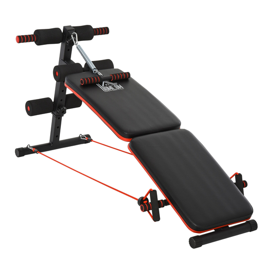
- Page 1 IN231000273V01_UK_FR_ES_DE_IT A91-085 SIT UP BENCH *The maximum user weight is 110 Kg (242lbs). IMPORTANT, RETAIN FOR FUTURE REFERENCE: READ CAREFULLY ASSEMBLY & INSTRUCTION MANUAL...
-
Page 3: Exploded-View Assembly Drawing
EXPLODED-VIEW ASSEMBLY DRAWING One Hook Foam Unit Foam Front Hook Foot Foam Pull Handle Main Frame Assembly Front Leg Tube Rear Armrest Components Drawstring Main Frame Assembly... - Page 4 PARTS 1.Main frame assembly 1PCS 2.Front support tube 1PCS 3.Front leg tube 1PCS 4.One hook foam unit 1PCS 7.Rear armrest components 5.Front hook foot foam 1PCS 6.Pull handle 1PCS 8. Extension spring 1PCS 2PCS 9. Plum blossom knob nut 10.Drawstring 2PCS 11.
-
Page 5: Installation Steps
INSTALLATION STEPS Picture A A PICTURE COMPONENTS STEP 1 Take out the front support tube assembly (2), the front leg tube assembly (3), the outer hexagon bolt M10 * 55 (14) 1 piece the Torx knob nut M10 (9) 1 piece, the hook foot foam component (4) 1 Pieces, front hook foot foam assembly (5) 1 piece. As shown in Figure A, align the corresponding holes to install and tighten the related screws. - Page 6 Picture B B PICTURE COMPONENTS STEP 2 Ia. Take out the main frame assembly (1), 3 pieces of ring bolt d10 * 55 (66) (11), 1 piece of hexagon head bolt M10 * 55 (13) and hexagon nut M10 (12). Align with the components in Figure A as shown in Figure B, align and install the corresponding holes, and tighten the related screws.
- Page 7 INSTALLATION STEPS Picture C C PICTURE COMPONENTS STEP 3 Take out the rear armrest assembly (7) 2 pieces and the assembly of B as shown in Fig. C, align and install the corresponding holes, the result is the assembly of C...
- Page 8 Picture D D PICTURE COMPONENTS STEP 4 Take out the handle assembly (6), tension spring assembly (8), and pull rope assembly(10) Two pieces, as shown in Figure F align and install the corresponding holes, and the completed result is the component D. At this point, the entire product components are completed.
-
Page 10: Instructions D'assemblage
IN231000273V01_UK_FR_ES_DE_IT A91-085 anc de musculation *Le poids maximum de l'utilisateur est de 110 Kg (242lbs). IMPORTANT - CONSERVEZ CES INFORMATIONS POUR VOTRE CONSULTATION ULTÉRIEURE: LISEZ ATTENTIVEMENT INSTRUCTIONS D’ASSEMBLAGE... - Page 11 ’ ’ ’ ’ ’ ’ ’ ’ ’ ’ ZONE CIBLE...
- Page 12 ’ ’...
- Page 18 ’ ’ ’...
-
Page 19: Instrucciones De Montaje
IN231000273V01_UK_FR_ES_DE_IT *El peso máximo del usuario no puede exceder 110 Kg (242lbs). IMPORTANTE - CONSERVE ESTA INFORMACIÓN PARA SU CONSULTA POSTERIOR: LEER DET ALLA DAMENTE INSTRUCCIONES DE MONTAJE... - Page 20 Zona objetivo...
- Page 28 IN231000273V01_UK_FR_ES_DE_IT *Das maximale Benutzergewicht beträgt 110 Kg (242lbs). WICHTIG - BITTE HEBEN SIE DIESE ANLEITUNG FÜR EINE SPÄTERE BEZUGNAHME AUF: SORGFÄLTIG DURCHLESEN GEBRAUCHSANWEISUNG...
- Page 29 ZIELZONE...
- Page 37 IN231000273V01_UK_FR_ES_DE_IT A91-085 *Il peso massimo dell'utente è di 110 Kg (242lbs). IMPORTANTE - CONSERVARE QUESTE INFORMAZIONI PER CONSULTARLE IN SEGUITO: LEGGERE ATTENTAMENTE MANUALE D’USO...
Need help?
Do you have a question about the A91-085 and is the answer not in the manual?
Questions and answers