Advertisement
Available languages
Available languages
Quick Links
IN230600321V01_IT
A91-054V01
IT
Per vedere il video di assemblaggio, scansionare il codice QR.
Le specifiche di questo prodotto possono variare rispetto alla figura,
e sono soggette a modifiche senza preavviso.
IMPORTANTE - CONSERVARE QUESTE INFORMAZIONI
PER CONSULTARLE IN SEGUITO: LEGGERE ATTENTAMENTE
ISTRUZIONI DI ASSEMBLAGGIO
Advertisement

Subscribe to Our Youtube Channel
Related Manuals for HOMCOM A91-054V01


Summary of Contents for HOMCOM A91-054V01
- Page 1 IN230600321V01_IT A91-054V01 Per vedere il video di assemblaggio, scansionare il codice QR. Le specifiche di questo prodotto possono variare rispetto alla figura, e sono soggette a modifiche senza preavviso. IMPORTANTE - CONSERVARE QUESTE INFORMAZIONI PER CONSULTARLE IN SEGUITO: LEGGERE ATTENTAMENTE...
- Page 2 AVVISO ! · Leggere e conservare questo manuale d'istruzione per un uso futuro. · Si prega di non superare i limiti di peso consentiti da questo articolo. · Peso massimo per gli utenti: 330 libbre/150 kg. · Non salire né utilizzare alcuna parte di questo prodotto come scala a pioli. ·...
- Page 5 ASSEMBLAGGIO DEL PRODOTTO Step1: Fissare le gambe laterali E separatamente nei telai laterali F con quattro Bullo- ni a testa tonda parte 2, quattro Rondelle parte 11 e quattro Dadi parte 9. Inserire i due telai laterali superiori G e fissarli con due Manopole parte 3. ATTENZIONE ALLA DIREZIONE DELLA PARTE F!
- Page 6 Step2: Fissare la parte J supporto quadrato in quattro Bullone parte 1, quattro Ron- delle parte 11 e quattro Dadi parte 9. Inserire la Barra di controllo dell'angolazione parte H. Step3: Fissare i due bracci a L con due rulli in spugna U 17*73*130 mm, ai supporti del braccio K con due Viti parte 5, due Rondelle parte 12 e due Morsetti parte 16.
- Page 7 Step4: Fissare i supporti dei braccioli ai telai laterali con due Bulloni esagonali parte 15 e due Dadi parte 9. Step5: Fissare il telaio principale della parte D al cuscino del sedile della parte C con quattro viti parte 8.
- Page 8 Step6: Fissare il Supporto anteriore parte P alla Gamba laterale parte E con due Bulloni a esta tonda parte 2, due Rondelle parte 11 e due Dadi parte 9. Fissare il telaio principale ai telai laterali con un Bullone parte 4, una Rondella parte 12 e un Dado parte 13.
- Page 9 Step7: Fissare il Supporto fisso parte N al Telaio principale e al Supporto anteriore con due Viti parte 5. Inserire il Supporto rotondo Φ22 parte S con due Rulli in spugna 17*73*130 mm parti Inserire un Supporto circolare parte T Φ19 con due Rulli in spugna 13*70*125 mm parti V.
- Page 10 Step8: Fissare la Maniglia parte M al Telaio della gamba parte R con un Bullone parte 6, un Dado parte 9 e un Morsetto parte 16. Inserire due Supporti circolari Φ19 parte T con quattro Rulli in spugna 13*70*125 mm parte V.
- Page 11 Step10: Fissare i due Telai dello schienale parti W al Cuscinetto dello schienale parte A con quattro Bulloni parte 10. Step11: Fissare il Supporto del gomito parte Q al Cuscinetto del gomito parte B con due Viti parte 5. -11-...
- Page 12 Step12: Fissare lo Schienale al Telaio principale con un Bullone esagonale parte 14 e un Dado parte 9. Inserire il Supporto gomito e fissarlo con una Manopola parte 3. -12-...
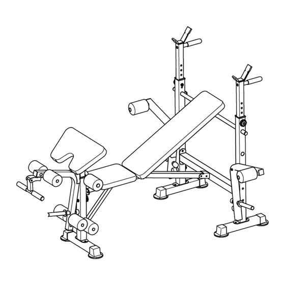
- Page 13 CARATTERISTICHE Sollevare la panca lunga per trasformare il prodotto in una panca inclinata e fissarla con la Barra di regolazione dell’angolazione parte H. -13-...
- Page 14 IN230600321V01_EN A91-054V01 The Specifications of this product may vary from this photo, subject to change with our notice IMPORTANT, RETAIN FOR FUTURE REFERENCE: READ CAREFULLY ASSEMBLY & INSTRUCTION MANUAL...
- Page 15 NOTICE ! · Please retain these instructions for future reference. · Please do not exceed the weight limitations of this item. · Maximum Weight for users: 330lbs / 150kgs. · Do not stand on or use any part of this item as a step ladder. ·...
-
Page 18: Product Assembly
PRODUCT ASSEMBLY Step1: Attach two part E side legs to two part F side frames with four part 2 carriage bolts, four part 11 washers, and four part 9 nuts. Insert two part G upper side frames and secure them with two part 3 knobs. - Page 19 Step2: Attach part J square support to the side frames with four part 1 bolts, four part 11 washers, and four part 9 nuts. Insert part H angle control rod. Step3: Attach two part L arms with two part U 17*73*130mm foam rollers, to two part K arm supports with two part 5 screws, two part 12 washers and two part 16 clamps.
- Page 20 Step4: Attach the arm supports to the side frames with two part 15 hex bolts and two part 9 nuts. Step5: Attach part D main frame to part C seat pad with four part 8 screws.
- Page 21 Step6: Attach part P front support to a part E side leg with two part 2 carriage bolts, two part 11 washers and two part 9 nuts. Attach the main frame to the side frames with a part 4 bolt, part 12 washer and part 13 nut.
- Page 22 Step7: Attach part N fixed support to the main frame and front support with two part 5 screws. Insert part S Φ22 round support with two part U 17*73*130mm foam rollers. Insert a part T Φ19 round support with two part V 13*70*125mm foam rollers. SECURE THIS PART AFTER ASSEMBLING PART N !
- Page 23 Step8: Attach part M handle to part R leg frame with a part 6 bolt, part 9 nut and part 16 clamp. Insert two part T Φ19 round supports with four part V 13*70*125mm foam rollers. Step9: Attach the leg frame to the front support with a part 6 bolt and part 9 nut.
- Page 24 Step10: Attach two part W backrest frames to part A backrest pad with four part 10 bolts. Step11: Attach part Q elbow support to part B elbow pad with two part 5 screws.
- Page 25 Step12: Attach the backrest to the main frame with a part 14 hex bolt and part 9 nut. Insert the elbow pad and secure it with a part 3 knob.
- Page 26 FEATURES Flip up the long bench to transform into an incline bench and secure with part H angle control rod.
Need help?
Do you have a question about the A91-054V01 and is the answer not in the manual?
Questions and answers