Advertisement
Quick Links
Advertisement

Subscribe to Our Youtube Channel
Related Manuals for HOMCOM A91-085


Summary of Contents for HOMCOM A91-085
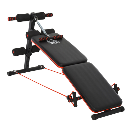
- Page 1 SIT UP BENCH A91-085 EN C000000...
-
Page 2: Exercise Instructions
EXERCISE INSTRUCTIONS Using your bike provides you with several bene ts, it will improve your physical tness, tone muscle and in conjunction with calorie controlled diet help you l ose weight. 1.The Warm Up Phase This stage helps get the blood owing around the b ody and the muscles working properly. -
Page 3: Exploded-View Assembly Drawing
EXPLODED-VIEW ASSEMBLY DRAWING One Hook Foam Unit Foam Front Hook Foot Foam Pull Handle Main Frame Assembly Front Leg Tube Rear Armrest Components Drawstring Main Frame Assembly... - Page 4 PARTS 1.Main frame assembly 1PCS 2.Front support tube 1PCS 3.Front leg tube 1PCS 4.One hook foam unit 1PCS 7.Rear armrest components 5.Front hook foot foam 1PCS 6.Pull handle 1PCS 8. Extension spring 1PCS 2PCS 9. Plum blossom knob nut 10.Drawstring 2PCS 11.
-
Page 5: Installation Steps
INSTALLATION STEPS Picture A A PICTURE COMPONENTS STEP 1 Take out the front support tube assembly (2), the front leg tube assembly (3), the outer hexagon bolt M10 * 55 (14) 1 piece the Torx knob nut M10 (9) 1 piece, the hook foot foam component (4) 1 Pieces, front hook foot foam assembly (5) 1 piece. As shown in Figure A, align the corresponding holes to install and tighten the related screws. - Page 6 Picture B B PICTURE COMPONENTS STEP 2 Ia. Take out the main frame assembly (1), 3 pieces of ring bolt d10 * 55 (66) (11), 1 piece of hexagon head bolt M10 * 55 (13) and hexagon nut M10 (12). Align with the components in Figure A as shown in Figure B, align and install the corresponding holes, and tighten the related screws.
- Page 7 INSTALLATION STEPS Picture C C PICTURE COMPONENTS STEP 3 Take out the rear armrest assembly (7) 2 pieces and the assembly of B as shown in Fig. C, align and install the corresponding holes, the result is the assembly of C...
- Page 8 Picture D D PICTURE COMPONENTS STEP 4 Take out the handle assembly (6), tension spring assembly (8), and pull rope assembly(10) Two pieces, as shown in Figure F align and install the corresponding holes, and the completed result is the component D. At this point, the entire product components are completed.
- Page 9 0044-800-240-4004 enquiries@mhstar.co.uk...
Need help?
Do you have a question about the A91-085 and is the answer not in the manual?
Questions and answers