
Related Manuals for HOMCOM A91-054V01


Summary of Contents for HOMCOM A91-054V01
- Page 1 INamc003V01_ES A91-054V01 IMPORTANT, RETAIN FOR FUTURE REFERENCE: READ CAREFULLY ASSEMBLY & INSTRUCTION MANUAL...
- Page 2 ¡NOTAS! ·Por favor conserve estas instrucciones para futuras referencias. ·Por favor, no exceda las limitaciones de peso de este producto. ·Peso máximo de los usuarios: 330lbs / 150kgs. ·No se suba al producto, ni utilice ninguna parte de este producto como escalera de mano.
- Page 3 HARDWARE 4. PERNO M8x55mm 1. PERNO M10x65mm 3. POMOS M10x55mm 1 PIEZA 2. PERNOS DE MARCO 4 PIEZAS 3 PIEZAS M10x65mm 6PIEZAS TORNILLO 6. PERNO M10x55mm TORNILLO TORNILLO M8x20mm 6PIEZAS 2 PIEZAS M8x16mm 2 PIEZAS M6x16mm 4 PIEZAS 9. TUERCA M10 10.
- Page 4 PIEZAS COJÍN B. COJÍN DE CODO COJÍN RESPALDO 1PIEZA D. MARCO 1PIEZA ASIENTO 1PIEZA PRINCIPAL 1PIEZA H.VARILLA CONTROL ÁNGULO 1PIEZA PATA LATERAL G. MARCO LATERAL F. MARCO LATERAL 3PIEZAS SUPERIOR 2PIEZAS 2PIEZAS J.SOPORTE L. BRAZO 2PIEZAS M. MANIJA 1PIEZA K. SOPORTE CUADRADO 1PIEZA BRAZO 2PIEZAS SOPORTE...
-
Page 5: Montaje Del Producto
MONTAJE DEL PRODUCTO Paso 1: Fije las dos patas laterales E a los dos marcos laterales F con cuatro pernos de marco 2, cuatro arandelas 11 y cuatro tuercas 9. Inserte los dos marcos laterales superiores G y fíjelos con dos pomos 3. ¡... - Page 6 Paso 2: Fije el soporte cuadrado J a los marcos laterales con cuatro pernos 1, cuatro arandelas 11 y cuatro tuercas 9. Inserte la varilla de control angular de la pieza H. Paso 3: Fije los dos brazos L con dos rodillos de espuma U de 17*73*130mm, a dos soportes del brazo K con dos tornillos 5, dos arandelas 12 y dos abrazaderas ¡OBSÉRVESE LA DIRECCIÓN DE LA PIEZA K !
- Page 7 Paso 4: Fije los soportes de los brazos a los marcos laterales con dos tornillos hexagonales 15 y dos tuercas 9. Paso 5: Fije la pieza D de la estructura principal a la pieza C del cojín del asiento con cuatro tornillos 8.
- Page 8 Paso 6: Fije el soporte frontal P a una pata lateral E con dos tornillos de marco 2, dos arandelas 11 y dos tuercas 9. Fije el marco principal a los marcos laterales con un tornillo 4, una arandela 12 y una tuerca 13.
- Page 9 Paso7: Fije el soporte fijo N al marco principal y al soporte frontal con dos tornillos 5. Inserte el soporte redondo de Φ22 S con dos rodillos de espuma U de 17*73*130mm. Inserte el soporte redondo de Φ19 T con dos rodillos de espuma de13*70*125mm V.
- Page 10 Paso 8: Fije el mango M al marco de pata R con un perno 6, una tuerca 9 y una abrazadera 16. Inserte dos soportes redondos de Φ19 T con cuatro rodillos de espuma de 13*70*125mm V. Paso 9: Fije el marco de las patas al soporte delantero con un tornillo 6 y una tuerca 9.
- Page 11 Paso 10: Fije los dos marcos del respaldo W al cojín del respaldo A con cuatro tornillos 10. Paso 11: Fije el soporte del codo Q al codo B con dos tornillos 5. -11-...
- Page 12 Paso 12: Fije el respaldo al marco principal con un tornillo hexagonal 14 y una tuerca 9. Inserte el codo y fíjelo con un pomo 3. -12-...
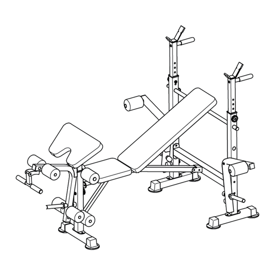
- Page 13 CARACTERÍSTICAS Voltee el banco largo para transformarlo en un banco inclinado y asegúrelo con la varilla de control angular H. -13-...
- Page 14 The Specifications of this product may vary from this photo, subject to change with our notice -14-...
- Page 15 NOTICE ! · Please retain these instructions for future reference. · Please do not exceed the weight limitations of this item. · Maximum Weight for users: 330lbs / 150kgs. · Do not stand on or use any part of this item as a step ladder. ·...
- Page 16 -16-...
- Page 17 -17-...
-
Page 18: Product Assembly
PRODUCT ASSEMBLY Step1: Attach two part E side legs to two part F side frames with four part 2 carriage bolts, four part 11 washers, and four part 9 nuts. Insert two part G upper side frames and secure them with two part 3 knobs. -18-... - Page 19 Step2: Attach part J square support to the side frames with four part 1 bolts, four part 11 washers, and four part 9 nuts. Insert part H angle control rod. Step3: Attach two part L arms with two part U 17*73*130mm foam rollers, to two part K arm supports with two part 5 screws, two part 12 washers and two part 16 clamps.
- Page 20 Step4: Attach the arm supports to the side frames with two part 15 hex bolts and two part 9 nuts. Step5: Attach part D main frame to part C seat pad with four part 8 screws. -20-...
- Page 21 Step6: Attach part P front support to a part E side leg with two part 2 carriage bolts, two part 11 washers and two part 9 nuts. Attach the main frame to the side frames with a part 4 bolt, part 12 washer and part 13 nut.
- Page 22 Step7: Attach part N fixed support to the main frame and front support with two part 5 screws. Insert part S Φ22 round support with two part U 17*73*130mm foam rollers. Insert a part T Φ19 round support with two part V 13*70*125mm foam rollers. SECURE THIS PART AFTER ASSEMBLING PART N ! -22-...
- Page 23 Step8: Attach part M handle to part R leg frame with a part 6 bolt, part 9 nut and part 16 clamp. Insert two part T Φ19 round supports with four part V 13*70*125mm foam rollers. Step9: Attach the leg frame to the front support with a part 6 bolt and part 9 nut. -23-...
- Page 24 Step10: Attach two part W backrest frames to part A backrest pad with four part 10 bolts. Step11: Attach part Q elbow support to part B elbow pad with two part 5 screws. -24-...
- Page 25 Step12: Attach the backrest to the main frame with a part 14 hex bolt and part 9 nut. Insert the elbow pad and secure it with a part 3 knob. -25-...
- Page 26 FEATURES Flip up the long bench to transform into an incline bench and secure with part H angle control rod. -26-...
-
Page 27: Manual De Instruções
INamc003V01_PT A91-054V01 Vídeo de montagem por favor scaneie o código QR As especificações deste produto podem variar desta foto, sujeitas a alterações com o nosso aviso IMPORTANTE, RETER PARA REFERÊNCIA FUTURA: LEIA ATENTAMENTE MANUAL DE INSTRUÇÕES... - Page 28 NOTAS! -Por favor, retenha estas instruções para referência futura. -Por favor, não exceder as limitações de peso deste produto. -Peso máximo do utilizador: 330lbs / 150kgs. -Não subir sobre o produto, nem utilizar qualquer parte deste produto como escada de mão. -Aperte bem todos os parafusos, porcas e puxadores antes de utilizar o produto.
- Page 29 FERRAGENS 2. PARAFUSO DA 1. PARAFUSO 3. MAÇANETAS 4. PARAFUSO ESTRUTURA M10x65mm M10x55mm M8x55mm 1 PEÇA 4 PEÇAS M10x65mm 6PEÇAS 3 PEÇAS 5. PARAFUSOS 6. PARAFUSOS 7. PARAFUSOS 8. PARAFUSOS M8x20mm 6PEÇAS M10x55mm 2 M8x16mm 2 PEÇAS M6x16mm 4 PEÇAS PEÇAS 9.
- Page 30 PEÇAS C.ALMOFADA DO D. ESTRUTURA ASSENTO 1PEÇA A. ALMOFADA PRINCIPAL 1PEÇA B. ALMOFADA DO ENCOSTO DO COTOVELO 1PEÇA 1PEÇA H. HASTE DE G. ESTRUTURA E.PÉ LATERAL CONTROLO DE F. ESTRUTURA LATERAL 3PEÇA ÂNGULO 1 PEÇA LATERAL 2 PEÇAS SUPERIOR 2PEÇAS J.SUPORTE L.
- Page 31 MONTAGEM DO PRODUTO Passo 1: Fixar as dois pés laterais (E) e às duas estruturas laterais (F) com quatro parafusos de estrutura (2), quatro arruelas (11) e quatro porcas (9). OBSERVE A DIREÇÃO DA PEÇA F...
- Page 32 Passo 2:Inserir as duas estruturas laterais superiores (G) e prendê-las com duas maçanetas (3). Passo 3: Fixar o suporte quadrado (J) às estruturas laterais (F) com quatro parafusos (1), quatro arruelas (11) e quatro porcas (9). Inserir a haste de controlo de ângulo (H).
- Page 33 Passo 4: Fixar os suportes dos braços às estruturas laterais com dois parafusos hexagonais (15) e duas porcas (9). Passo 5: Fixar a parte D da estrutura principal à parte C da almofada do assento com quatro parafusos (8).
- Page 34 Passo 6: Fixar o suporte dianteiro (P) a uma perna lateral (E) com dois parafusos de estrutura (2), duas anilhas (11) e duas porcas (9). Fixar a estrutura principal às estruturas laterais com um parafuso (4), uma arruela (12) e uma porca (13). Inserir o pino (17). Fixar o suporte frontal à...
- Page 35 Passo 7: Fixar o suporte fixo (N) à estrutura principal e ao suporte frontal com dois parafusos (5). Inserir o suporte redondo Φ22 (S) com dois rolos de espuma de 17*73*130mm (U). Inserir o suporte redondo Φ19 (T) com dois rolos de espuma 13*70*70*125mm (V).
- Page 36 Passo 8: Fixar o punho (M) à estrutura do pé (R) com parafuso (6), porca (9) e braçadeira (16). Inserir dois suportes redondos Φ19 (T) com quatro rolos de espuma de 13*70*125mm (V). Passo 9: Fixar a estrutura dos pés ao suporte frontal com parafuso (6) e porca (9).
- Page 37 Passo 10: Fixar as duas estruturas de encosto (W) à almofada de encosto (A) com quatro parafusos (10). Passo 11: Fixar o suporte do cotovelo (Q) a almofada do cotovelo (B) com dois parafusos (5). -11-...
- Page 38 Passo 12: Fixar o encosto à estrutura principal com um parafuso hexagonal (14) e uma porca (9). Inserir o cotovelo e prendê-lo com uma maçaneta (3). -12-...
- Page 39 CARACTERÍSTICAS Transforme o banco longo num banco inclinado e fixe-o com a haste de controlo de ângulo H. -13-...
- Page 40 The Specifications of this product may vary from this photo, subject to change with our notice -14-...
- Page 41 NOTICE ! · Please retain these instructions for future reference. · Please do not exceed the weight limitations of this item. · Maximum Weight for users: 330lbs / 150kgs. · Do not stand on or use any part of this item as a step ladder. ·...
- Page 42 -16-...
- Page 43 -17-...
- Page 44 PRODUCT ASSEMBLY Step1: Attach two part E side legs to two part F side frames with four part 2 carriage bolts, four part 11 washers, and four part 9 nuts. Insert two part G upper side frames and secure them with two part 3 knobs. -18-...
- Page 45 Step2: Attach part J square support to the side frames with four part 1 bolts, four part 11 washers, and four part 9 nuts. Insert part H angle control rod. Step3: Attach two part L arms with two part U 17*73*130mm foam rollers, to two part K arm supports with two part 5 screws, two part 12 washers and two part 16 clamps.
- Page 46 Step4: Attach the arm supports to the side frames with two part 15 hex bolts and two part 9 nuts. Step5: Attach part D main frame to part C seat pad with four part 8 screws. -20-...
- Page 47 Step6: Attach part P front support to a part E side leg with two part 2 carriage bolts, two part 11 washers and two part 9 nuts. Attach the main frame to the side frames with a part 4 bolt, part 12 washer and part 13 nut.
- Page 48 Step7: Attach part N fixed support to the main frame and front support with two part 5 screws. Insert part S Φ22 round support with two part U 17*73*130mm foam rollers. Insert a part T Φ19 round support with two part V 13*70*125mm foam rollers. SECURE THIS PART AFTER ASSEMBLING PART N ! -22-...
- Page 49 Step8: Attach part M handle to part R leg frame with a part 6 bolt, part 9 nut and part 16 clamp. Insert two part T Φ19 round supports with four part V 13*70*125mm foam rollers. Step9: Attach the leg frame to the front support with a part 6 bolt and part 9 nut. -23-...
- Page 50 Step10: Attach two part W backrest frames to part A backrest pad with four part 10 bolts. Step11: Attach part Q elbow support to part B elbow pad with two part 5 screws. -24-...
- Page 51 Step12: Attach the backrest to the main frame with a part 14 hex bolt and part 9 nut. Insert the elbow pad and secure it with a part 3 knob. -25-...
- Page 52 FEATURES Flip up the long bench to transform into an incline bench and secure with part H angle control rod. -26-...
- Page 53 Si tiene alguna pregunta, comuníquese con nuestro Centro de Atención al Cliente. Nuestros datos de contacto son los siguientes: 0034-931294512 atencioncliente@aosom.es IMPORTADOR: SPANISH AOSOM, S.L. C/ ROC GROS, Nº 15. 08550, ELS HOSTALETS DE BALENYÀ, SPAIN. B66295775 WWW.AOSOM.ES ATENCIONCLIENTE@AOSOM.ES TEL: 931294512 HECHO EN CHINA Se tiver alguma dúvida, por favor contacte o nosso Centro de Atendimento ao Cliente.
Need help?
Do you have a question about the A91-054V01 and is the answer not in the manual?
Questions and answers