Table of Contents
Advertisement
Quick Links
Operating Guide
Termix VX with complete insulation
1.0 Table of Contents
1.0 Table of Contents ............................................. 1
2.0 Functional description...................................... 2
3.0 Safety notes..................................................... 3
3.1
Safety Notes - general . . . . . . . . . . . . . . . . . . . . . . . . . . . . . . . . . . . . . . . . . . . . 3
4.0 Mounting ........................................................ 4
4.1
Mounting . . . . . . . . . . . . . . . . . . . . . . . . . . . . . . . . . . . . . . . . . . . . . . . . . . . . . . . . . . . 4
4.2
Start-up. . . . . . . . . . . . . . . . . . . . . . . . . . . . . . . . . . . . . . . . . . . . . . . . . . . . . . . . . . . . . . 7
4.3
Electrical connections. . . . . . . . . . . . . . . . . . . . . . . . . . . . . . . . . . . . . . . . . . . . . 9
5.0 Design............................................................. 10
5.1
Design . . . . . . . . . . . . . . . . . . . . . . . . . . . . . . . . . . . . . . . . . . . . . . . . . . . . . . . . . . . . . . . 10
5.2
Schematic diagram . . . . . . . . . . . . . . . . . . . . . . . . . . . . . . . . . . . . . . . . . . . . . . . . 11
6.0 Controls .......................................................... 12
6.1
Heating circuit. . . . . . . . . . . . . . . . . . . . . . . . . . . . . . . . . . . . . . . . . . . . . . . . . . . . . . 12
6.2
Other. . . . . . . . . . . . . . . . . . . . . . . . . . . . . . . . . . . . . . . . . . . . . . . . . . . . . . . . . . . . . . . . . 16
6.3
Maintenance. . . . . . . . . . . . . . . . . . . . . . . . . . . . . . . . . . . . . . . . . . . . . . . . . . . . . . . . 18
7.0 Troubleshooting .............................................. 19
7.1
Troubleshooting in general . . . . . . . . . . . . . . . . . . . . . . . . . . . . . . . . . . . . . . 19
7.2
Troubleshooting HE . . . . . . . . . . . . . . . . . . . . . . . . . . . . . . . . . . . . . . . . . . . . . . . 20
7.3
Disposal . . . . . . . . . . . . . . . . . . . . . . . . . . . . . . . . . . . . . . . . . . . . . . . . . . . . . . . . . . . . . 22
© Danfoss | 2022.11
8.0 Declaration...................................................... 23
8.1
Declaration of conformity . . . . . . . . . . . . . . . . . . . . . . . . . . . . . . . . . . . . . . . . 23
AQ221686472754en-010401 / LUK4030601 | 1
Advertisement
Table of Contents
Troubleshooting

Subscribe to Our Youtube Channel
Related Manuals for Danfoss Termix VX


Summary of Contents for Danfoss Termix VX
-
Page 1: Table Of Contents
Operating Guide Termix VX with complete insulation 1.0 Table of Contents 1.0 Table of Contents ..........1 8.0 Declaration............23 Declaration of conformity ........23 2.0 Functional description........ -
Page 2: Functional Description
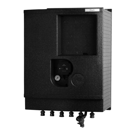
District heating substation for indirect heating. Designed for wall-mounting. Application The Termix VX is a complete solution for space heating with optimal safety, efficient energy transfer, service-friendly construction and a compact design. The substation is used if a heat exchanger is required or on a conversion to district heating where the existing equipment is unsuitable for direct connection. -
Page 3: Safety Notes
REACH All Danfoss A/S products fulfill the requirements in REACH. One of the obligations in REACH is to inform customers about presence of Candidate list substances if any, we hereby inform... -
Page 4: Mounting
Assembly, start-up and maintenance work must be performed by primary supply to Danfoss substations. For the sake of simplicity, qualified and authorized personnel only. DH can be taken to mean the primary supply. - Page 5 Operating Guide Termix VX with complete insulation 4.1.1 Installation Mounting: Adequate space Please allow adequate space around the substation for mounting and maintenance purposes. Orientation The station must be mounted so that components, keyholes and labels are placed correctly. If you wish to mount the station differently please contact your supplier.
- Page 6 Operating Guide Termix VX with complete insulation Keep the ECL controller in its position while removing the insulation front completely by pulling at the lower end of the insulation front. 4.1.3 Mounting the display of the energy meter Mark the position of the fixation points of the bracket for the energy display and screw the two plugs supplied into the insulation front.
-
Page 7: Start-Up
Operating Guide Termix VX with complete insulation 4.2 Start-up Start-up, Indirect heating Filling: Re-tighten connections 1: First fill After water has been added to the system and the system has been When carrying out first fill, the heat exchanger must be slowly filled put into operation, re-tighten ALL ALL connections. - Page 8 Operating Guide Termix VX with complete insulation Under floor heating: Pump stop function If the substation is used in connection with under floor heating, the circulation pump must be connected to the pump stop function in the under floor heating controller. The pump must be stopped if all under floor heating circuits are closed.
-
Page 9: Electrical Connections
Operating Guide Termix VX with complete insulation 4.3 Electrical connections Before making electrical connections, please note the following: Safety notes Authorized electrician Please read the relevant parts of the safety notes. Electrical connections must be made by an authorized electrician only. -
Page 10: Design
Operating Guide Termix VX with complete insulation 5.0 Design 5.1 Design Your substation might look different than the substation shown. Design description A Heat exchanger, HE 10 Circulator pump 38 Expansion tank 14 Sensor pocket, energy meter 41 Fitting piece, energy meter... -
Page 11: Schematic Diagram
Operating Guide Termix VX with complete insulation 5.2 Schematic diagram Supply Supply Return Return Your substation might look different than the schematic diagram shown. Schematic description A Heat exchanger, HE 10 Circulator pump 26 Pressure gauge 14 Sensor pocket, energy meter... -
Page 12: Controls
Operating Guide Termix VX with complete insulation 6.0 Controls 6.1 Heating circuit 6.1.1 Differential pressure controller The differential pressure controller smooths out the fluctuations in pressure arriving from the district heating network. The operating pressure in the substation is thus held steady. - Page 13 Operating Guide Termix VX with complete insulation 6.1.4 Electronic control Substations with electronic control must be set in accordance with manufacturer´s instructions. Where the room temperature is controlled by radiator thermostats, it is recommended that thermostats be set for minimum temperature in each room.
- Page 14 Operating Guide Termix VX with complete insulation 6.1.7 Grundfos UPM3 AUTO instructions Control mode Each push on the button switches to the next program setting. The choice of operation mode depends on the type of heating system and the pressure loss in the system.
- Page 15 Operating Guide Termix VX with complete insulation 6.1.8 HE pressure gauge The HE pressure gauge indicates the pressure of the HE system. AQ221686472754en–010401 / LUK4030601 © Danfoss | 2022.11 | 15...
-
Page 16: Other
Operating Guide Termix VX with complete insulation 6.2 Other 6.2.1 Safety valve The purpose of the safety valve is to protect the substation from excessive pressure. The blow-off pipe from the safety valve must not be closed. The blow-off pipe outlet should be placed so that it discharges freely and it is possible to observe any dripping from the safety valve. - Page 17 Operating Guide Termix VX with complete insulation 6.2.3 Fitting piece The substation is equipped with a fitting piece for energy meter. Assembly of energy meters: 1: Close ball valves Close the ball valves on DH Supply and DH Return, if there is water on the system.
-
Page 18: Maintenance
Venting Checking that the system is thoroughly vented. Inspections should be carried out minimum every two years. Spare parts can be ordered from Danfoss. Please ensure that any enquiry includes the substation serial number. AQ221686472754en–010401 / LUK4030601 18 | © Danfoss | 2022.11... -
Page 19: Troubleshooting
Operating Guide Termix VX with complete insulation 7.0 Troubleshooting 7.1 Troubleshooting in general In the event of operating disturbances, the following basic features should be checked before carrying out actual troubleshooting: • the substation is connected to electricity, Authorized personnel only •... -
Page 20: Troubleshooting He
Operating Guide Termix VX with complete insulation 7.2 Troubleshooting HE Problem Possible cause Solution Too little or no heat. Strainer clogged in DH or HE circuit Clean gate/strainer(s). (radiator circuit). The filter in the energy meter on DH circuit Clean the filter (after consulting the DH clogged. - Page 21 Operating Guide Termix VX with complete insulation Too high DH return temperature. Too small heating surface/too small Increase total heating surface. radiators compared to the total heating requirement of the building. Poor utilization of existing heating surface. Make sure the heat is distributed evenly Defective sensor on self-acting thermostat.
-
Page 22: Disposal
Operating Guide Termix VX with complete insulation 7.3 Disposal Disposal note This symbol on the product indicates that it may not be disposed of as household waste.. It must be handed over to the applicable take-back scheme for the recycling of electrical and electronic equipment. -
Page 23: Declaration
Operating Guide Termix VX with complete insulation 8.0 Declaration 8.1 Declaration of conformity AQ221686472754en–010401 / LUK4030601 © Danfoss | 2022.11 | 23... - Page 24 Operating Guide Termix VX with complete insulation AQ221686472754en–010401 / LUK4030601 24| © Danfoss | 2022.11...
Need help?
Do you have a question about the Termix VX and is the answer not in the manual?
Questions and answers