Advertisement
Quick Links
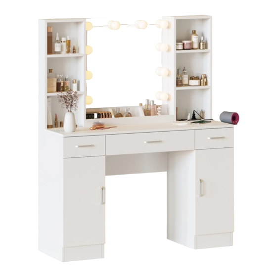
D8L239BS02
WhatsApp community↑
D8L239HS02
D8L239BR02
As this item contains many parts, please read the installation
instruction carefully before installation . Please use tools
properly and carefully. If you have any questions about the
product and installation, please contact us.
service@vabchesofficial.com
Our professional after-sales team will serve you online all
day.
1-42
Advertisement

Subscribe to Our Youtube Channel
Related Manuals for VABCHES D8L239BS02


Summary of Contents for VABCHES D8L239BS02
- Page 1 D8L239BS02 WhatsApp community↑ D8L239HS02 D8L239BR02 As this item contains many parts, please read the installation instruction carefully before installation . Please use tools properly and carefully. If you have any questions about the product and installation, please contact us. service@vabchesofficial.com Our professional after-sales team will serve you online all day.
-
Page 2: Before You Start
Before You Start Read through each step carefully and follow the proper order Separate and count all your parts and hardware Give yourself enough room for the assembly process Have the following tools: Flat Head Screwdriver, #2 Phillips Head Screwdriver and Hammer Caution: If using a power drill or power screwdriver for screwing, please be aware of to slow down and stop when screw is tight. -
Page 3: Board Identification
Board Identification Not actual size DRESSING MIRROR UPPER LEFT SIDE PANEL UPPER LEFT PARTITION Qty:1 Qty:1 Qty:1 UPPER RIGHT PARTITION UPPER RIGHT SIDE PANEL FIXED SHELF Qty:1 Qty:1 Qty:6 FRONT BAFFLE SMALL PARTITION DESK TOP Qty:1 Qty:2 Qty:1 3-42... -
Page 4: Adjustable Shelf
Board Identification Not actual size BACK PANEL LOWER LEFT SIDE PANEL LOWER LEFT PARTITION Qty:3 Qty:1 Qty:1 LOWER RIGHT PARTITION LOWER RIGHT SIDE PANEL SIDE SLAT UNDER DRAWER Qty:1 Qty:1 Qty:2 ADJUSTABLE SHELF BOTTOM BOTTOM FRONT RAIL Qty:2 Qty:2 Qty:2 4-42... - Page 5 Board Identification Not actual size LEFT DOOR RIGHT DOOR MIDDLE SLAT UNDER DRAWER Qty:1 Qty:1 Qty:1 LOWER MIDDLE BACK DRAWER FRONT DRAWER LEFT SIDE Qty:1 Qty:2 Qty:1 DRAWER RIGHT SIDE SMALL DRAWER BACK SMALL DRAWER BOTTOM Qty:1 Qty:2 Qty:2 5-42...
- Page 6 Board Identification BIG DRAWER FRONT BIG DRAWER BACK BIG DRAWER BOTTOM Qty:1 Qty:1 Qty:1 STOOL SIDE PANEL STOOL FRONT APRON STOOL BACK APRON Qty:2 Qty:1 Qty:1 STOOL BOTTOM BOARD SPONGE CUSHION BACK PANEL Qty:1 Qty:1 Qty:1 6-42...
- Page 7 Board Identification DRAWER LEFT SIDE DRAWER RIGHT SIDE Qty:2 Qty:2 7-42...
- Page 8 Board Identification Not actual size 8-42...
-
Page 9: Part List
Part List Ø15X9.5mm Ø6.5X35mm Ø8X30mm Ø6X30mm CAM LOCK CAM BOLT WOODEN DOWEL WOODEN DOWEL spare:3 spare:3 spare:3 spare:3 Ø6.3X50mm Ø4X40mm Ø3.5X14mm Ø3X14mm SCREW SCREW SCREW SCREW spare:2 spare:3 spare:3 spare:3 M4X18mm 107X10X21mm Ø5X17mm Ø25mm SCREW HANDLE SHELF SUPPORT HINGE spare:1 spare:1 14"... - Page 10 Part List 14" 14" 350mm 350mm 15DL 15DR X1 set LEFT DRAWER RUNNER RIGHT DRAWER RUNNER LIGHT BULB TIPPING RESTRAINT HARDWARE KIT Ø4X14mm Ø3X12mm SCREW PLUG BOARD HAIR DRYER RACK SCREW spare:1 spare:1 Cam Lock Fastening System Insert the cam bolt into the hole first, then insert the cam lock and lock it.
- Page 11 STEP1 Ø15X9.5mm Ø6.5X35mm Ø4X40mm GROOVE Proper orientation of CAM LOCK 11-42...
- Page 12 STEP2 Ø4X40mm GROOVE 12-42...
- Page 13 STEP3 Ø15X9.5mm Ø6.5X35mm Proper orientation of CAM LOCK 13-42...
- Page 14 STEP4 Ø3.5X14mm 350mm 350mm 15DL 15DR 14-42...
- Page 15 STEP5 Ø3.5X14mm 350mm 350mm 15DL 15DR 15-42...
- Page 16 STEP6 Ø6.5X35mm 16-42...
- Page 17 STEP7 Ø15X9.5mm Ø6X30mm Ø21mm EDGE BANDING EDGE BANDING Proper orientation of CAM LOCK 17-42...
- Page 18 STEP8 Ø6.5X35mm 18-42...
- Page 19 STEP9 Ø15X9.5mm Ø6.5X35mm Ø6X30mm Ø4X40mm Ø21mm Proper orientation of CAM LOCK 19-42...
- Page 20 STEP10 Ø15X9.5mm Ø8X30mm Ø4X40mm Ø21mm THIS STEP REQUIRES 2 PEOPLE Proper orientation of CAM LOCK 20-42...
- Page 21 STEP11 Ø6.5X35mm Ø3X12mm FLIP OVER 21-42...
- Page 22 STEP12 Ø8X30mm Ø6X30mm Ø4X40mm Note: before installing the wood dowel, please ensure that the size of these two wood dowel pins is Ø8*30MM Ø8*30MM X2pcs Ø6* 30MM X4pcs 22-42...
- Page 23 STEP13 Ø6.3X50mm 4X65mm 23-42...
- Page 24 STEP14 14" 14" 350mm 350mm Ø3.5X14mm 15CL 15CR 15CL 15CR 24-42...
- Page 25 STEP15 14" 14" Ø6.5X35mm Ø3.5X14mm 350mm 350mm 15CR 15CL 15CR FLIP OVER 15CL 25-42...
- Page 26 STEP16 14" 14" Ø6.5X35mm Ø3.5X14mm 350mm 350mm 15CR 15CL 15CL FLIP OVER 15CR 26-42...
- Page 27 STEP17 Ø15X9.5mm Ø6.5X35mm Ø6X30mm Proper orientation of CAM LOCK 27-42...
- Page 28 STEP18 Ø6X30mm Ø4X40mm Ø21mm 28-42...
- Page 29 STEP19 Ø15X9.5mm Ø8X30mm Ø6X30mm Ø6.3X50mm THIS STEP REQUIRES 2 PEOPLE 4X65mm Ø6*30MM X2pcs Ø8*30MM X4pcs Note: before installing the wood dowel, please ensure that the size of these four wood dowel pins is Ø8*30MM Proper orientation of CAM LOCK 29-42...
- Page 30 STEP20 Ø8X30mm 30-42...
- Page 31 STEP21 Ø15X9.5mm THIS STEP REQUIRES 2 PEOPLE Proper orientation of CAM LOCK 31-42...
- Page 32 STEP22 Ø3X14mm X1 set Align the semicircular holes to form a circular hole 90° 90° 90° Before attaching the back panel, be sure that the unit is at 90°. 90° Pass the power plug through this hole . 32-42...
- Page 33 STEP23 Ø25mm Ø3.5X14mm 33-42...
- Page 34 STEP24 Ø3.5X14mm M4X18mm 107X10X21mm 34-42...
- Page 35 STEP25 To adjust the vertical height. Loosen the four screws "A" on both hinges. Two of them are usually in slotted holes which allows you to adjust up or down by a few mm. Then tighten back up. To adjust depth. Loosen screw "B"...
- Page 36 STEP26 Ø5X17mm M4X18mm 107X10X21mm Cabinet Slide Drawer Slide 36-42...
- Page 37 STEP27 Ø8X30mm Ø6.3X50mm Ø3.5X14mm Ø21mm Ø4X65mm Note: the hole faces inward 37-42...
- Page 38 STEP28 Ø4X14mm You can install the hair dryer rack(20) on the left or right according to your needs 38-42...
- Page 39 STEP29 For specific installation and debugging, please read the last two pages PEFOAM ABS lamp holder USB power adapter Switch regulator 39-42...
- Page 40 STEP30 NOTE :The tipping restraint hardware included is for wooden stud wall construction. It must be attached to a wall stud. Depending upon your wall construction different We have included a set of tipping restraint hardware for anchor hardware maybe required. Please contact your local this unit.
- Page 41 Thank you for purchasing our company s DIY makeup mirror fill Vanity Mirror Lights Light products, this product supports DIY own home mirror, instantly make their own mirror into a modern fashion makeup with LED Fill mirror.Even more interesting is that you can adjust the color temperature by yourself ! The color temperature is adjustable Product Features:...
- Page 42 Use the installation details see inside pages. Functional Description: Install reference diagram: Brightness+ PC lamp cover Output Switch button Adjust the color temperature Special feature: Brightness- Rotate the bulbs clockwise or anticlockwise, the ball bubble spacing becomes shorter, the connection input line shrinks and hides in the ball bubble bottom cover;...
Need help?
Do you have a question about the D8L239BS02 and is the answer not in the manual?
Questions and answers