Advertisement
Quick Links
WhatsApp community↑
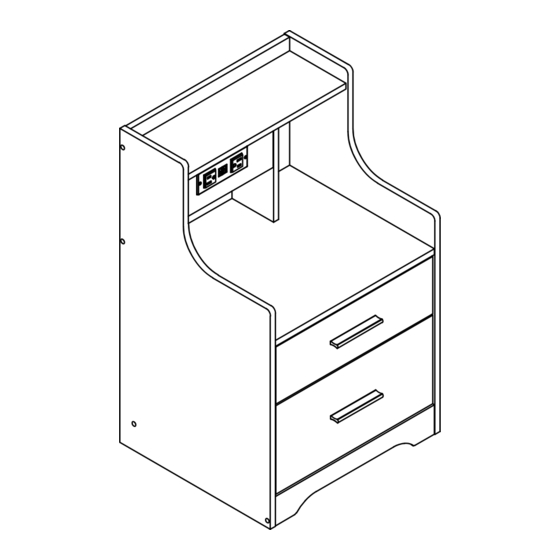
D8L232BS01
As this item contains many parts, please read the installation
instruction carefully before installation and complete the
installation with the cooperation of your partner. Please use
tools properly and carefully. If you have any questions about
the product and installation, please contact us.
service@vabchesofficial.com
Our professional after-sales team will serve you online all
day.
1/24
Advertisement

Related Manuals for VABCHES D8L232BS01


Summary of Contents for VABCHES D8L232BS01
- Page 1 WhatsApp community↑ D8L232BS01 As this item contains many parts, please read the installation instruction carefully before installation and complete the installation with the cooperation of your partner. Please use tools properly and carefully. If you have any questions about the product and installation, please contact us.
-
Page 2: Before You Start
Before You Start Read through each step carefully and follow the proper order Separate and count all your parts and hardware Give yourself enough room for the assembly process Have the following tools: Flat Head Screwdriver, #2 Phillips Head Screwdriver and Hammer Caution: If using a power drill or power screwdriver for screwing, please be aware of to slow down and stop when screw is tight. -
Page 3: Board Identification
Board Identification Not actual size LEFT SIDE PANEL RIGHT SIDE PANEL Qty:1 Qty:1 Qty:1 BACK PANEL FIXED SHELF HUTCH SIDE PANEL Qty:1 Qty:1 Qty:1 BACK PANEL BOTTOM FRONT RAIL FRONT PANEL Qty:1 Qty:1 Qty:1 3/24... -
Page 4: Drawer Bottom
Board Identification Not actual size REAR PULL BAR BIG DRAWER FRONT DRAWER LEFT SIDE Qty:1 Qty:1 Qty:1 DRAWER RIGHT SIDE DRAWER BOTTOM DRAWER BACK PANEL Qty:1 Qty:2 Qty:1 SMALL DRAWER FRONT DRAWER LEFT SIDE DRAWER RIGHT SIDE Qty:1 Qty:1 Qty:1 4/24... - Page 5 Board Identification Not actual size FRONT PULL BAR DRAWER RIGHT SIDE Qty:1 Qty:1 5/24...
- Page 6 Board Identification Not actual size 6/24...
-
Page 7: Part List
Part List ∅ 6X35mm ∅ 6X30mm ∅ 4X35mm ∅ 15X9.5mm CAM LOCK CAM BOLT WOOD DOWEL SCREW spare : 2 spare : 2 spare : 2 ∅ 3.5X10mm ∅ 4X40mm 12" 12" SCREW SCREW LEFT CABINET MEMBER RIGHT CABINET MEMBER spare :... - Page 8 Part List 35mm ∅ GROMMET LIGHT STRIP SNAP Cam Lock Fastening System Insert the cam bolt into the hole first, then insert the cam lock and lock it. The opening must point toward the edge of the board 8/24...
- Page 9 STEP1 ∅ 6X35mm ∅ 6X30mm ∅ 3.5X10mm FINISH The direction is consistent 9/24...
- Page 10 STEP2 ∅ 15X9.5mm Proper orientation of CAM LOCK 10/24...
- Page 11 STEP3 ∅ 6X30mm ∅ 4X40mm 11/24...
- Page 12 STEP4 ∅ 35mm ∅ 6X30mm ∅ 4X40mm 12/24...
- Page 13 STEP5 ∅ 6X35mm ∅ 6X30mm ∅ 15X9.5mm Proper orientation of CAM LOCK 13/24...
- Page 14 STEP6 ∅ 3.5X10mm 12" 12" Second Hole Second Hole 14/24...
- Page 15 STEP7 ∅ 6X35mm 15/24...
- Page 16 STEP8 ∅ 21mm ∅ 4X40mm ∅ 15X9.5mm Proper orientation of CAM LOCK 16/24...
- Page 17 STEP9 ∅ 6X30mm Pay attention to the orientation 17/24...
- Page 18 STEP10 MODE SPEED SPEED DEMO COLOR MODE BRIGHT COLOR BRIGHT ∅ 15X9.5mm X1set For better installation below, just put the light strip hardware No. 11 in the position shown in the figure Proper orientation of CAM LOCK 18/24...
- Page 19 STEP11 ∅ 21mm ∅ 4X40mm The No. 11 light strip is first placed diagonally into the No. 15 buckle, and then pressed the other side with your hand to enter the buckle 19/24...
- Page 20 STEP12 ∅ 6X35mm ∅ 4X35mm ∅ 15X9.5mm Step 2 Step 1 Step 3 Step 4 Proper orientation of CAM LOCK 20/24...
- Page 21 STEP13 ∅ 6X35mm ∅ 4X35mm ∅ 15X9.5mm Step 2 Step 1 Step 4 Step 3 Proper orientation of CAM LOCK 21/24...
- Page 22 STEP14 ∅ 3.5X10mm 12" 12" Three Hole 22/24...
- Page 23 STEP15 ∅ 3.5X10mm M4*16mm 104*5*16mm ∅ 3*14mm X4set Cabinet Slide Drawer Slide 23/24...
- Page 24 STEP16 Plug the connector of light 11 into the socket board of light 8, and you can use the remote control to control your lighting effects. Description of switch function. Cycle Button 1. Power on/off:Press and hold the power button. ON/OFF 2.Change the mode:Short press the power button.(Multiple mode options:Static Red/Static Green/Static Blue/Static...
Need help?
Do you have a question about the D8L232BS01 and is the answer not in the manual?
Questions and answers