Advertisement
Quick Links
WhatsApp community↑
D8L235BR01
As this item contains many parts, please read the installation
instruction carefully before installation and complete the
installation with the cooperation of your partner. Please use
tools properly and carefully. If you have any questions about
the product and installation, please contact us.
service@vabchesofficial.com
Our professional after-sales team will serve you online all
day.
1-24
Advertisement

Subscribe to Our Youtube Channel
Related Manuals for VABCHES D8L235BR01


Summary of Contents for VABCHES D8L235BR01
- Page 1 WhatsApp community↑ D8L235BR01 As this item contains many parts, please read the installation instruction carefully before installation and complete the installation with the cooperation of your partner. Please use tools properly and carefully. If you have any questions about the product and installation, please contact us.
-
Page 2: Before You Start
Before You Start Read through each step carefully and follow the proper order Separate and count all your parts and hardware Give yourself enough room for the assembly process Have the following tools: Flat Head Screwdriver, #2 Phillips Head Screwdriver and Hammer Caution: If using a power drill or power screwdriver for screwing, please be aware of to slow down and stop when screw is tight. -
Page 3: Board Identification
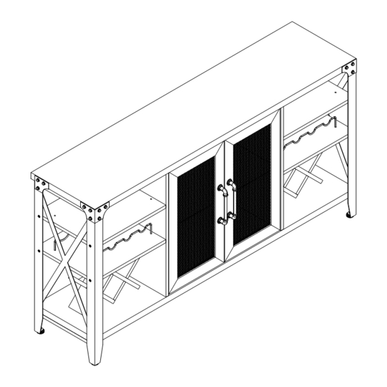
Board Identification Not actual size BOTTOM LEFT PARTITION Qty:1 Qty:1 Qty:1 RIGHT PARTITION FIXED SHELF WINE BOTTLE RACK PLATE Qty:1 Qty:4 Qty:4 WINE BOTTLE RACK PLATE WINE BOTTLE RACK PLATE DOOR Qty:2 Qty:2 Qty:2 3-24... - Page 4 Board Identification Not actual size BACK PANEL LEFT FRAME RIGHT FRAME Qty:1 Qty:1 Qty:1 WINE CUP HOLDER FRONT WINE BOTTLE RACK REAR WINE BOTTLE RACK Qty:2 Qty:2 Qty:2 FOOT DECORATIVE IRON SHEET MIDDLE SHELF DECORATIVE ANGLE IRON Qty:2 Qty:2 Qty:2 Qty:1 4-24...
- Page 5 Board Identification Not actual size 5-24...
-
Page 6: Part List
Part List Ø15X11mm Ø6.5X35mm Ø8X30mm Ø6.3X40mm CAM LOCK CAM BOLT WOOD DOWEL SCREW spare:2 spare:2 spare:2 spare:1 Ø3.5X14mm Ø3X14mm M6X20mm M6X30mm SCREW SCREW SCREW SCREW spare:2 spare:2 spare:2 spare:1 M4X20mm Ø4X14mm 186X37X26mm Ø35mm SCREW SCREW HANDLE DOOR HINGE spare:1 spare:1 15X12X12mm 30X20X10mm 4X65mm... - Page 7 Part List SCREW:Ø3.5*14 Ø10mm Ø17X15X10mm 19X14X9mm SCREW:Ø3.2*30 X1 set WRENCH TIPPING RESTRAINT LAMP CLIP LAMP LINE BUCKLE HARDWARE KIT Cam Lock Fastening System Insert the cam bolt into the hole first, then insert the cam lock and lock it. The opening must point toward the edge of the board 7-24...
- Page 8 STEP1 Ø6.5X35mm Ø8X30mm E X 4 8-24...
- Page 9 STEP2 Ø6.5X35mm Ø15X11mm The raw edge is aligned with the direction of the hole Proper orientation of CAM LOCK 9-24...
- Page 10 STEP3 Ø15X11mm Proper orientation of CAM LOCK 10-24...
- Page 11 STEP4 Ø6.3X40mm M6X30mm 4X65mm M6*30mm Before you install this screw, please make sure the screw size is M6*30mm 11-24...
- Page 12 STEP5 Ø6.5X35mm 30X20X10mm Ø3X14mm Ø3.5X14mm 17X15X10mm 12-24...
- Page 13 STEP6 Ø4X14mm 19X14X9mm X1 set First stick the back of the crimping device to the surface of the panel. Then Note: please remove the clip the light line into the protective film on the surface of crimping device the lamp before installing the lamp.
- Page 14 STEP7 M6X30mm 4X65mm Ø15X11mm Before you install this screw, please make sure the screw size is M6*30mm M6*30mm Proper orientation of CAM LOCK 14-24...
- Page 15 STEP8 M6X20mm Ø10mm 28mm 43mm 15-24...
- Page 16 STEP9 Ø3X14mm 19X14X9mm Stick the back of the crimping device to the back of the metal frame Before attaching the back panel, be sure that the unit is at 90°. 90° 16-24...
- Page 17 STEP10 15X12X12mm First push the glass plate along the clip in parallel, and then tighten the lower screw clockwise as shown in the figure. Tighten with a cross screwdriver. 17-24...
- Page 18 STEP11 M4X20mm 186X37X26mm Ø3.5X14mm Ø35mm I X 2 18-24...
- Page 19 STEP12 To adjust the vertical height. Loosen the four screws "A" on both hinges. Two of them are usually in slotted holes which allows you to adjust up or down by a few mm. Then tighten back up. To adjust depth. Loosen screw "B"...
- Page 20 STEP13 Ø8X30mm Ø6.3X40mm step1 step2 Notch direction Notch direction Notch direction step3 Effect after assembly Notch direction Notch direction 20-24...
- Page 21 STEP14 You can put the wine bottle holder in the position, as shown in the figure. Wine cup holder (rear) Wine cup holder (front) 21-24...
- Page 22 STEP15 Description of switch function. 1. Power on/off:Press and hold the power button. 2.Change the mode:Short press the power button.(Multiple mode options:Static Red/Static Green/Static Blue/Static White/Multicolor Blinking/Multicolor Breathing/Red Breathing/Blue Breathing/Green Breathing) 3.Adjust the flashing speed:Short press the cycle button. 4.Adjust the brightness:Press and hold the power button and short press the cycle button meanwhile.
- Page 23 STEP16 ON/OFF Remote control instructions Mode switch+/Previous mode MODE /MODE: Mode switch-/Next mode Color cycle display mode DEMO: SPEED/ Adjust the flashing speed(Six speed mode) SPEED: COLOR/ COLOR: Switch color Adjust the brightness(Six speed mode) BRIGHT /BRIGHT: In addition, there are 7 colors, making up a total of 25 color modes. Before use, pull out the transparent card below.
- Page 24 STEP17 NOTE :The tipping restraint hardware included is for wooden stud wall construction. It must be attached to a wall stud. Depending upon your wall construction different SCREW : Ø3.2*30 We have included a set of tipping restraint hardware for anchor hardware maybe required.
Need help?
Do you have a question about the D8L235BR01 and is the answer not in the manual?
Questions and answers