Advertisement
Quick Links
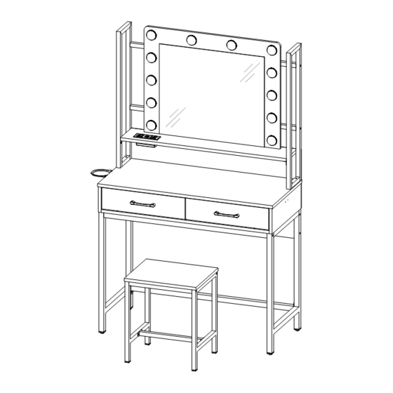
D3M531BS03
D3M531HZ03
As this item contains many parts, please read the installation
instruction carefully before installation . Please use tools
properly and carefully. If you have any questions about the
product and installation, please contact us.
service@vabchesofficial.com
Our professional after-sales team will serve you online all
day.
1-28
Advertisement

Related Manuals for VABCHES D3M531BS03


Summary of Contents for VABCHES D3M531BS03
- Page 1 D3M531BS03 D3M531HZ03 As this item contains many parts, please read the installation instruction carefully before installation . Please use tools properly and carefully. If you have any questions about the product and installation, please contact us. service@vabchesofficial.com Our professional after-sales team will serve you online all day.
-
Page 2: Before You Start
Before You Start Read through each step carefully and follow the proper order Separate and count all your parts and hardware Give yourself enough room for the assembly process Have the following tools: Flat Head Screwdriver, #2 Phillips Head Screwdriver and Hammer Caution: If using a power drill or power screwdriver for screwing, please be aware of to slow down and stop when screw is tight. -
Page 3: Board Identification
Board Identification Not actual size LEFT SIDE PANEL RIGHT SIDE PANEL Qty:1 Qty:1 Qty:1 MIDDLE PANEL FRONT CROSS MEMBER REAR CROSS MEMBER Qty:1 Qty:1 Qty:1 REAR LOWER PANEL DRESSING MIRROR FIXED SHELF Qty:1 Qty:1 Qty:1 3-28... - Page 4 Board Identification Not actual size BACK PANEL LEFT DRAWER FRONT RIGHT DRAWER FRONT Qty:1 Qty:1 Qty:1 LEFT DRAWER SIDE RIGHT DRAWER SIDE DRAWER BACK Qty : 2 Qty:2 Qty:2 DRAWER BOTTOM STOOL PANEL LOWER LEFT FRAME Qty:2 Qty:1 Qty:1 4-28...
- Page 5 Board Identification Not actual size LOWER RIGHT FRAME UPPER LEFT FRAME UPPER RIGHT FRAME Qty:1 Qty:1 Qty:1 RAIL RAIL RAIL Qty:2 Qty:1 Qty:1 SIDE FRAME OF STOOL RAIL RAIL Qty:2 Qty:2 Qty:1 5-28...
- Page 6 Board Identification Not actual size 6-28...
-
Page 7: Part List
Part List 15X9.5mm ∅ 6.5X35mm ∅ 6X30mm ∅ 6.3X50mm CAM LOCK CAM BOLT WOOD DOWEL SCREW spare:2 spare:2 spare:3 ∅ 4X35mm Ø3.5*14mm Ø3*14mm M6X12mm SCREW SCREW SCREW SCREW spare:2 spare:3 spare:2 spare:2 M6X30mm M6X35mm M6X40mm M4*18mm SCREW SCREW SCREW SCREW spare:2 spare:2 131*13*21mm... - Page 8 Part List 14" 14" 14" 14" 350mm 350mm 17CR 17DL 17DR 17CL LEFT CABINET MEMBER RLGHT CABINET MEMBER LEFT DRAWER RUNNER RLGHT DRAWER RUNMER Ø4X14mm ∅ 3X12mm X1 set TIPPING RESTRAINT SCREW SCREW SOCKET HARDWARE KIT spare:1 spare:1 HAIR DRYER RACK Cam Lock Fastening System Insert the cam bolt into the hole first, then insert the cam lock and lock it.
- Page 9 STEP1 14" 14" 350mm 350mm Ø3.5X14mm 17CL 17CR 17CL 17CR 9-28...
- Page 10 STEP2 14" 14" 350mm 350mm Ø3.5X14mm 17CL 17CR 17CR FLIP OVER 17CL 10-28...
- Page 11 STEP3 Ø6.5X35mm Ø6X30mm 11-28...
- Page 12 STEP4 Ø6.5X35mm Ø6X30mm Ø4X35mm Finished edge 12-28...
- Page 13 STEP5 Ø15X9.5mm Ø6.5X35mm Proper orientation of CAM LOCK 13-28...
- Page 14 STEP6 Ø15X9.5mm Ø6X30mm Proper orientation of CAM LOCK 14-28...
- Page 15 STEP7 Ø6.3X50mm M6X40mm 4X65mm M6X12mm Before you install this screw, please make sure the screw size is M6*40mm M6X40mm M6X12mm Please tighten the screws to 80% first, and tighten all screws 100% after all parts are assembled. Before you install this screw, please make sure the screw size is M6*12mm 15-28...
- Page 16 STEP8 15X9.5mm M6X35mm 4X65mm Please tighten the screws to 80% first, and tighten all screws 100% after all parts are assembled. Before you install this screw, please make sure the screw size is M6*35mm M6X35mm Proper orientation of CAM LOCK 16-28...
- Page 17 STEP9 Ø6X30mm 20X20X16mm M6X12mm 4X65mm Before you install this screw, please make sure the screw size is M6*12mm M6X12mm 17-28...
- Page 18 STEP10 M6X40mm 4X65mm M6X12mm Before you install this screw, please make sure the screw size is M6*40mm M6X40mm Please tighten the screws to 80% first, and tighten all screws 100% after all parts are assembled. M6X12mm Before you install this screw, please make sure the screw size is M6*12mm 18-28...
- Page 19 STEP11 M6X30mm 4X65mm Ø4X14mm Before you install this screw, please make sure the screw size is M6*30mm M6X30mm Before you install this screw, please make sure the screw size is M6*30mm M6X30mm Please tighten the screws to 80% first, and tighten all screws 100% after all parts are assembled.
- Page 20 STEP12 Ø3X14mm Ø3.5X14mm X1 set Ø3.5*14mm Make sure the holes in the middle row of the back panel are aligned with the holes in the back of the top panel, lock the screws in the middle row, and finally lock others. 20-28...
- Page 21 STEP13 Ø6.5X35mm Ø6X30mm Ø4X35mm 21-28...
- Page 22 STEP14 Ø15X9.5mm Proper orientation of CAM LOCK 22-28...
- Page 23 STEP15 14" 14" Ø3.5X14mm 350mm 350mm 17DL 17DR K & L 23-28...
- Page 24 STEP16 M4X18mm 131X13X21mm Ø3X12mm Cabinet Slide Drawer Slide 24-28...
- Page 25 STEP17 M6X40mm M6X12mm M6X30mm M6X40mm Before you install this screw, please make sure the screw size is M6*40mm M6X12mm Before you install this screw, please make sure the screw size is M6*12mm Before you install this screw, please make sure the screw size is M6*30mm M6X30mm Please tighten the screws to 80% first, and tighten...
- Page 26 STEP18 X1 set Pass the bulb wire through the pre punched plate, then gently press the bulb and make it adhere to the plate. Tear off a layer of 3M polyethylene foam. 26-28...
- Page 27 STEP19 1Connect the adjacent bulbs successively through the opposite wire head slot (corresponding to the same color line). 2When making up, you can use the switch to turn on or off the light. The dressing table brings you 3 color temperature light modes,touch the button you can easy light up the mirror and change colors to meet your different needs, long press to adjust the brightness.
- Page 28 STEP20 NOTE :The tipping restraint hardware included is for wooden stud wall construction. It must be attached to a wall stud. Depending upon your wall construction different We have included a set of tipping restraint hardware for anchor hardware maybe required. Please contact your local this unit.
Need help?
Do you have a question about the D3M531BS03 and is the answer not in the manual?
Questions and answers