Rinnai ES750 Maintenance And Service Manual
Hide thumbs
Also See for ES750:
- Operation & installation manual (28 pages) ,
- Operation manual (20 pages) ,
- Operation and installation manual (20 pages)

Related Manuals for Rinnai ES750


Summary of Contents for Rinnai ES750
- Page 1 Models ES750 ES1500 ES1000 ES1800 ES1300 ES2200 Electric Fire Series Maintenance and service guide...
- Page 2 Improper installation, adjustment, alteration, service and maintenance can cause property damage, personal injury or loss of life. Help is here For more information about buying, using, and servicing of Rinnai appliances call: 0800 RINNAI (0800 746 624). Rinnai New Zealand Limited...
-
Page 3: Table Of Contents
Replacing the PCB ..........16 Wiring diagram .............17 Parts lists The exploded diagrams and parts lists have not been published in this manual due to the frequency in which they change. Please refer to the Rinnai website (rinnai.co.nz) for the latest spares PDF’s. -
Page 4: Specification
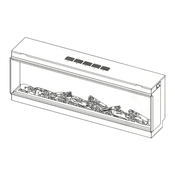
Specification summary Electric flame effect fires with realistic flame pattern, operated by remote control. Six models to choose from. Suitable for indoor domestic heating applications only. Features • Realistic glowing fuel bed with burning embers • Easy to install • Three independently controlled lighting effects •... -
Page 5: Dimensions
Dimensions Model Firebox width back - A Firebox total height - B Glass width - C ES750 780 mm 848 mm 750 mm ES1000 1030 mm 548 mm 1000 mm ES1300 1330 mm 548 mm 1300 mm ES1500 1530 mm... -
Page 6: Repair And Maintenance
Repair and maintenance The Rinnai ES fires are low maintenance and only require the glass to be cleaned, and dust removed from the vents and burn media. In case of repairs, it is recommended that cleaning is done at the same time. - Page 7 Remove lower glass retaining panel To be able to remove the glass, the lower retaining panel must be removed first using the magnet tool. 1. Position the magnet onto the panel and twist. 2. Using the magnet ring, pull, lift out the metal panel, and place to one side. Remove outer glass Place glass suckers either side of the glass panel, try and keep the position even so...
-
Page 8: Dismantling For Repair
Dismantling for repair To replace a number of components in the unit will require removing the fuel bed tray, side glass panels, and glass back panel. Remove fuel bed tray Remove the fuel bed tray by removing the screws and lifting the tray from the appliance. 8 | Electric Fires service manual: d1 01-24... - Page 9 Remove side glass panels The side glass panels can be easily removed by lifting up and out of the retainers. Remove back glass panel Using the glass suckers pull the bottom of the glass, tilt and remove from the unit. It may be necessary to loosen the top glass retaining bar.
-
Page 10: Replacing The Flame Spindle
Replacing the flame spindle • Remove the fuel bed tray • Remove side glass panels • Remove glass back panel Remove the flame silhouette panel. Then unscrew the spindle centre support to detach the rubber connector from the motor to remove the spindle 10 | Electric Fires service manual: d1 01-24... -
Page 11: Replacing The Transformer
Replacing the transformer • Remove the fuel bed tray • Remove side glass panels • Remove glass back panel The transformer can be disconnected and unscrewed from the appliance. Electric Fires service manual: 01-24 | 11... -
Page 12: Replacing The Downlight Led Board
Replacing the downlight LED board • Remove the fuel bed tray • Remove side glass panels • Remove glass back panel Remove the downlight LED board by removing the two screws either side. Carefully lower the downlight LED board and unplug the unit. Connect a replacement downlight LED board and secure using the two screws, 12 | Electric Fires service manual: d1 01-24... -
Page 13: Replacing The Fan Heater Unit
Replacing the fan heater unit 1. Remove the downlight LED board by removing the two screws either side. 2. Carefully lower the downlight LED board and unplug the unit. 3. Remove the screws securing the fan heater panel and lower it. Unplug the fan heater unit and remove. -
Page 14: Replacing The Flame Led Boards
Replacing the flame LED boards • Remove the fuel bed tray • Remove side glass panels • Remove glass back panel Remove silhouette panel. Unscrew spindle centre support and detach rubber connector from motor to remove the spindle. (refer page 10). The LED boards can now be unscrewed and disconnected. 14 | Electric Fires service manual: d1 01-24... -
Page 15: Replacing The Flame Motor
Replacing the flame motor • Remove the fuel bed tray • Remove side glass panels • Remove glass back panel Remove silhouette panel. Unscrew spindle centre support and detach rubber connector from motor to remove the spindle. (refer page 10). Unscrew the three mounting screws from the motor and gently lift away. -
Page 16: Replacing The Manual Control
Replacing the manual control Remove the screws from the PCB panel and lower to reveal the connections. Remove the screws from the manual control panel, there are two screws above and two screws underneath. Move the manual control panel out of the unit and disconnect it. 16 | Electric Fires service manual: d1 01-24... -
Page 17: Replacing The Pcb
Replacing the PCB Remove screws from the PCB panel and lower to reveal connections. Disconnect and replace. Electric Fires service manual: 01-24 | 17... -
Page 18: Wiring Diagram
Wiring diagram 18 | Electric Fires service manual: d1 01-24... - Page 20 Rinnai.co.nz Tel: 0800 746 624 http://www.youtube.com/rinnainz http://facebook.com.rinnainz Rinnai Electric Fires service manual 01-24...
Need help?
Do you have a question about the ES750 and is the answer not in the manual?
Questions and answers