
Related Manuals for LEMKEN TITAN 18


Summary of Contents for LEMKEN TITAN 18
- Page 1 OPERATING INSTRUCTIONS SEMI-MOUNTED REVERSIBLE PLOUGH TITAN 18 en-GB | Item no. 17514590 | BA 01/01.2021...
- Page 2 Pass these instructions to all users / owners. Original instructions © 2021 | This documentation is copyright protected. The copyright remains with LEMKEN GmbH & Co. KG, Weseler Strasse 5, D-46519 Alpen. The texts, diagrams and drawings must not be duplicated, distributed or disclosed in any other way,...
-
Page 3: Table Of Contents
Table of contents Table of contents About these instructions............................1 1.1 Introduction................................. 1 1.2 Target groups..............................2 1.3 Applied symbols..............................2 1.3.1 Design of warning signs..........................2 1.3.2 Signal words and hazard statements...................... 3 1.3.3 Warning of property damage........................3 1.3.4 Other notices and information........................ - Page 4 Table of contents 3.12 Additional tools............................. 25 3.13 Disc coulter..............................26 3.14 Subsoiler................................27 Attaching..................................28 4.1 Checking suitability of the tractor......................28 4.2 Preparing the tractor............................29 4.3 Preparing the machine..........................30 4.4 Attaching the machine..........................30 Road travel................................. 33 5.1 Information on road travel...........................
- Page 5 Table of contents 6.4 Working with the machine.......................... 62 6.4.1 Standard procedure............................ 62 6.4.2 Driving on the headland........................... 63 Cleaning and care..............................64 7.1 After working in the field..........................64 7.2 Cleaning with high-pressure cleaner....................... 64 Detaching................................... 65 8.1 Detaching the machine..........................65 Maintenance and repair work..........................
- Page 6 Table of contents 12.6 Connection data............................81 12.6.1 Electrical connections..........................81 12.6.2 Hydraulic connections..........................82 12.7 Noise, airborne sound..........................82 12.8 Operating materials............................. 82 12.9 Tyres and wheels............................83 12.10 Permitted shear bolts..........................83 12.11 Connecting equipment at the implement..................83 Index.....................................
-
Page 7: About These Instructions
About these instructions About these instructions Introduction Observe the operating instructions These operating instructions are important and belong to the machine's scope of delivery. These operating instructions must be available to the user at the place of use. Always read chapter "Safety" before using the machine for the first time. -
Page 8: Target Groups
About these instructions Initial commissioning These operating instructions do not describe initial commissioning. INFORMATION Prior to operation, initial commissioning and instruction in operation, setting and maintenance must have been carried out by the dealer. Target groups The target groups of these operating instructions are operators, users and service personnel of the machine. -
Page 9: Signal Words And Hazard Statements
About these instructions 1.3.2 Signal words and hazard statements The following signal words and hazard statements are used to label warning signs and to warn of residual risks: DANGER Indicates an immediate hazardous situation If the hazardous situation is not avoided, it will result in death or serious injury. -
Page 10: Symbols And Text Markings
About these instructions 1.3.5 Symbols and text markings Symbol, text marking Meaning In front of and in texts Marking for routine maintenance ● tasks Activities that demand the help of service staff. Listing Position numbers [1], Example: ‘Settings’ Software element Example: [OK] Softkey, key, switch and button [kg]... -
Page 11: Language Setting
About these instructions 1.3.7 Language setting The language of the control is coupled with the language setting of the ISOBUS operation terminal. If a set language is not available for the control, English is displayed automatically. 1.3.8 Operation with several ISOBUS operation terminals If several ISOBUS operation terminals are connected to the machine via an interface, machine operation can be switched to any ISOBUS opera‐... -
Page 12: Safety
Safety Safety Intended use The machine is used for soil cultivation on agricultural land. It may only be used in accordance with the recognised rules of good agricultural practice. Limitations The permitted working depth is limited to the cultivatable soil horizons. Not intended for use in the following cases: On very or deep-frozen soils In soil horizons with unweathered bedrock... - Page 13 Safety Operating instructions The operating instructions are part of the machine. The machine is intended exclusively for use in accordance with these operating instructions. Applications of the machine not described in these oper‐ ating instructions may result in personal injury or death or property damage.
-
Page 14: Personnel Qualification Requirements
Safety Personnel qualification requirements Operator The operator is obliged to inform all the users about correct application of the machine and the respective hazards. This can be done on the basis of these operating instructions. The operator is responsible for ensuring that the operating instructions are always available at the machine and that the users observe the operating instructions. - Page 15 Safety Moving hazardous area The hazardous area of the machine during operation. Moving hazardous area The hazardous area includes the area in the direction of travel across the entire width of the machine. NEVER climb out of the tractor while it is moving. ►...
-
Page 16: Workplaces And Passengers
Safety Parked machine The parked machine may overturn. This may result in fatal or serious injuries. Park the machine in transport position. ► Park the machine on firm and level ground only. ► Place a plate (metal, wood, stone) with sufficient carrying capacity ►... -
Page 17: Technically Perfect Condition
Safety Observe the hazardous areas. ► Pay attention to other persons in the vicinity of the machine. ► Passengers Passengers may fall from the machine and seriously injure themselves. Scattered objects may hit and injure passengers. NEVER allow persons to ride along on the machine. ►... - Page 18 Safety Danger due to damage to the Damage to the machine can impair the operational safety of the machine machine and cause accidents. This may result in fatal or serious injuries. To ensure that the machine is in a safe condition, carry out the fol‐ lowing measures: Inspect the machine according to the maintenance schedule ►...
-
Page 19: Safe Handling
Safety Safe handling 2.6.1 Personal protective equipment Carrying and wearing protective equipment is an important safety component. Lack of or inappropriate protective equipment increases the risk of damage to health and injury to persons. For certain work on the machine, the following protective equipment is required in addition to suitable workwear: Safety gloves Use protective equipment as follows:... -
Page 20: Safety Devices And Labels
Safety Safety devices and labels For the protection of the user, other persons and the machine, the machine is equipped with special safety devices, e.g.: Stabilisation The actual equipment of the machine with safety devices depends on the country-specific rules and regulations. Ä... -
Page 21: Design And Description
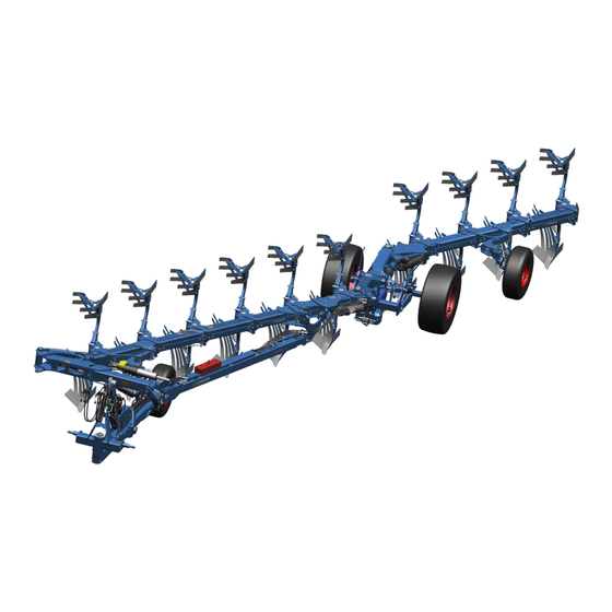
Design and description Design and description Machine overview INFORMATION Depending on the equipment of the machine and country-specific requirements, the assembly groups described below may be present on the machine. Headstock Semi-mounted wheels Hydraulic ram for the traction increase device Trailer Turnover device Plough bodies... -
Page 22: Machine Safety
Design and description Machine safety 3.2.1 Position of the label 3.2.2 Meaning of the labels This section explains the information and warning signs that have been affixed to the machine. Reading the operating instructions Incorrect use or operation of the machine can result in death or serious injury. - Page 23 Design and description Turn off the engine A tractor with the engine running can cause unintentional movements. This may even be fatal or result in serious injuries. Before maintenance and repair work: Turn off the engine. ► Engage the parking brake of the tractor. ►...
-
Page 24: Safety Devices
Design and description Hydraulic equipment Connection overview of hydraulic hoses P0/T0 - hydraulic overload safety device - comfort version P1/T1 - turnover device (OF-reverse rotation) P2/T2 - hydraulic working width adjustment P3 - lifting device for the trailer P4/T4 - lifting device for the rear plough frame P6/T6 - hydraulic adjustment of the front furrow width Positioning points for jack Positioning points for jack... - Page 25 Design and description Lighting equipment Example of rear lighting equipment Warning boards Lateral reflectors LED lighting equipment Rear reflectors Warning board Depending on national regulations, a warning board may be required for slow-moving vehicles. 3.2.3.2 Stabilisation Stands The stands ensure that the dismantled implement is stable. When mounted, the stands are folded up again.
- Page 26 Design and description 3.2.3.3 Protection against unauthorised use The protection against unauthorised use ensures that only authorised persons can attach the machine to a tractor. The following versions are available: Protection against unauthorised use for cross shafts Protection against unauthorised use for ball-shaped couplings Protection against unauthorised use for drawbar eyes en-GB | Item no.
-
Page 27: Type Plate
Design and description Type plate The machine is marked with a type plate. The machine type is uniquely defined on the type plate. Sample design of a type plate (standard) Series Type designation Model year Serial number Year of manufacture Vehicle class, subclass, speed index EU type approval number Vehicle identification number. -
Page 28: Headstock
Design and description Headstock Headstock The headstock with cross shaft and top link pin has been Cross shaft designed according to standard ISO 730. Top link pin The headstock is used to connect the implement to the three-point linkage of the tractor. The implement is available with different cross shafts. -
Page 29: Turnover Device
Design and description Turnover device The machine is equipped with the hydraulic on-land turnover device Turnover device Turnover ram , which turns the plough frame via two turnover rams Frame swing-in The turnover device features an electronic turning control. The turning control ensures via the sensor (SF) at the trailer that the plough frame can only be turned when the rear plough frame is lifted. -
Page 30: On-Land Version
Design and description Double-cutting shearing protection Shear bolt Double-cutting shearing protection in the leg brackets is standard on all implements. Shear bolts are replaced when broken. Hydraulic overload safety device Hydraulic overload safety device With the hydraulic overload safety device the release force is adjusted between a minimum and a maximum release pressure. -
Page 31: Additional Tools
Design and description Dural Mouldboard blade The following belongs to the plough body: Shin Mouldboard, divided into shin and mouldboard blade or slat Shin Share wing Share wing Share, divided into share wing and point Point Frog Point Landside Slat Frog Landside 3.12... -
Page 32: Disc Coulter
Design and description Sword coulter 3.13 Disc coulter The large disc coulters ensure a clean furrow. Examples: Equipment with disc coulter Disc coulter, smooth smooth, stalk rigid Stalk, rigid Disc coulter, smooth Equipment with disc coulter smooth, stalk rigid, adjustable lengthwise Stalk rigid, adjustable lengthwise en-GB | Item no. -
Page 33: Subsoiler
Design and description 3.14 Subsoiler Example: Subsoiler en-GB | Item no. 17514590 | BA 01/01.2021... -
Page 34: Attaching
Attaching Attaching Checking suitability of the tractor WARNING Risk of accident due to unsuitable tractor If the tractor is not suitable for the machine, components of the machine may be overloaded and the tractor- machine combination may not be steered safely. This may result in accidents with injuries or death of per‐... -
Page 35: Preparing The Tractor
Attaching Preparing the tractor Keep the tractor documentation The tractor is prepared before attaching the machine. For this purpose, ready the user must carry out various checks and adjustments. The following information about the tractor is required: Air pressure of tyres Instructions for adjusting the lifting rods Instructions for adjusting the check chains or stabilisers WARNING... -
Page 36: Preparing The Machine
Attaching Preparing the machine Headstock attachment position The headstock has 2 attachment positions: Cross shaft towards the rear (standard position) Cross shaft towards the front Swivelling the headstock increases or decreases the distance between the plough’s pivot point and the tractor’s rear axle. Select the small distance to minimise side pull. - Page 37 Attaching Preconditions: Ä The tractors is suitable for operating the machine, see page 28. Ä The tractor is prepared, see page 29. Attachment 1. Switch the hydraulics of the three-point linkage to position control for attachment. 2. Back the tractor up to the machine. ð...
- Page 38 Attaching 12. Attach the headstock to the top link: Select attachment position for the top link. Ä ‘Headstock attachment position’ on page 30 Remove top link pin from the parking position Connect the headstock and the top link with the top link pin. Only use the top link pin supplied with the machine.
-
Page 39: Road Travel
Road travel Road travel Information on road travel Laws on driving on public roads differ in many countries. Pay particular attention to local laws and regulations regarding the ► following points: Driving on public highways Maximum permissible transport height Maximum permissible transport width Maximum permissible transport weight Lighting equipment Markings... -
Page 40: Adjusting The Suspension
Road travel Checklist Subsoilers The subsoilers must be switched to transport position. Ä Sub‐ soilers, page 35 Control units of the tractor Observe the instructions of the tractor manufacturer. To avoid unintentional movements of the implement: Lock the tractor control units. 5.2.1 Adjusting the suspension Make sure that the shut-off valve of the traction increase device is... -
Page 41: Subsoilers
Road travel 5.2.3 Subsoilers Before driving on the road: Move the subsoilers to the transport posi‐ tion. DuraMaxx (left) and Dural (right) Subsoiler 1. Release the locking bar (DuraMaxx) or pin (Dural) Holder 2. Pull the subsoiler Locking bar out of the holder 3. -
Page 42: Operation
Operation Operation Basic operation 6.1.1 Operating the stands Fold out the stands 1. Raise the implement approx. 1...5 cm using the three-point linkage. 2. Dismantle the pin. 3. Swivel down the stands. 4. Fix the stands in the operating position with the pins. 5. - Page 43 Operation Pressure gauge 3. In order to apply pressure to the bottom turnover ram with the Hydraulic ram control unit: Switch the control unit to the first pressure position. ð The plough frame is turned. 4. After turning the plough frame over the centre position = approx. 120°...
-
Page 44: Moving The Plough From Operating Position To Transport Position
Operation 6.1.3 Moving the plough from operating position to transport position 1. Lift the rear plough frame completely. 2. Lift the three-point power lift of the tractor. 3. Turn the plough to the half-rotated position = centre position. 4. Align the stabilisers parallel to the ground. ð... -
Page 45: Changing The Setup State
Operation 6. Machine with frame swing-in: Dismantle the pin of the frame swing-in. Close the shut-off valves at the turnover ram. Open the shut-off valve at the hydraulic ram of the frame swing-in. With the additional control unit of the turnover device: Swing out the frame swing-in. -
Page 46: Mounting The Wide Furrow Cutter
Operation 6.2.3 Mounting the wide furrow cutter Wide furrow cutter The wide furrow cutter widens the furrow of the last plough body. √ Application: light to medium soils ► Mount the wide furrow cutter at the last plough body. Adjusting the machine 6.3.1 All adjustments at a glance The following table shows the adjustments that the user can make at... -
Page 47: Adjusting The Operating Pressure For The Traction Increase Device
Operation Adjustment options at the machine Adjustment Trashboard Ä Adjusting the trashboard , page 52 Skimmers Ä Adjusting the skimmer , page 54 Disc coulter Ä Adjusting the disc coulter, page 56 6.3.2 Adjusting the operating pressure for the traction increase device Check the operating pressure Precondition: √... -
Page 48: Adjusting The Working Depth
Operation Change the operating pressure 1. Set the additional control unit for the semi-mounted wheel to "T". ð The plough is lowered. 2. Draw the plough into the ground. ð The current operating pressure is shown on the pressure gauge 3. - Page 49 Operation Standard procedure 1. Switch the hydraulics for the rear lifting gear of the tractor to posi‐ tion control. 2. Preset the position of the support wheel, to do so: Lower the implement to the ground. Set the position of the support wheel. –...
-
Page 50: Adjusting The Inclination
Operation Adjust the working depth at the trailer Pin adjustments are available on the left and right for the depth adjustment at the trailer. The adjustments on both sides must be iden‐ tical. 1. To relieve the pins of the pin adjustment: Extend the hydraulic ram of the trailer slightly. -
Page 51: Adjusting Front Furrow Width
Operation Inclination adjustment The inclination is adjusted mechanically via two adjusting screws The right and left-hand sides are adjusted separately. 1. For the side being adjusted: Turn the plough frame 120...130°. ð The rocker is lifted off the adjusting screw 2. -
Page 52: Adjusting The Draw Point Height
Operation O-operation The distance between the tractor and furrow edge determines the front furrow width. 6.3.6 Adjusting the draw point height Applications: Too much slippage while working Front axle has been relieved too much while working Preconditions: √ The implement is mounted at the tractor. √... - Page 53 Operation Eccentric plate Changing pitch angle: 1. Undo the nut The eccentric plate can be rotated. Eccentric plate 2. Undo the nut The plough body can be swivelled around this pivot point. Target Pitch Adjustment angle Improved Larger Notch on the eccentric plate penetration pitch downwards...
- Page 54 Operation 3. Adjust the remaining plough bodies, according to the reference dimension. The pitch angle is adjusted via the two adjusting screws , . When delivered, the plough bodies are mounted at an average pitch angle to the ground. Changing pitch angle: 1.
-
Page 55: Adjusting The Working Width Of The Plough Bodies
Operation 6.3.8 Adjusting the working width of the plough bodies Hydraulic working width adjustment The working width of the machine is infinitely adjustable. Adjustment range per body Interbody clearance [cm] [cm] 30...55 The working width of the plough bodies is adjusted via the tractor. The hydraulic rams for adjusting the working width are con‐... - Page 56 Operation Mechanical working width adjust‐ The working width of the implement can be set in four adjustments. ment Working width per body Interbody clear‐ ance [cm] The working width is adjusted by adjusting the individual plough Screw bodies and the position of the touch wheel. The leg brackets of the Screw individual plough bodies have holes for 4 different positions.
-
Page 57: Landside
Operation 6.3.9 Landside Only possible with DuraMaxx plough bodies Landside Screw To optimise guidance on slopes, move the landside V1 to a lower Screw position. INFORMATION Set the landsides on all the plough bodies to the same position. 1. Undo the screw 2. -
Page 58: Adjusting The Working Depth Of The Subsoilers
Operation 6.3.10 Adjusting the working depth of the subsoilers DuraMaxx (left) and Dural (right) Subsoiler 1. Slide the subsoiler into the holder from below. Holder 2. Secure the subsoiler with a locking bar (DuraMaxx) Locking bar or pin (Dural) 3. To change between the two positions: Release the locking bar or the pin Move the subsoiler... - Page 59 Operation DuraMaxx equipment Trashboard 1. Align the trashboard using the slots on the holder Holder 2. Screw the trashboard to the holder. 3. Align the holder using the slots on the leg Slots 4. Screw the holder to the leg. Slots Slots Slots...
-
Page 60: Adjusting The Skimmer
Operation Support screw Lock nut 6.3.12 Adjusting the skimmer The skimmer has the following setup options: Working depth Stalk position Projection angle Working depth Target: Distance The required working depth of the skimmer is approx. 5 to 10 cm. – For a plough working depth of 25 cm, this results in a distance (skimmer point to plough body point) of approx. - Page 61 Operation 6. Secure the pin with linch pin Stalk position To optimise the position of the skimmer for the respective operating conditions: Change the stalk position. 1. Undo the bolted connections 2. Move the stalk to the required position. Changing the stalk Effects position More free space between the...
-
Page 62: Adjusting The Disc Coulter
Operation Projection angle: 1. Release and pull out the pin 2. Swivel the skimmer to the required position. 3. Swivel the lug Align the holes in the lug and the swivelling bracket 9 10 Skimmers 4. Connect the lug and the swivelling bracket with the pin Stalk Swivelling bracket 5. - Page 63 Operation DANGER Stored mechanical energy Spring-loaded disc coulters are preloaded. Uncontrolled release of mechanical energy accelerates components like a projectile. After each adjustment: – Retighten the loosened bolted connections. – Check whether the disc coulters can oscillate freely when viewed in the direction of travel. –...
- Page 64 Operation Side distance Side distance Targets: Working depth Disc coulters cut 2 cm to 3 cm wider than the trailing tools. Disc coulters run parallel to the landside of the plough body. Side distance to the landside of the plough body: approx. 2 to 3 cm Side distance to the landside of the plough body in combination...
- Page 65 Operation The lateral swivel area of the disc coulter is limited by the adjusting piece 1. Undo the screw 2. Turn the adjusting piece until the required position has been reached. 3. Retighten the screw . Ä Tightening torques, page 91 Ä Bolted connections, page 93 Disc coulter Disc coulter next to skimmer equipment...
-
Page 66: Adjusting The Hydraulic Overload Safety Device
Operation 6.3.14 Adjusting the hydraulic overload safety device Operating pressure With the operating pressure, the user can set when a plough body will move upwards or to the side to avoid an obstacle. The operating pressure to be set depends on the soil conditions. Minimum operating pressure 125 bar Maximum operating pressure... - Page 67 Operation Adjusting the comfort version Adjusting valve unit After connecting the adjusting valve unit to an additional control Rotary knob for max. operating pressure unit on the tractor, the system is ready to operate with the set min‐ Rotary knob for min. operating pressure imum and maximum operating pressure.
-
Page 68: Working With The Machine
Operation Working with the machine 6.4.1 Standard procedure 1. Position the tractor-machine combination. 2. Dismantle the lighting equipment. 3. Set the machine. 4. At a machine with a hydraulic overload safety device: Switch the tractor control unit to the float position. ð... -
Page 69: Driving On The Headland
Operation 6.4.2 Driving on the headland 1. Before the headland: Lift the three-point power lift of the tractor. Use the additional control unit of the trailer to lift the machine completely out of the ground. Lift the rear plough frame completely out of the ground. Turn the machine to the centre position. -
Page 70: Cleaning And Care
Cleaning and care Cleaning and care After working in the field Remove soil from the implement. ► ð No soiling of roads: Soil remains in the field. Cleaning with high-pressure cleaner The user can clean the implement with the high-pressure cleaner. When cleaning, the user must observe the following: ATTENTION Damage due to cleaning with a high-pressure cleaner... -
Page 71: Detaching
Detaching Detaching Detaching the machine Preconditions: √ Parking space: Solid, level floor that offers sufficient carrying capacity √ Subsoilers are in the transport position. √ The machine is in the transport position. √ Shut-off valves of the two turnover rams are closed. √... - Page 72 Detaching 13. Uncouple the headstock from the top link. Remove the top link pin. Insert the top link pin into the hole Secure the top link pin with a linch pin. 14. Unlock the cross shaft in the lower links. 15.
-
Page 73: Maintenance And Repair Work
Maintenance and repair work Maintenance and repair work Maintaining the machine properly Personnel Certain activities, e.g. working on hydraulic hoses, should only be car‐ ried out by service personnel. These activities are marked with the symbol and in the maintenance schedule in the SERVICE PERSONNEL column. -
Page 74: Maintenance
Maintenance and repair work Maintenance 9.2.1 Maintenance schedule Chap. Task to execute 9.2.2 Check the top link pin ● ● 9.2.3.1 Check tyres ● 9.2.3.1 Check air pressure ● 9.2.3.1 Check the wheel nuts ● ● ● 9.2.4 Checking hydraulic hoses ●... -
Page 75: Tractor Connection
Maintenance and repair work 9.2.2 Tractor connection Check the top link pin 1. Visual inspection of the top link pin for: Damage Wear 2. Replace damaged or worn top link pins. 9.2.3 Frame 9.2.3.1 Tyres and wheels Check tyres Visual inspection ►... -
Page 76: Hydraulics
Maintenance and repair work Check the wheel nuts Tighten the wheel nuts on the implement to the respective tight‐ ► ening torque. 9.2.4 Hydraulics Checking hydraulic hoses 1. Check hydraulic hoses for damage and leakages. ð Replace damaged or defective hydraulic hoses immedi‐ ately. -
Page 77: Electrics
Maintenance and repair work 9.2.5 Electrics Checking connector plugs and lines Perform visual inspection of the connector plugs and cables. ► Watch for bent or broken contact pins in the plugs. Watch for exposed places in cables. ð Repair damaged connector plugs or cable connections immediately or have them replaced. -
Page 78: Lubricating
Maintenance and repair work Lubricating 9.3.1 Lubrication schedule INFORMATION The lubrication points are colour coded on the machine. Chap. Task to execute 9.3.2 Lubricating positions (1) ● ● ● 9.3.2 Lubricating positions (2) ● ● ● 9.3.2 Lubricating positions (3) ●... -
Page 79: Grease Components
Maintenance and repair work Lubricating positions (1) Lubricate the lubricating positions of the lubricating position (1). ► Lubricating positions (2) Lubricate the lubricating positions of the lubricating position (2). ► Lubricating positions (3) Lubricate the lubricating positions of the lubricating position (3). ►... -
Page 80: 10 Troubleshooting And Error Correction
Troubleshooting and error correction 10 Troubleshooting and error correction 10.1 Find and eliminate errors correctly 10.1.1 Prior to troubleshooting at the implement 1. Park the tractor-device combination. 2. Secure the tractor-device combination to prevent it from rolling away. 3. When working on the folding implement: Fold out the folding parts of the implements or secure them against folding out. -
Page 81: Error - Cause - Remedies At A Glance
Troubleshooting and error correction 10.2 Error - Cause - Remedies at a glance Hydraulic equipment Fault description Cause Remedy The working widths of the plough The hydraulic rams Adjust the working widths of the plough bodies of the front plough frame and of have been retracted bodies completely to narrow and then the rear plough frame are not equal. -
Page 82: Replacing The Shear Bolt
Troubleshooting and error correction Fault description Cause Remedy Plough body shear bolt shears An incorrect shear bolt has been Use original shear bolts. off frequently. installed. INFORMATION To prevent the thread from being in the shear area: Always install the shear bolt head on the side of the plough facing the ploughed soil. - Page 83 Troubleshooting and error correction 6. Have the new shear bolt at the ready. Ä Chapter 12.10 ‘Permitted shear bolts’ on page 83 ATTENTION: Only use shear bolts that meet the specified dimen‐ sions and quality. Only these bolts provide effective protection against damage.
-
Page 84: Shutdown And Disposal
Shutdown and disposal 11 Shutdown and disposal 11.1 Shutdown When the implement can no longer be used, it is dismantled and broken down into its components. Special knowledge is required to dismantle the implement. CAUTION Risk of accidents due to discharge of stored energy Springs are under tension. -
Page 85: Technical Data
Working width of each plough body - Titan 18 33/38/44/50 (with 100 cm interbody clearance) [cm] Working width of each plough body - Titan 18 V 30 – 55 (with 100 cm interbody clearance) [cm] For determining the actual dimensions: Measure Take into account applicable national transport width regulations. -
Page 86: Permissible Mass And Loads
Technical data 12.3 Permissible mass and loads The maximum permissible total mass, drawbar load and axle load of the machine are listed on its type plate. If the load capacities of the wheels are lower than the permissible axle loads, the permissible axle load is limited to the permissible load capacity of the wheels. -
Page 87: Connection Data
Technical data 12.6 Connection data 12.6.1 Electrical connections CAUTION Damage due to overvoltage and undervoltage Overvoltage and undervoltage will result in malfunctions and destroy electrical and electronic components. – Ensure that the power supply of the implement is within the tolerance range. –... -
Page 88: Hydraulic Connections
Technical data 12.6.2 Hydraulic connections Hydraulic connections and control units Consumer Colour Code Hydraulic overload safety device Hydromatic - White P0 / T0 comfort version Turnover device P1 / T1 ● Hydraulic working width adjustment Green P2 / T2 ● Hydraulic depth adjustment - depth and trans‐... -
Page 89: Tyres And Wheels
Ä Tightening torques, page 91 Ä Bolted connections, page 93 12.11 Connecting equipment at the implement Permitted categories for cross shafts and top link pins Titan 18 Cross shaft category 3N Cross shaft category 3 Cross shaft category 3 3 (CAT 4 ball, L3, Z3–91... -
Page 90: Index
Index Index Draw point height Adjustment ......46 Additional tools ......25 Drawbar load, permissible . - Page 91 Index Maintain ......70 Prepare ......30 Replacing hoses .
- Page 92 Index Piston rods Setup state lubrication ......73 changing ......39 Pitch angle Shear bolt adjustment .
- Page 93 Index Tractor Check suitability ..... . . 28 Preparation ......29 Tractor connection Maintenance .
-
Page 94: Appendix
Appendix Appendix en-GB | Item no. 17514590 | BA 01/01.2021... -
Page 95: A Type Plate Variants
Type plate variants Type plate variants Series 14 EAC label Type designation 15 Company name and address of the manufacturer Model year 15a Address of the manufacturer Serial number 16 Company logo Year of manufacture 17 Manufacturer Vehicle class, subclass, speed index 18 Date of homologation EU type approval number 19 Type / Equipment / Version... - Page 96 Type plate variants en-GB | Item no. 17514590 | BA 01/01.2021...
-
Page 97: B Tightening Torques
Tightening torques Tightening torques General information about bolted connections 1. Identify screw connections. Check identification marking on the screw and nut if necessary. Check the description in the spare-parts list. 2. Secure screw connections with once loosened self-locking nuts against self-loosening. Use one of the following measures: Use new self-locking nuts. - Page 98 Tightening torques Screws and nuts made of V2A Diameter Tightening torque [Nm] 1.37 Wheel bolts and wheel nuts Diameter Tightening torque [Nm] M18x1.5 M20x1.5 M22x1.5 en-GB | Item no. 17514590 | BA 01/01.2021...
-
Page 99: C Bolted Connections
Bolted connections Bolted connections Bolted connections for service personnel No work by the user required The service personnel will find further notes and information on tight‐ ening torques, locking compounds and tightening procedures in the service documentation. Frame extension External thread Hexagon bolt M16 10.9 Internal thread Locknut NM16-8... - Page 100 Bolted connections Swivel bracket bearing External thread Countersunk bolts M16x30 - 10.9 Zn D7991 Internal thread Pins D35x180 2xM16x25 V Swivel bracket leg bracket bearing External thread Countersunk bolts M16x30 - 10.9 Zn D7991 Internal thread Pins D35x180 2xM16x25 V Leg bracket bearing External thread Countersunk bolts M16x30 - 10.9 Zn D7991...
- Page 101 Bolted connections Stalk plate bearing External thread Pin D40/ M30x1.5 Cr Internal thread Slotted nut M30x1.5 Adjusting piece attachment External thread Hexagon bolts M16x65 - 8.8 Zn DIN 931 Internal thread Locknuts NM16-8 Zn DIN 985 Adjusting piece attachment External thread Hexagon bolts M16x65 - 8.8 Zn DIN 931 Internal thread Locknuts NM16-8 Zn DIN 985...
- Page 102 Bolted connections Skim stalk bracket attachment External thread Hexagon bolts M16x** - 10.9/12.9 Zn Internal thread Hexagon nuts M16 DIN 934-10 Zn Skim stalk (1) External thread Hexagon bolts M20x** - 10.9 Zn Internal thread Hexagon nuts M20 DIN 934-10 Zn Skim stalk (2) External thread T-head bolts M16...
- Page 103 Bolted connections Wheel studs pendulum wheel External thread Wheel bolt M18x1.5, D19 REB Internal thread Wheel nut B18-10 DIN 74361 Tightening torque 290 Nm Locking compound Tightening procedure Electric screwdriver Notes Tightening sequence: Share wing attachment External thread M10x33 12.9 Internal thread Nut M10 Zn Tightening torque...
- Page 104 Bolted connections Plough body attachment External thread Countersunk bolts M20 12.9 Zn Internal thread Locknut NM20-8 Zn DIN 985 Tightening torque 400 Nm Locking compound Tightening procedure Torque wrench Notes Share wing / point attachment External thread Countersunk screws M12 12.9 Internal thread MU 10 Zn Tightening torque...
- Page 105 Bolted connections Mouldboard attachment External thread Countersunk screws M10 12.9 Internal thread Nut M10 10 Zn Tightening torque 60 Nm Locking compound Tightening procedure Impact driver Notes Landside wedge, sword coulter attachment External thread Countersunk screws M10 12.9 Internal thread Nut M10 10 Zn Tightening torque 60 Nm...
-
Page 106: D Cross Shaft Overview
Cross shaft overview Cross shaft overview To determine the cross shaft or lower link connection: Determine the dimensions shown in the sketch on the implement. Compare the dimensions with the data in the table. The category of the three-point linkage must match with the cate‐ gory of cross shaft or lower link connection. - Page 108 LEMKEN GmbH & Co. KG Weseler Strasse 5 D-46519 Alpen Telephone: +49 2802 81-0 Fax: +49 2802 81-220 Email: info@lemken.com Internet: www.lemken.com...
Need help?
Do you have a question about the TITAN 18 and is the answer not in the manual?
Questions and answers