
Subscribe to Our Youtube Channel
Related Manuals for Ulvac CR16B


Summary of Contents for Ulvac CR16B
- Page 1 YK16-0010-DI-002-02 取扱説明書 多段ルーツ式ドライ真空ポンプ 型 式 CR60B この製品をご使用になる前に必ずお読み下さい。また、 いつでもご使用できるように大切に保管して下さい。 株式会社アルバック 規格品事業部 http://www.ulvac.co.jp/...
- Page 3 準拠の宣言...
-
Page 4: 0.本製品を使用する前に
YK16-0010-DI-002-02 0.本製品を使用する前に このたびは幣社の製品をお買い上げいただき誠にありがとうございます。 本製品がお手元に届きましたら、念のため、ご注文の内容と同一であることおよび、輸送等による破損 がないことをご確認下さい。 このマニュアルには、本製品を安全にかつ性能を有効にご利用いただくために、適切な取扱方法 および適切な保守方法について記載しています。事前に本取扱説明書をお読みいただき、ポンプを正しく お使いください。 本製品を取り扱うには、ご使用になられる国や地域の安全に関する規則や法令(例えば消防法、電気 配線規定など)に従って設置および運用をしてください。従って、ご使用になられる国や地域で公的に有効 とされている一般的な安全教育(電気安全、荷役安全など)を受講する必要があります。安全教育を受けて いない方は、絶対に取り扱わないでください。オペレーターは、それらのトレーニングを受けている必要が 有ります。また、電気、機械、荷役、真空などに関する専門知識および技能、資格が必要です。 本製品は、このマニュアルが作成された現在の規則に適合するように設計されています。将来的にわた って規則の基準が変更された場合、その適合性を保障するものではありません。 本製品が組み込まれる装置が同じ規則に適合していない場合や、この製品自体に変更が加えられた 場合には、その性能と安全性を確保できない場合があります。弊社は、そのような場合の性能、安全の保 証(責任)はできません。お客様による製品の改造は、当社の保証範囲外ですので責任は負いません。 本製品の設置および取り外し作業を行う前には、すべてのエネルギー源(電気など)から製品を分離して ください。 本製品に使用されている一切の部品は、納入時の性能を維持しながら永久的に継続使用できるもので はありません。社会通念上想定される使用状況下に於いても、一定期間経過に伴い、必然的に性能に劣 化が生じ、製品のトラブルを発生させやすくなります。お客様において、お客様ご自身の使用状況を勘案の 上、トラブルを回避する予防保全の実現へのご協力をお願い申し上げます。 予防保全措置へご協力いただきますと、部品の磨耗故障に起因する本製品トラブルの発生確率を低減 でき、ひいては本製品トラブルに起因するダウンタイムおよび火災や他工程への影響等といった危険の 発生確率を低減できます。 重ねて予防保全の観点から、保守点検計画の構築およびそれに合わせた部品交換やオーバーホール 実施をお願い申し上げます。 取り扱う上で不明な点などがありましたら最寄りの営業所、代理店または弊社規格品事業部にご連絡くだ さい。 この取扱説明書はいかなる部分も第三者の為に当社の承諾なしに、 コピーするこ 注 意 とはできません。... -
Page 5: 0.1 安全シンボルマーク
YK16-0010-DI-002-02 0.1 安全シンボルマーク この取扱説明書及び製品の警告表示には守るべき事項を理解して頂くため、安全についてのシンボ ルマークを掲げております。シンボルに用いる言葉は次のように使い分けています。 0.2 安全シンボルマークの意味 取り扱いを誤った場合、使用者が死亡もしくは重傷になる差し迫った可能性を示 危 険 しています。 取り扱いを誤った場合、使用者が死亡もしくは重傷になる可能性を示していま 警 告 す。 取り扱いを誤った場合、使用者が中程度の傷害を受けるか、機械の重大な損傷 につながる可能性を示しています。機械の損傷を起こしたり、正常な動作を損ね 注 意 る可能性を示しています。 「重要」項目は、本システムの操作および保守作業上、特に知っておかなければ 重要 ならない情報や内容がある場合に記述します。 感電の危険があるため、電気安全に関してトレーニングが必要な作業 ポンプ停止直後は高温な箇所のため、ポンプの温度が下がっていることを確 認してから行う作業... -
Page 6: 0.3 安全上の注意事項
YK16-0010-DI-002-02 0.3 安全上の注意事項 作業項目別に危険を回避するための方法と危険なためやってはならない行動を示します。 本製品のお取扱、ならびに本取扱説明書について 本製品を末永くご利用頂くために、本製品の取付、操作、点検あるいは整備を する前に必ずこの取扱説明書をお読みいただき、安全上の注意事項、本製品 重要 の仕様及び操作方法に関わる事項を十分に理解して下さい。 本製品は、不活性ガス(空気、窒素、アルゴン)を排気することを前提としており、 他のガス(有毒ガス、燃焼ガス、支燃性ガス、腐食性ガス、爆発性ガス)を排気する 危 険 ことは、非常に危険です。 これらの性質を持つガスは排気しないでください。 燃焼ガス・支燃性ガス・爆発性ガスが、真空ポンプに吸引された場合、運転時だけ でなく、停止後も残留したガスや生成物が原因で発火・爆発することがあり、非常 危 険 に危険です。 これらの性質を持つガスは排気しないでください。 ご使用の危険物質の詳細を開示いただけない場合や、無害化処理が困難な 物質を排気した場合には、弊社でのメンテナンスその他の取扱いをお断りする 警 告 ことがあります。 製品及び取扱説明書の記述内容は、改良の為、仕様や価格等を予告なしに変 更する場合がありますので、御了承願います。変更は、取扱説明書の表紙右 警 告 上にある文書番号を更新し、改訂版として発行します。 本取扱説明書は製品をご使用になられる最終ユーザーに必ずお渡し下さい。 警 告 本製品を国外に輸出する場合には弊社宛てに一報頂きますと共に、輸出関連 法規の規定に従って必要な手続きをお取り下さいますようお願い致します。 警 告 不明な点がありましたら、ご購入頂きました営業所にお問合せ下さい。... - Page 7 YK16-0010-DI-002-02 保管・設置 ①本機は潤滑油を給油した状態で、工場より出荷していますので絶対に横倒し しないで下さい。 ②製品を段ボールから取り出しの際等、ポンプを持ち上げたりする場合は、クレ ーンなどの荷役機器を使用し、アイボルトを利用して、持ち上げて搬送するよ う指導して下さい。アイボルトは使用する前に異常がないことを確認して下さ い。 警 告 ③荷役作業および荷役機械の操縦は、技能資格を有した人以外は行わないで 下さい。 ④無理な操作や機器の整備が十分でない場合に、ポンプが落下したり、転倒し たりする可能性があります。ポンプの下には絶対に入らないで下さい。 搬入 ① 本製品はキャスターを装備していますが、キャスターを使っての長距離輸送 はしないで下さい。 ②本製品の質量は以下のとおりです。 警 告 CR 60 : 48 kg 搬送するためには安全基準以上の荷重が必要なため、腰を痛める可能性が あります。搬送は、荷役機器(例えば、移動式クレーン)で吊り下げて行うか、 パレットに載せ固定した後、パレットトラックで運んで下さい。 地震対策 固定が不十分だと転倒したり、移動したりして、周辺機器を破損させる可能性 があります。真空配管、電線については、規定のゆれに対して、配管が破れた 警 告 り、外れたりしない様、ゆれを吸収できる構造にしてください。...
- Page 8 YK16-0010-DI-002-02 吸排気口 配管 <取り付け> すべての危険エネルギーを遮断したことを確認してから、作業してください。 警 告 電源用配線 <取り付け> ①すべての危険エネルギーを遮断したことを確認してから、作業してください。 ②配線作業は、有資格者が行ってください。誤った配線工事は、火災の原因と なります。 ③配線工事は、ご使用になられる国や地域の安全に関する規則や法令に従い 警 告 (例:消防法、電気設備技術基準、内線規程)、正しく行って下さい。 ④アースは確実に接地して下さい。 ⑤専用の漏電遮断器を設置することを推奨いたします。故障や漏電のときに感 電する恐れがあります。 運転 ①運転中にポンプカバーは外さないでください。真空ポンプ本体やモータ、配管 は非常に高温になりますので触れないでください。人体が接触すると火傷の 危険があります。 警 告 ②排気口を塞ぐなど排気口側にガスの通過を妨害する機器をつけた状態で真 空ポンプを運転しないで下さい。真空ポンプ内圧が上昇して、ケーシングやオ イルレベルゲージが破裂・油漏れ、電動機の過負荷が発生する恐れがありま す。 ①危険場所(爆発性ガスによって、危険雰囲気を生成する恐れがある場所)で 使用しないで下さい。けが、火災の原因になります。 ②換気口の開口部に、指や物を入れないで下さい。感電、けが、火災等の恐れ があります。 注 意 ③真空ポンプの四方 1m以内には可燃物を絶対に置かないで下さい。火災の 恐れがあります。 ④本機は空冷式です。換気口から、0.3m以内に壁、障害物を置かないでくださ い。異常過熱による火傷、火災の恐れがあります。...
- Page 9 YK16-0010-DI-002-02 停止 運転停止後のしばらくは、真空ポンプやモータ、配管は非常に高温になります ので、ポンプカバーを外して触れないでください。人体に接触すると火傷の危険 警 告 があります。 点検・修理 ①点検・修理の時は、必ず 1 次側の MCCB(配線保護用遮断器)のスイッチを切 ってから作業を行って下さい。感電したり、急に真空ポンプが起動してけがを することがあります。 ②修理技術者以外の人は、絶対に分解したり修理・改造は行わないで下さい。 警 告 発火または異常動作してけがをしたり、感電する恐れがあります。 ③動かなくなったり異常がある場合は、事故防止のためすぐ 1 次側の MCCB (配線保護用遮断器)のスイッチを切り、ご注文先あるいは最寄のサービスセ ンターに必ず点検・修理をご依頼下さい。 電源用配線 <取り外し> 取り外し作業を行う前には、確実に電源から切り離してください。 警 告 吸排気口 配管 <取り外し> ①装置の設置マニュアルに従って、取り外してください。 ②運転停止後のしばらくは、吸排気口配管は非常に高温になりますので触れ 警 告 ないでください。ポンプの温度が下がってから取り外しを行って下さい。 ③ポンプの吸排気口を閉止フランジなどで完全に密閉してください。 搬出 ①本製品はキャスターを装備していますが、キャスターを使っての長距離輸送 はしないで下さい。...
-
Page 10: 0.4 本機に表示した警告ラベルの種類と説明および表示位置
YK16-0010-DI-002-02 0.4 本機に表示した警告ラベルの種類と説明および表示位置 本機には、警告箇所に警告ラベルを取り付けています。ポンプを運転する前に必ず確認して下さい。 この警告ラベルが取り付けてある部分の周囲は、感電のおそれがあります。 配線時、メンテナンス時には、1 次側の MCCB(配線保護用遮断器)のスイッチ を切ってから作業を行って下さい。 運転中や運転停止後のしばらくは、真空ポンプモータや電動機、配管は非常に 高温になりますので触れないでください。人体に接触すると火傷の危険があり ます。... -
Page 11: 0.5 ポンプの受入れと保管
YK16-0010-DI-002-02 0.5 ポンプの受入れと保管 0.5.1 開梱と受入れ時の点検 ①本機は潤滑油を給油した状態で、工場より出荷していますので絶対に横倒し しないで下さい。 ②製品を段ボールから取り出しの際等、ポンプを持ち上げたりする場合は、クレ ーンなどの荷役機器を使用し、アイボルトを利用して、持ち上げて搬送するよ う指導して下さい。アイボルトは使用する前に異常がないことを確認して下さ い。 警 告 ③荷役作業および荷役機械の操縦は、技能資格を有した人以外は行わないで 下さい。 ④無理な操作や機器の整備が十分でない場合に、ポンプが落下したり、転倒し たりする可能性があります。ポンプの下には絶対に入らないで下さい。 本製品がお手元に届きましたら、注意して開梱して下さい。まずご注文の内容と同一であることおよび 輸送等による破損がないことをご確認下さい。使用開始後にお知らせいただくと、有償となる場合があり ます。 細心の注意を払って出荷しておりますが、念のため荷づくりをとかれましたら、次のことをお確かめ下 さい。なお出荷時の梱包は、点検が終わるまでは捨てずにおき、異常があった際の返品の際にご利用下 さい。 ① ご請求の製品と一致しているか。 ② 付属品(取扱説明書、オプション部品)が付いているか。 ③ 輸送中に破損した箇所がないか。 重要 ④ 輸送中にネジやナット等に緩みが出ていないか。外れている所はないか。 万一、不具合がありましたら、当社営業部またはお取引の特約店までご連絡 下さい。 表 1 標準付属品一覧 備 考 品 名 仕 様 数 量... -
Page 12: 0.5.2 搬送(搬入・搬出
YK16-0010-DI-002-02 0.5.2 搬送(搬入・搬出) ①本製品はキャスターを装備していますが、キャスターを使っての長距離輸送 はしないで下さい。 ②本製品の質量は以下のとおりです。 警 告 CR 60 : 48 kg 搬送するためには安全基準以上の荷重が必要なため、腰を痛める可能性が あります。搬送は、荷役機器(例えば、移動式クレーン)で吊り下げて行うか、 パレットに載せ固定した後、パレットトラックで運んで下さい。 0.5.3 保管、据付および運転時の周囲条件 本製品は、精密なクリアランスをもつ機械ですから、保管、据付および運転時には次のことを満足する ようにしてください。 ①周囲温度と湿度 [保管時] : -10~60℃ 90%RH 以下(ただし凍結や結露がないこと) [運転時] : 15~40℃ 80%RH 以下(ただし結露がないこと) ②高度 [保管時・運転時] : 標高 1,000m 以下 ③外部振動 [保管時・運転時] : 振動加速度 0.5G (114dB) 以下 ④その他... -
Page 13: Table Of Contents
YK16-0010-DI-002-02 目 次 0.本製品を使用する前に ..........................i 0.1 安全シンボルマーク .......................... ii 0.2 安全シンボルマークの意味 ....................... ii 0.3 安全上の注意事項 .......................... iii 0.4 本機に表示した警告ラベルの種類と説明および表示位置 ............... vii 0.5 ポンプの受入れと保管 ........................viii 0.5.1 開梱と受入れ時の点検 ......................viii 0.5.2 搬送(搬入・搬出) ........................ix 0.5.3 保管、据付および運転時の周囲条件 ..................ix 1.安全にお使い頂くために..........................1 1.1... - Page 14 YK16-0010-DI-002-02 4.3 起動後の確認と調整 ........................18 4.4 停止 ............................... 19 5.ポンプの性能 ............................20 6. 取り外し ..............................21 6.1 電気結線 ............................21 6.2 吸排気口配管 ..........................21 6.3 窒素ガス配管(接続されている場合のみ) ................... 21 7. 保守 ..............................22 7.1 点検 ............................... 22 7.2 長期保管後の運転 ......................... 22 7.3...
- Page 15 YK16-0010-DI-002-02 図表一覧表 図 1 排気機構図 ........................4 図 2 CR60B 外観寸法図 ......................6 図 3 各部名称 ........................... 7 図 4 基本的な配管接続図 ......................10 図 5 エアーフィルター取付図 ..................... 11 図 6 ガスバラオプション: 手動1個(ニードルバルブ)説明図 ............12 図 7 ガスバラオプション:電磁弁+手動(ニードルバルブ) 説明図 ..........12 図...
-
Page 16: 1.安全にお使い頂くために
YK16-0010-DI-002-02 1.安全にお使い頂くために 1.1 本製品固有の危険性と安全対策 1.1.1 !危険! 危険ガス・危険物質の吸気と排気 要 因 回避方法 ・ 対策 有毒ガス、燃焼ガス、支燃性ガス、腐食性ガス、爆発性 ガスを排気することは、非常に危険です。これらの性質 を持つガスは排気しないでください。 危険ガス・危険物質の 吸気と排気 ① 使用する有毒物質に適した保護具を着用して点検 などの作業を行ってください。 有毒になったポンプ油・ポン ② オーバーホール時、廃棄の時には廃棄物処理の専 プ・生成物・吸引物質を、点 門業者に依頼して無害化処理を行って下さい。 検・廃棄時に触って負傷する ③ 廃棄は、行政の認可を受けた廃棄物処理業者に委 託して下さい。 燃焼ガス・支燃性ガス・爆発性ガスが、真空ポンプに吸 引された場合、運転時だけでなく、停止後も残留したガ スや生成物が原因で発火・爆発することがあり、非常に 危険です。これらの性質を持つガスは排気しないでくだ 残留ガスや生成物が原因で さい。 発火・爆発して負傷する 1.1.2 !警告! 重量物の搬送 要 因... -
Page 17: 1.1.3 !警告! 感電
YK16-0010-DI-002-02 1.1.3 !警告! 感電 要 因 回避方法 ・ 対策 ① 電気結線は、必ず電源を切ってから行って下さい。 アースは、必ず取って下さい。 ② ポンプ運転中はパネルを開かないで下さい。 ③ 点検・移設の際には、必ず電源を切って作業して下 通電部に触れて感電する さい。 ④ 換気口の開口部から、手や細い棒などを入れない で下さい。 1.1.4 !注意! 高温 要 因 回避方法 ・ 対策 ① 運転中、真空ポンプ本体やモータ、配管は非常に 高温になりますので触れないでください。 ②運転停止後のしばらくは、真空ポンプやモータ、配管 は非常に高温になりますので、パネルを外したりして 高温部で火傷する 触れないでください。... -
Page 18: 1.2 安全性データシート
YK16-0010-DI-002-02 1.2 安全性データシート 本ポンプに使用している化学物質 ポンプオイル : BARRIERTA J100 FLUID E (NOK クリューバ社) 安全性データシート(Safety Data Sheet 略称 SDS)は、本機を運転する上で、 重要 使用または触る可能性のある化学物質を紹介しています。有害特性を理解して 頂くために、よく読んで下さい。安全性データシートにつきましては、弊社営業部 から最新版を入手して下さい。 本書に記載されている化学物質(ポンプオイル)以外の化学物質は使用しない でください。 SDS は、危険有害な化学物質について、安全な取扱いを確保するための参考 情報です。ポンプオイルを取扱う方は、常に最新の SDS を入手し、これを参考 にして、自らの責任において、個々の取扱い等の実態に応じた適切な処置を講 注 意 ずることが必要であることを理解した上で、活用されるようお願いします。SDS そ のものは、安全を保証するものではありません。... -
Page 19: 2. 概要
YK16-0010-DI-002-02 2. 概要 2.1 特 徴 高耐久性 :作動室には、摺動部品が無いため長期の連続運転が可能 強制空冷式 :冷却水が不要なため運転場所を選ばず、低ランニングコスト 軽量・コンパクト :軽量でキャスター付のため移動容易。 クリーン真空・排気 :摺動部品が無いドライポンプ 2.2 用 途 各種粗引き用、TMPのバック 蒸着装置、スパッタリング装置 理科学実験用、分析装置 プラズマクリーニング装置 その他クリーン真空装置 2.3 排気の原理 CR60B はドライ真空ポンプのみで構成されています。ドライ真空ポンプは、ルーツ型ポンプを直列に配 置した多段真空ポンプです。各段のポンプ部を構成するルーツ型ポンプは、ケーシング(作動室)内部で 回転する2つのロータがケーシング内壁及びロータ相互間に僅かな隙間を保ち回転することによりガス を吸込側から吐出側へ移送します。非接触で回転するため接ガス部にオイルを必要とせず、また発塵に よる汚染の無いクリーンな真空を実現します。 図 1 排気機構図... -
Page 20: 2.4 性能諸元
YK16-0010-DI-002-02 表 2 型式一覧表 例)CR60B 呼称及びオプション仕様 呼称:単相仕様/ガスバラオプション:手動1個(ニードルバルブ)付き/ゴム脚仕様 2.4 性能諸元 表 3 性能諸元 単 位 CR60B-T CR60B-S m3/hr 55 最大排気速度 L/min 920 到達圧力(ガスバラストガス無) Pa ≦3 到達圧力(ガスバラストガス有) Pa ≦6 最大吸気圧力 ―― 大気圧 最大排気口圧力 ―― 大気圧 吸気口径 ―― KF40 排気口径 ―― KF40 最大水分吸引量 ※1 g/h... -
Page 21: 2.5 外観寸法図
YK16-0010-DI-002-02 2.5 外観寸法図 CR60B 図 2 CR60B 外観寸法図... -
Page 22: 2.6 各部の名称と説明
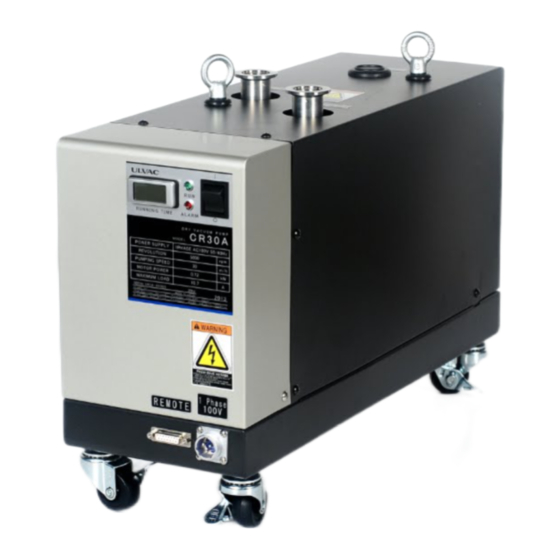
YK16-0010-DI-002-02 2.6 各部の名称と説明 図 3 各部名称 吸気口:真空排気する容器や配管に接続します。 排気口:排気されたガスの出口です。 ガスバラストガス :水分を含むガスを吸引する際に大気またはCDA ・N ガスを 2 導入するために使用します。 オプション品を準備しております。 *CDA:Clean Dry Air(乾燥空気) アジャスター:ポンプの固定に使用します。ジャッキアップは10mm以下。 ON/OFFスイッチ:ポンプの運転/停止に使用します。 運転ランプ:ポンプ運転中に点灯します。 アラームランプ:ポンプが異常時に点灯します。 積算運転時間計:運転の積算時間を表示します。 電源コネクタ:給電用のメタルコネクタです。 リモートコネクタ:リモート信号用の15ピンD-subコネクタです。 電源コネクタ用ガード:電源コネクタのガードに使用します。この製品は、承認済みの常時接続 装置であるため、電気配線接続後はガードを取り付ける必要がありあます。... -
Page 23: 3. 取付け
YK16-0010-DI-002-02 3. 取付け ①本製品を取り扱うには、ご使用になられる国や地域の安全に関する規則や 法令(例えば消防法、電気配線規定など)に従って設置および運用をしてく ださい。従ってご使用になられる国や地域で公的に有効とされている一般的 な安全教育(電気安全、荷役安全など)を受講する必要があります。安全教 育を受けていない方は、絶対に取り扱わないでください。 オペレーターは、それらのトレーニングを受けている必要があります。 警 告 また、電気、機械、荷役、真空などに関する専門知識および技能、資格が必 要です。 ②設置および取り外し作業を行う前に、すべてのエネルギー源(電気など)から 製品を分離してください。 3.1 据付 1) 据付は、粉塵がない、かつ湿気の少ない屋内の換気されている部屋にポンプを水平に設置して下さい。 周囲条件については「0.5.3 保管、据付および運転時の周囲条件」を参照下さい。 2) ポンプを設置する場所を決定します。 「2.5 外観寸法図」を参照下さい。電気配線をするために、周 囲には、ある程度スペースを確保して下さい。 3) オペレーターがポンプのON/OFFスイッチの入切が簡単に出来るように据え付けて下さい。 4) 吸込側と排出側のポートは、保護蓋でシールされています。ポンプを使用する準備が整うまで、蓋を取 り外さないでください。 5) 本機は空冷式です。機器の筐体内等で使用する場合は、充分な換気を行って下さい。 本機は空冷式です。設置時にキャスターを取り外し、直接地面に設置しない で下さい。ポンプ下部にある換気口が塞がれ、異常過熱による火傷、火災の 警 告 恐れがあります。 ポンプを衝撃を与えたり、傾けたり、横倒しにしたり、立てたり、逆さまにしない で下さい。ポンプの運転に障害を与えます。吸気口を上にして、ポンプを水平 注... -
Page 24: 3.2 配管の接続
YK16-0010-DI-002-02 3.2 配管の接続 3.2.1 吸気口側 A) 吸込口の保護蓋を取外し、KF用Oリングとクランプを使用し、配管を接続して下さい。 B) 吸気側配管は、コンダクタンスを充分考慮し設計して下さい。 真空室、配管、真空バルブ等の内側は、十分に洗浄してからポンプに接続してください。汚れた状 態で接続しますと、到達圧力が高くなったり、 所定の圧力まで減圧する時間が長くなったりします。 真空となる部分には、手袋をして、素手では触れないでください。 D) 吸気側配管と装置の総リーク量が、出来る限り小さくなるように必ずリークテストを行って下さい。 (但し、ポンプには、50kPaG 以上の圧力は掛けないで下さい。) E) 本機の振動は、充分小さくしておりますが、振動を嫌う装置の場合には、吸気側配管に伸縮継手 を挿入して下さい。 F) ポンプ停止により、大気が装置側へ逆流することを防止するために、装置とポンプの間に遮断弁 (メインバルブ)を設けて下さい。(図 4参照) G) ポンプ停止時に内部を乾燥、又はポンプ内部のガスを空気と置換する必要がある場合には、大 気開放弁を遮断弁(メインバルブ)とポンプ間に設けて下さい。(図 4参照) ①ポンプは、塵埃、細粉等の固体や水分を吸引しますと、到達圧力が悪くなる だけでなく故障の原因になることがあります。 ②吸気口に付けてある金綱は、ポンプユニット内にボルトなど大きな異物が入 るのを防ぐために取り付けてあります。点検等の必要がない限り外さないで 下さい。万が一、ポンプの吸気口内に異物(例えばボルト)を脱落させた場合 や、異物(例えば金網より細かな粉体や固形物)が吸引された場合は、ポン 注 意 プを分解して取り除く必要がありますので、近くのサービスセンターへ連絡し てください。そのまま運転すると、ポンプが停止することがあります。 ③O リングのシート面を傷つけないよう注意してください。配管の組立後、シス テム全体のリークテストを行ってください。(但し、ポンプには、50kPaG 以上... -
Page 25: 3.2.2 排気口側
YK16-0010-DI-002-02 3.2.2 排気口側 排気口フランジから保護蓋を取外して下さい。本機の最大排気口圧力は、大気圧です。ポンプに過 大な背圧が掛かると故障の原因になります。排気側配管にバルブ類がある場合は、全開として下さい。 吸引するガスに空気以外のガスが含まれる場合は、必ずポンプの排気口から排気ダクト等に接続し、 ポンプ周囲の環境を保全して下さい。 排気口側に配管する際、配管の口径が小さかったり、配管の内部に異物の付 着等があったりするとポンプの内部圧力が上昇します。その結果、ケーシング 注 意 やオイルレベルゲージが破裂したり、油漏れを起きたり、電動機の過負荷が発 生する恐れがあります。 ①ダクト配管を行う場合には、必ず導電性材料(電気を通すもの)を用いてくだ さい。非導電性材料を用いた場合、排気ガス通過時に静電気が発生し、帯 電してスパーク(火花)が発生し、発火元になることがあります。 ②可燃性ガス・支燃性ガスを流すプロセスの場合、希釈ガスを導入願います。 排気するガスの濃度が、爆発限界よりも低くなるよう吸気側から希釈ガスを 注 意 流してください。 ③排気配管が薄い金属配管、ジャバラ、ベロー等の場合、排気脈動で配管が 共振し、騒音が作業環境基準値を超えることがあります。十分耐圧がある配 管を使用してください。 図 4 基本的な配管接続図... -
Page 26: 3.2.3 ガスバラストガス
YK16-0010-DI-002-02 3.2.3 ガスバラストガス 本ポンプにはガスバラストガス導入機構が設けてあります。取扱いガスが凝縮性のガス、水分を含 む場合はポンプ最終段に液体が溜まる可能性があります。これを防ぐ為に、大気をポンプ最終段に導 入するか、N をポンプ最終段に導入することが出来ます。これによりポンプ最終段に液体が溜まるの 2 を防ぎます。 ①処理を行う際には、処理前の暖機運転、停止時の脱ガス運転(大気開放状 態での運転)を必ず行ってください。起動初期にポンプ本体の昇温が不十分 な状態での処理や、停止時に残留ガスがあると凝縮性ガスがポンプ内部で 凝縮し、ポンプの寿命を縮める要因となります。 ②排気側配管はL型配管等で横に曲げ、凝縮したガスがポンプに直接戻らな い構成として下さい。また、消音器等を取り付ける場合、消音器等で凝縮し ポンプに戻り破損を招く可能性があります。溜まった液体を排出する機構を 注 意 設けることを推奨します。 ③間欠運転等は行わずに、ポンプを停止させない運用を推奨します。 ④処理能力以上の水蒸気を排気した場合、ガスバラストガスを使用してもポン プ内部に凝縮し、ポンプの寿命を縮める可能性があります。 CR60B:500g/hr を目安にして下さい。 標準仕様では、工場出荷時にはガスバラストガスポートは封止されています。ガスバラストガス仕様 として下記オプションを準備しておりますので、用途に合わせてご注文時にご指定下さい。(表 2 型 式一覧表参照) 標準:エアーフィルター付属 プラグを外し、エアーフィルターを取り付けて下さい。 図 5 エアーフィルター取付図... -
Page 27: 図 6 ガスバラオプション: 手動1個(ニードルバルブ)説明図
YK16-0010-DI-002-02 ガスバラオプション:手動1個(ニードルバルブ)付き 図 6 ガスバラオプション: 手動1個(ニードルバルブ)説明図 ガスバラオプション:電磁弁+手動(ニードルバルブ)付き 図 7 ガスバラオプション:電磁弁+手動(ニードルバルブ) 説明図 DC24V駆動のNC(ノーマルクローズ)の 電磁弁が付属するオプションです。下記仕様を参照し配線す る事で、遠隔での開閉が可能となります。 消費電力:5.2/3.8 W (50/60Hz) 図 8 電磁弁配線方法説明図... -
Page 28: パージガス配管 推奨システム
YK16-0010-DI-002-02 N パージが必要な場合はガスバラストガス導入口のプラグを取り外し、R1/4のチューブ継手を取付 2 けてください。チューブ継手に1/4インチまたは6㎜以上のチューブ接続してください。 の供給圧力は 50 kPaG 以下、流量は 10 ~ 20 SLM としてください。 N 2 図 9 N パージガス配管 推奨システム ①窒素ガスの供給圧力を調整する減圧弁及び、供給を止める供給バルブを付 けて下さい。 注 意 ①窒素ガス配管を取り外す前に、窒素ガスの供給バルブを閉めてください。... -
Page 29: 3.3 電気配線
YK16-0010-DI-002-02 3.3 電気配線 ご使用になられる国や地域の安全に関する規則や法令(例えば消防法、電気 警 告 配線規定など)に従って設置および運用をしてください。 ①電気結線を行う時は、一次側の MCCB(配線保護用遮断器)のスイッチを切 ってから作業を行って下さい。 電圧をかけたままの作業は、絶対に行わないで下さい。 ②アースを確実に接地して下さい。故障や漏電のときに感電するおそれがあり 警 告 ます。 ③定格電圧以外で使用しないで下さい。過負荷保護装置が正常に作動せず、 焼損、火災の原因となります。 3.3.1 電源用配線 A) 本機の電源仕様は単相200-240V 50/60Hz または三相200-240V 50/60Hz です。電源仕様は 電源コネクタ付近に表示されています。 B) 電源容量は2.0kVA以上を準備して下さい。本機には動力を遮断する機構を装備しておりません。 下表の通りの定格電流のMCCB(配線保護用遮断器)を必ず設置して下さい。 表 4 電源容量及び推奨ブレーカ定格一覧 ポンプ型式-呼称 CR60B-T CR60B-S 電源電圧 三相 200-240V 単相 200-240V 電源容量... -
Page 30: 図 10 ガード取付け図
YK16-0010-DI-002-02 C) 電源接続コネクタのプラグ部に電源ケーブルを下表の通りハンダ付けして下さい。また電線サイ ズが適合電線サイズである事を確認して下さい。 ポンプ型式-呼称 CR60B-T CR60B-S X R L Y S N Z T G GND(アース) GND(アース) 表 5 コネクタ仕様一覧表 ポンプ型式-呼称 CR60B-T CR60B-S コネクタメーカ 株式会社七星科学研究所 レセプタクル型式 NET244-RM NET243-RM 適合プラグ型式 NET244-PF NET243-PF AWG#14 AWG#12 適合電線サイズ 2 2 (2.0mm ) (3.5mm )... -
Page 31: 3.3.2 リモート用配線
YK16-0010-DI-002-02 3.3.2 リモート用配線 ピンアサイン I/O 項目 仕様 1 N.C 2 N.C 3 N.C 4 N.C 5 OUT 起動確認 CLOSE:運転中 OPEN:停止中 6 OUT OUT COM 7 IN ポンプ起動 CLOSE:運転 OPEN:停止 8 IN IN COM 9 N.C 10 N.C 11 N.C 12 N.C... -
Page 32: 4.運転
YK16-0010-DI-002-02 4.運転 4.1 運転前の点検 1) 排気側配管系にバルブがある場合には、必ずバルブを全開として下さい。 2) メインバルブが円滑に動作するかを確認し、メインバルブを全閉として下さい。 3) 以上の点検・準備が終了したら、【表 6 】に示す起動前チェックリストを使用して再確認して下さい。 表 6 起動前チェックリスト Step 項目 確認 1 据付・配管は、確実に行われているか 2 電源電圧仕様は間違いないか 3 排気側配管のバルブは全開か 4 吸気側メインバルブは全閉か ①配管及び配線接続が完了している事を確認してください。 ②排気口を塞ぐなど排気口側にガスの通過を妨害する機器をつけた状態で真 空ポンプを運転しないで下さい。真空ポンプ内圧が上昇して、ケーシングや オイルレベルゲージが破裂・油漏れ、電動機の過負荷が発生する恐れがあ 警 告 ります。 ③排気口より後段の配管にバルブが付いている場合は、バルブが開いている ことを確認してください。 不活性ガス以外の有毒および可燃性・支燃性ガスを、真空ポンプで排気する 危 険 と、ポンプ本体から漏れることがありますので、使用することは出来ません。 不活性ガス以外の可燃性・支燃性ガス及び物質を、真空ポンプで排気すると、 真空ポンプ内部で発火・爆発することがありますので、使用することはできませ... -
Page 33: 4.2起動
YK16-0010-DI-002-02 4.2起動 部品寿命が短くなる可能性がありますので、一次側供給電源の投入/遮断で 警 告 の起動/停止は行わないでください。 運転前の点検が完了したら、以下の手順に従ってポンプを起動します。 4.2.1 ローカル運転 ローカル運転時には、付属のリモートコネクタのプラグを取付けた状態で御使用下さい。 1) 一次側のMCCB(配線保護用遮断器)を「ON」にして電源を投入してください。換気ファンが起動 します。 ON/OFFスイッチを「ON」にして下さい。運転ランプが点灯し、ポンプが徐々に回転を上げ、約15 秒以内に定常回転となります。 4.2.2 リモート運転 1) 一次側のMCCB(配線保護用遮断器)を「ON」にして電源を投入してください。換気ファンが起動 します。 2) ポンプのON/OFFスイッチを「ON」の状態にして下さい。 リモートコネクタに配線された遠方のスイッチを「ON」として下さい。運転ランプが点灯し、ポンプが 徐々に回転を上げ、約15秒以内に定常回転となります。 4.3 起動後の確認と調整 ポンプ起動後、以下の内容を確認して下さい。 1) 異常振動・騒音がないか確認して下さい。 2) 凝縮性ガスの排気を行なう場合は、暖気運転を行なって下さい。 3) N2パージする場合は、N2ガスを供給して下さい。 4) 徐々にメインバルブを開いて下さい。 起動手順 参照項目番 排気側配管系にバルブがある 4.1 運転前の点検 1) 場合には必ずバルブを全開とする... - Page 34 YK16-0010-DI-002-02 4.4 停止 ポンプを停止するには以下の手順に従って下さい。 1) 取扱いガスの逆流を防ぐ為に、メインバルブを閉として下さい。 2) ポンプ内部を乾燥、又はポンプ内部のガスを空気と置換する必要が在る場合には、大気開放弁 を開放し、約3~5分間運転を行なって下さい。 3) ローカル運転時には、ON/OFFスイッチを押して下さい。リモート運転の場合は遠方のスイッチを 「OFF」にして下さい。ポンプが停止し、運転ランプが消灯します。 4) 一次側のMCCB(配線保護用遮断器)を「OFF」にして下さい。換気ファンが停止します。 停止手順 参照項目番号 4.4 停止 メインバルブ:閉 4.4 停止 大気開放弁:開 4.4 停止 乾燥運転実施 4.4 停止 ON/OFF スイッチ:OFF (遠方のスイッチ:OFF) 4.4 停止 電源遮断 ポンプが異常停止した場合は、安全の為に原因を取り除いてからポンプを再起動させて下さい。 ①運転停止後のしばらくは、真空ポンプやモータ、配管は非常に高温になりま すのでパネルを外したりして触れないでください。人体に接触すると火傷の危 険があります。 警 告 ②ポンプを長時間停止する際は、必ずブレーカを切り、電源を断って下さい。...
-
Page 35: 図 12 排気速度曲線図
YK16-0010-DI-002-02 5.ポンプの性能 CR60 1000 10000 100000 Pressure [Pa] 図 12 排気速度曲線図 1400 1200 CR60 1000 1000 10000 100000 Pressure [Pa] 図 13 電力値曲線図... - Page 36 YK16-0010-DI-002-02 6. 取り外し 6.1 電気結線 ご使用になられる国や地域の安全に関する規則や法令(例えば消防法、電気 警 告 配線規定など)に従って設置および運用をしてください。 1) 一次側のMCCB(配線保護用遮断器)をマニュアルに従いロックアウト及びタグアウトして下さい。 2) 一次側の2次側通電表示ランプにて通電されていない事を確認するか、テスター等を用いて通電 されていない事を確認して下さい。 3) 電源コネクタを外して、ポンプを電源から切り離して下さい。 取り外し作業を行う前には、確実に電源から切り離してください。 警 告 6.2 吸排気口配管 ①装置の設置マニュアルに従って、取り外してください。 ②運転停止後のしばらくは、吸排気口配管は非常に高温になりますので触れ 警 告 ないでください。ポンプの温度が下がってから取り外しを行って下さい。 ③ポンプの吸排気口を閉止フランジなどで完全に密閉してください。 6.3 窒素ガス配管(接続されている場合のみ) ①窒素ガス配管を取り外す前に、窒素ガスの供給バルブを閉めてください。 ②装置側の配管には残圧が残ります。装置の窒素供給源(ポンプまでの配管 警 告 の途中)に圧力計を設置し、圧力が大気圧まで低下したことを確認してから 窒素ガス配管を取り外してください。作業を行う時、内圧が高い状態の場合、 配管が勢いよくはずれ、怪我をする可能性があります。 ガスバラストガス導入口より、窒素ガス配管を取り外して下さい。...
-
Page 37: 表 7 点検項目表
YK16-0010-DI-002-02 7. 保守 7.1 点検 良好な運転状態を保つために下表に示す点検・保守を実施下さい。 表 7 点検項目表 点検周期 点検項目 ポンプ運転音の確認 (異常音の有無確認) 毎日点検 吸込圧力及び吐出圧力の確認 運転動力の確認 毎月点検 吸込口のストレーナの清掃 表 7に示す点検周期は標準的な周期の目安として下さい。取扱いガス、ポンプ運転時間、ポンプ起 動停止の頻度に応じて適切な時期に点検を実施して下さい。 7.2 長期保管後の運転 長期間保管(6ヶ月以上)後、または装置の長期停止(6ヶ月以上)後、使用すると、運転時に内部部 品が破損する恐れがありますので、長期間使用しなかった場合は点検を最寄りのサービスセンターに ご依頼ください。 7.3 オーバーホール オーバーホールは2年に1度行なって下さい。なお、使用条件によりポンプの汚染や性能悪化が著し い場合は、2年以内でもオーバーホールを行って下さい。到達圧力付近での連続運転(粉体、湿気、腐 食要素の吸引なし)条件に於いて、目安として2年に1回の推奨となります。(但し交換対象部品は使用 環境により交換時期が異なります。) オーバーホールは性能(安全も含む)を維持するために、また、計画的な生産を継続するためにも必 要です。 オーバーホールは、最寄りのサービスセンターにお問い合わせ下さい。なお、オーバーホール依頼時 には、巻末にある汚染証明書を必ず記入してご提出下さい。 ご使用の危険物質の詳細を開示いただけない場合や、無害化処理が困難な物 質を排気した場合には、弊社でのメンテナンスその他の取扱いをお断りするこ 警 告 とがあります。... -
Page 38: 表 8 トラブルチェックリスト
電源を入れて下さい 正しく配線する(3.3.1 電源用配 電源コネクタの配線間違い 線参照) ON/OFF スイッチを ON したが、 電源電圧が低い 電圧測定の実施 ポンプが起動しない 付属のリモートコネクタが正しく配線 正しく配線する(3.3.2 リモート用 されていない 配線参照) サービスセンターへ連絡 ポンプ内部での漏電 →ULVAC 技術員修理 ON/OFF スイッチが入っていない ON/OFF スイッチを ON にする 遠隔操作でポンプが起動しない サービスセンターへ連絡 計装品の故障 →ULVAC 技術員修理 吐出側の閉塞、バルブのつまり 吐出側配管系の点検 換気口出入口の閉塞がないか確認 周囲環境温度の確認(0.5.3 保 管、据付および運転時の周囲条件参 ポンプ周囲の換気不良による温度異 照)... - Page 39 YK16-0010-DI-002-02 8. 廃棄 真空ポンプを廃棄するときは、法律および地方自治体の定める条例に従って処理して下さい。特に、 有害ガスを排気した場合には、専門の処理業者に廃棄処理を委託して下さい。 なお、廃棄に関する費用については、お客様にてご負担をお願いします。 ①人体に危険を及ぼす有害ガスを排気した場合には、専門の処理業者に廃棄 処理を委託して下さい。ポンプ本体のみならず、潤滑油も有害になります。 警 告 ②処理は、化学物質安全性データシートの『廃棄上の注意』欄に従って処理し て下さい。 9. 保証条項 本製品は、厳格な社内検査を経て出荷されておりますが、万一製造上の不備、輸送中の事故など、弊 社の責による故障が発生した場合には、最寄りの営業所または代理店に申しつけ下さい。 無償にて修 理・交換致します。 9.1 保証対象 多段ルーツ式ドライポンプ CR60B 9.2 保証期間 1) 日本国内取引の場合:弊社出荷日より 1 年間 2) 直接輸出取引の場合:B/L 日付より1年間 9.3 保証範囲 1)保証範囲と免責事項 保証範囲は、ポンプのみとします。空気または、窒素の排気において、弊社の設計, 製作上の不 備により故障及び事故が発生した場合、納入後1年以内については、無償にて修理致します。 また以下による故障の場合は、保証範囲外となり保証期間内でも有償修理となります。 ・空気または窒素以外のガスまたは物質を排気しての故障、不具合 ・消耗品に起因する故障、不具合 ・ご注文時のご指定の電源電圧・周波数と異なる電源で使用した場合...
- Page 40 YK16-0010-DI-002-02 9.4 対応方法 1) 日本国内取引の場合: 代替品の送付 もしくは 弊社又は最寄りのアルバックテクノへ返送頂き修理を実施します。現地対 応が必要な場合は別途最寄りの営業所または代理店にご相談下さい。 2) 直接輸出取引の場合: 代替品の送付 もしくは 弊社又は最寄りの弊社サービスセンターへ返送頂き修理を実施します。返 送費用は、お客様にてご負担願います。 9.5 その他 1) 本書類とは別に個別契約書や仕様に関する覚書などが存在する場合は、その記載内容に準じま す。 2) 本製品を日本国外に輸出する場合には弊社宛てに一報頂きますと共に、外国為替及び外国貿易 法等輸出関連法規の規定に従って必要な手続きをお取り下さいますようお願い致します。 3) 本製品についての質問や相談に関しては、型式・製造番号をお確かめの上、最寄りの営業所また は代理店にご連絡ください。 http://www.ulvac.co.jp/support_info 4) 本書の内容は、予告なしに変更する場合があります。ご了承下さい。...
- Page 41 様式番号:A003S1268-03 アルバック コンポーネント 汚染証明書 本紙はアルバック製コンポーネントの返却を行なう際の汚染証明書となります。 弊社に貴社保有の機器のお送りいただく前に、 本書をご記入の上、 作業依頼先又は各担当営業所にご提出願います。 。 尚、有毒ガス使用品・反応生成物質付着品に付きましては事前に作業依頼先又は各担当営業所までお問合せ願います 商品名 : 型式 : : 用途 : 依頼内容 (返却理由、使 用状況、特記事 項など) 汚染物質(□部の該当箇所にチェックをお願いします。 ) □ 上記製品は、有害物質によって汚染されてないことを保証します。 □ 上記製品は、以下の有害物質によって汚染されています。 汚染物質名(分子式) 特性 1 2 3 4 5 株式会社アルバック 行 貴社の窓口となった担当者名 年 月 日 御客様・会社名...
-
Page 43: Instruction Manual
YK16-0010-DI-002-02 Original instructions INSTRUCTION MANUAL DRY VACUUM PUMP Model CR60B Before using this product, be sure to read this operation manual. Keep this manual with care to use at any time. ULVAC, Inc. Components Division http://www.ulvac.co.jp/... - Page 45 Declaration of Conformity...
-
Page 46: Before Using This Product
The performance and safety of the product might not be ensured if any of the devices put together did not conform to same regulations or the product itself was modified. ULVAC shall be not liable to guarantee performance and safety in such cases above. Any modification of the product by the user is out of the scope of guarantee by us and not be guaranteed in any manner. -
Page 47: Safety Symbol Marks
YK16-0010-DI-002-02 0.1 Safety Symbol Marks We display symbol marks regarding the safety in this manual and on the product to make clear items to observe. Descriptions attached to the symbol are classified as illustrated below; 0.2 Meanings of Safety Symbol Marks If the user makes a mistake in handling, it indicates an imminent possibility that the user is subject to death or heavy injury. -
Page 48: Safety Precautions
YK16-0010-DI-002-02 0.3 Safety Precautions Descriptions are given as the method to keep away from danger and actions that must be restricted on the use of the product. Use of this product and this instruction manual. Please read this Instruction Manual before starting installation, operation check or maintenance of this product to use it in long term. - Page 49 YK16-0010-DI-002-02 Installation and storage (1) Do not push the Pump over sideways because it is shipped with lubrication oil filled up. (2) Give the instruction them further to use the unloading machinery such as crane to take out the product of the cardboard, lift it up with its top eyebolt and transfer it on lifting.
- Page 50 YK16-0010-DI-002-02 Inlet piping <Mounting> Check and ensure that any of hazardous energy is blocked before starting the operation. WARNING Power Supply wiring <Mounting> (1) Check and ensure that any of hazardous energy is blocked before starting the operation. (2) Entitled staff should conduct the wiring operation. Erroneous wiring work might cause a fire.
- Page 51 YK16-0010-DI-002-02 Shutdown Do not touch, open the pump cover because the motor, pump or pipe is and remains very hot while after having stopped operation. You have a risk of getting burned if a part of the body touched it. WARNING Check and repair (1) Be sure to turn OFF the MCCB (Molded Case Circuit Breaker) primary side...
-
Page 52: Types And Descriptions Of Warning Labels Displayed On This Pump And Displayed Positions
YK16-0010-DI-002-02 0.4 Types and Descriptions of Warning Labels Displayed on this Pump and Displayed Positions Warning labels are attached on the warning locations in this Pump. Be sure to check them before starting operation of the Pump. There is a risk of getting electrical shock around the section that this warning label is put. -
Page 53: Acceptance And Storage Of The Pump
YK16-0010-DI-002-02 0.5 Acceptance and Storage of the Pump 0.5.1 Unpacking/Acceptance of the Pump (1) Do not push the Pump over sideways because it is shipped with lubrication oil filled up. (2) Give the instruction them further to use the unloading machinery such as crane to take out the product of the cardboard, lift it up with its top eyebolt and transfer it on lifting. -
Page 54: Transfer
YK16-0010-DI-002-02 0.5.2 Transfer (1) Although this pump is provided with casters, do not move it a long distance using these casters. (2) Weight of this product is as follows. CR 60 : 48 kg You have a risk of giving damage to your back as the load larger than WARNING safety standard shall be required to transfer the product. - Page 55 YK16-0010-DI-002-02 Table of Contents INSTRUCTION MANUAL ........................1 0. Before Using This Product .......................... i 0.1 Safety Symbol Marks ........................... ii 0.2 Meanings of Safety Symbol Marks ...................... ii 0.3 Safety Precautions..........................iii 0.4 Types and Descriptions of Warning Labels Displayed on this Pump and Displayed Positions..vii 0.5 Acceptance and Storage of the Pump ....................
- Page 56 8. Disposal ..............................24 9. Warranty Clauses ........................... 24 9.1 Warrantable Items..........................24 9.2 Warranty period ..........................24 9.3 Warrantee scope ..........................24 9.4 Response procedure ........................25 9.5 Others ............................... 25 Request Form for Repair/Inspection of ULVAC Components /Certificate of Contamination Contents-2...
- Page 57 YK16-0010-DI-002-02 Tables and Illustrations Fig. 1 Vacuum mechanism map ......................4 Fig. 2 CR60B Outline dimensional drawing ..................6 Fig. 3 Name of each part ........................7 Fig. 4 Typical pump layout........................10 Fig. 5 Installation drawings of air filter ....................11 Fig.
-
Page 58: For Your Safety Use
YK16-0010-DI-002-02 1. For Your Safety Use 1.1 This Product Intrinsic Hazardous Nature and Safety Measures 1.1.1 Danger Leakage of dangerous gas and dangerous materials Factors Avoidance methods and measures Exhaust gas such has toxic and combustible, burnability, corrosion, explosiveness very danger. -
Page 59: Warning Electric Shock
YK16-0010-DI-002-02 1.1.3 Warning Electric shock Factors Avoidance methods and measures (1) Be sure to cut the electricity to do electrical connection. Never fail to take the grounding. (2) Ensure to close the cover of motor terminal box and never open it during operation. Getting electrical shock on touching (3) Be sure to cut the electricity to do checking or the current-carrying. -
Page 60: Chemical Material Safety Data Sheet(Sds
YK16-0010-DI-002-02 1.2 Chemical Material Safety Data Sheet(SDS) Chemical material used for this Pump; Pump oil: BARRIERTA J100 FLUIDE E (NOK KLUBER) The Safety Data Sheet introduces the chemical material potential to use or IMPORTANT touch on operating this machine. Please contact our Sales division if you are in need. -
Page 61: Pump Outline
YK16-0010-DI-002-02 2. Pump Outline 2.1 Features High Reliability: Long-term continuous operation is possible as there are no sliding parts. Forced air-cooled: Can be placed anywhere because cooling water is not required. It is low running cost. Lightweight, compact: Easy to move because of lightweight and it is equipped with casters. Clean vacuum and evacuation: Dry pump without any sliding parts. -
Page 62: Performance Specifications
YK16-0010-DI-002-02 Table. 2 Details model list Model Rev. Naming External option CR60 ① ② ①Gas ballast Rev. Non : With air filter(Standard) B : Current Rev. : 1 manual valve(Needle valve) : Solenoid valve + manual valve Naming Shows power specifications (Needle valve) Single phase : S ②Rubber feet... -
Page 63: Outline Dimensional Drawing
YK16-0010-DI-002-02 2.5 Outline dimensional drawing Fig. 2 CR60B Outline dimensional drawing... -
Page 64: Name And Description Of Each Part
YK16-0010-DI-002-02 2.6 Name and description of each part Fig. 3 Name of each part Inlet flange : To be connected to vacuum chamber or pipe. Outlet flange : Outlet of exhaust gas. Gas ballast gas port : To be used to introduce air or CDA*, N2 gas if intake gas contains moisture. -
Page 65: Mounting
YK16-0010-DI-002-02 3. Mounting (1) You are requested to install and operate the product in compliance with the laws and regulations relating to the safety, e.g. Fire Defense Law, Electric wiring regulation and so on in the country and region you use the product. -
Page 66: Piping
YK16-0010-DI-002-02 3.2 Piping 3.2.1 Piping for inlet side Connect for pipe with KF type O-ring and cramp after removing inlet flange cap. Design the inlet side pipe with enough consideration to conductance. Connect the vacuum chamber, pipe and valve after washing inside them thoroughly. Time to reach to ultimate pressure could be longer or ultimate pressure could be worse if connected with being contaminated. -
Page 67: Piping For Exhaust Side
YK16-0010-DI-002-02 3.2.2 Piping for exhaust side Remove cap from outlet flange. Maximum outlet pressure of this pump is atmosphere pressure. Excessive pressure exerted on the pump causes failure. Open full of the valve if valve is installed in the exhaust side Connect to the exhaust duct from the outlet of the pump if intake gas contains moisture. -
Page 68: Gas Ballast Valve
YK16-0010-DI-002-02 3.2.3 Gas ballast valve This product has the gas ballast function as standard. Condensed gas shall be liquefied at the final stage if intake gas contains moisture. Air or N2 can be introduced to the final stage, in order to prevent this. - Page 69 YK16-0010-DI-002-02 Gas ballast option code: 1 manual valve (Needle valve) and air filter Fig. 6 Explanatory diagram of gas ballast option : 1 manual valve Gas ballast option code: Solenoid valve + manual valve (Needle valve) and air filter Fig. 7 Explanatory diagram of gas ballast option: Solenoid valve + manual valve...
- Page 70 YK16-0010-DI-002-02 It is an option NC (Normally closed) type solenoid valve driven by DC24V. Will become possibility to remotely open and close, by wiring refer to the following specifications. Fig. 8 Explanatory diagram of method for solenoid valve wiring Install R1/4 tube fittings by removing plug of gas ballast gas port, if N2 purge necessary. Connect to tube fitting the 1/4 inch tube.
-
Page 71: Electrical Connection
YK16-0010-DI-002-02 3.3 Electrical Connection Install and operate this pump in compliance with the laws and regulations relating to the safety, e.g. Fire Defense Law, Electric wiring regulation and so on. In the country and region you use the product. CAUTION (1) Turn OFF the Power Supply to do the electrical connection. - Page 72 YK16-0010-DI-002-02 Solder power supply cable to plug of power connection connector as shown in the table below. Make sure wire size is applicable wire size. Pump model- CR60B-T CR60B-S R phase L phase S phase N phase T phase PE/GND PE/GND Table.
-
Page 73: Wiring For Remote Control
YK16-0010-DI-002-02 3.3.2 Wiring for remote control Pin assignment No. I/O Item Specification OUT Start check CLOSE:Running OPEN:At stop OUT OUT COM Pump start CLOSE:Run OPEN:Stop IN COM 13 OUT Alarm CLOSE:Normal OPEN:Alarm Alarm reset CLOSE:Reset Specifications Connector maker Dai-ichi Denshi Ind., Ltd. Connector part No. -
Page 74: Operation
YK16-0010-DI-002-02 4. Operation 4.1 Check points and Preparations before Operation The valve in the outlet side piping line should be fully opened. 2) The main valve should be operated smoothly. After checking the valve operation, the main valve should be fully closed. 3) Confirm the conditions once again in accordance with the pre-starting check points of Table. -
Page 75: Local Operation
YK16-0010-DI-002-02 After completion of the check points and preparations before operation, start the pump according to the following procedure. 4.2.1 Local operation During local operation, keep the remote connector plug delivered with the Pump being connected. 1) Supply power by turning on primary side MCCB (Molded Case Circuit Breaker). Then cooling fan starts. -
Page 76: Operation Stop
YK16-0010-DI-002-02 4.4 Operation Stop Follow these steps to stop the pump. 1) In order to prevent the back (reverse) flow of the atmospheric air or the handling gas, fully close the main (isolation) valve at suction piping side. 2) If the handling gas contains condensable gas or water vapor, the pump inside has to be dried. -
Page 77: Pump Performance
YK16-0010-DI-002-02 5. Pump Performance CR60 1000 10000 100000 Pressure [Pa] Fig. 12 Pumping speed curves 1400 1200 CR60 1000 1000 10000 100000 Pressure [Pa] Fig. 13 Power-Pressure curves... -
Page 78: Dismantling
YK16-0010-DI-002-02 6. Dismantling 6.1 Power Supply Wiring Install and operate the product in compliance with the laws and regulations relating to the safety, e.g. Fire Defense Law, Electric wiring regulation and so on. In the country and region you use the product. CAUTION 1) Make lockout and tag-out according to the instruction manual of MCCB (Molded Case Circuit Breaker). -
Page 79: Maintenance
YK16-0010-DI-002-02 7. Maintenance 7.1 Check Be sure to check and maintenance shown in the table below, for maintain good running condition. Table. 7 Checking item list Checking cycle Checking item Check the running sound of the pump. (Check the Daily check presence of abnormal sound) Check suction and outlet pressure. -
Page 80: Trouble Shooting
(Refer to 3.3.2 Wiring for remote wired incorrectly. control) Contact service center. To be repaired Electric leak in the pump. by ULVAC. ON/OFF switch is not turned on. Turned on the ON/OFF switch. Pump does not start by Contact service center. To be repaired remote operation. -
Page 81: Disposal
(1) Scope and exclusion of warranty The scope of warranty is limited to the Pump only. ULVAC will repair this pump free of charge for a period of twelve (12) months from the date of delivery in case it failed due to defects in design or manufacturing during pumping down of air or nitrogen gas. -
Page 82: Response Procedure
(1) In case, special agreement or memorandum for specifications is made individually, it comes in first. (2) Buyer shall inform ULVAC when this product is exported out of Japan. In the meantime, Buyer shall take necessary procedures according to Foreign Exchange and Foreign Trade Law. - Page 83 ULVAC service center or sales office prior to shipment. Please consult with your closest local ULVAC service center or sales office if our components are used with toxic gases or contaminated with reactive products or substances produced by reaction.
- Page 84 This mark is applied to the electronic information product sold in the People's Republic of China. The figure at the center of the mark is the validity date of environmental protection. This product does not influence the environment, the human body and the property during the period reckoning the manufacturing date as long as the caution for safe use regarding the products are observed.
Need help?
Do you have a question about the CR16B and is the answer not in the manual?
Questions and answers