Table of Contents
Advertisement
Quick Links
DEMO_FX3_LVDS_CAM01 EZ-USB™ FX3
BT.1120/LVDS camera interface kit guide
About this document
Scope and purpose
This document is a user guide for the DEMO_FX3_LVDS_CAM01 EZ-USB™ FX3 BT.1120/LVDS camera interface
kit. This kit enables you to stream USB Video Class (UVC) and USB3 Vision (U3V) 1080p videos at 60fps from the
block cameras to a PC using BT.1120 or LVDS protocols. Refer to the relevant sections based on your
requirement:
Introduction
– Provides basic information on the kit
•
Installing the kit software
•
Kit hardware
– Explains the kit architecture and system design details
•
Kit programming
– Describes the procedure to program the kit
•
Kit operation
– Explains the procedure to operate the kit
•
Intended audience
This document is intended for the users of DEMO_FX3_LVDS_CAM01 EZ-USB™ FX3 BT.1120/LVDS camera
interface kit.
User guide
Please read the sections "Important notice" and "Warnings" at the end of this document
www.infineon.com
– Explains the installation of software required to program the kit
002-38028 Rev. *A
2023-11-23
Advertisement
Table of Contents

Related Manuals for Infineon FX3 EZ-USB DEMO_FX3_LVDS_CAM01


Summary of Contents for Infineon FX3 EZ-USB DEMO_FX3_LVDS_CAM01
- Page 1 – Explains the procedure to operate the kit • Intended audience This document is intended for the users of DEMO_FX3_LVDS_CAM01 EZ-USB™ FX3 BT.1120/LVDS camera interface kit. User guide Please read the sections “Important notice” and “Warnings” at the end of this document 002-38028 Rev. *A www.infineon.com 2023-11-23...
-
Page 2: Table Of Contents
DEMO_FX3_LVDS_CAM01 EZ-USB™ FX3 BT.1120/LVDS camera interface kit guide Table of contents Table of contents Table of contents ..........................2 Introduction .......................... 3 Kit contents ............................. 3 Download kit documents and hardware design files ................3 Board details ............................4 Kit features .............................. 4 Installing the kit software ....................... -
Page 3: Introduction
Introduction Introduction This kit is based on Infineon’s USB 5 Gbps controllers’ FX3 product family. FX3 has a fully programmable General Programmable Interface (GPIF II) that can interface with any processor, ASIC, image sensor, or FPGA. It provides easy and effortless connectivity to popular industry interfaces such as synchronous slave FIFO and image sensor interfaces. -
Page 4: Board Details
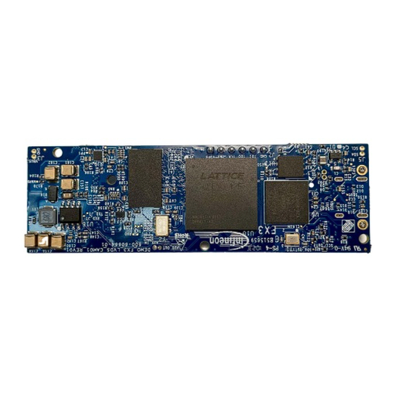
DEMO_FX3_LVDS_CAM01 EZ-USB™ FX3 BT.1120/LVDS camera interface kit guide Introduction Board details Figure 1 FX3 LVDS camera kit Kit features The kit features an FX3 controller and ECP5 FPGA from Lattice Semiconductor that can be configured to stream UVC and U3V video from block cameras into a PC. See Section 5 for more details. -
Page 5: Installing The Kit Software
Installing the kit software Installing the kit software Before you start The installation of the FX3 SDK and other Infineon software may require administrator privileges. However, privileges are not required to run the software once it is installed. Install FX3 SDK Download and install EZ-USB™... -
Page 6: System Design
DEMO_FX3_LVDS_CAM01 EZ-USB™ FX3 BT.1120/LVDS camera interface kit guide System design System design This kit is bus-powered. To demonstrate the full functionality of the kit, connect the block/bt.1120 camera module to the onboard Low Voltage Differential Signaling (LVDS) or FFC connectors respectively. Top-level hardware design Figure 2 FX3 LVDS camera kit architecture... -
Page 7: Power Supply
0.8-mm pitch, Pb-free ball grid array (BGA) package. 3.2.5 SPI flash (U11) The kit firmware is stored on an Infineon 64-Mbit SPI flash. After power-on, FX3 fetches the required details from the firmware image, stores it in its RAM, and starts executing from it. 3.2.6 LVDS camera coaxial connector (J6) The kit has an onboard 30-pin micro-coaxial connector to connect the LVDS block cameras. -
Page 8: Lattice Ecp5 Fpga (U10)
DEMO_FX3_LVDS_CAM01 EZ-USB™ FX3 BT.1120/LVDS camera interface kit guide System design 3.2.10 Lattice ECP5 FPGA (U10) The kit uses an ECP5 family FPGA from Lattice Semiconductor. It is a high-performance device with dedicated DDR3 RAM interfaces and supports high-speed signaling. This FPGA acts as a bridge between the block camera and the FX3 device. -
Page 9: Programming The Fx3 Camera Interface Kit
DEMO_FX3_LVDS_CAM01 EZ-USB™ FX3 BT.1120/LVDS camera interface kit guide Programming the FX3 LVDS camera kit Programming the FX3 LVDS camera kit The DEMO_FX3_LVDS_CAM01 kit is preprogrammed with the latest firmware to stream 1080p U3V videos at 60 fps from the BT.1120 block camera module provided with the kit. Use the USB Control Center application available in the FX3 SDK to change the firmware. - Page 10 DEMO_FX3_LVDS_CAM01 EZ-USB™ FX3 BT.1120/LVDS camera interface kit guide Programming the FX3 LVDS camera kit Figure 5 Device enumeration in control center application Click Program > FX3 > SPI FLASH Figure 6 Programming the SPI FLASH Browse to select the downloaded firmware file User guide 002-38028 Rev.
- Page 11 DEMO_FX3_LVDS_CAM01 EZ-USB™ FX3 BT.1120/LVDS camera interface kit guide Programming the FX3 LVDS camera kit Table 3 FW image file Mode Testing Module FW Image BT.1120 Block Camera Board FX3_MergedFirmware_BT1120_UVC.img LVDS Block Camera Board FX3_MergedFirmware_LVDS_UVC.img BT.1120 Block Camera Board FX3_MergedFirmware_BT1120_U3V.img LVDS Block Camera Board FX3_MergedFirmware_LVDS_U3V.img Wait for programing to complete.
-
Page 12: Kit Operation
DEMO_FX3_LVDS_CAM01 EZ-USB™ FX3 BT.1120/LVDS camera interface kit guide Kit operation Kit operation Important note: Before starting the demo, ensure the kit is loaded with the appropriate firmware as shown in Table Booting from the SPI flash Set the SW1 switch setting to SPI position as follows: Move SW1 pin 1 to ON position and pin 2 to OFF position. - Page 13 DEMO_FX3_LVDS_CAM01 EZ-USB™ FX3 BT.1120/LVDS camera interface kit guide Kit operation Open the eBUS Player app. Click Select/Connect from the eBUS Player. Verify that FX3 is detected as shown Figure Figure 9 Selecting USB3 Vision device in eBUS Player application If FX3 is not detected, go to C:\Program Files\Common Files\Pleora\eBUS SDK\U3V\Certified and install the U3V driver as shown in Figure Figure 10...
- Page 14 DEMO_FX3_LVDS_CAM01 EZ-USB™ FX3 BT.1120/LVDS camera interface kit guide Kit operation Click Play and observe the streaming video in the display pane. You can check the streaming statistics in the status pane below the display pane. It should display 60fps. Figure 11 Check the streaming video in the display pane and its statistics in the status pane Click Device control and verify the streaming resolution is set to 1920 x 1080, indicating 1080p streaming.
-
Page 15: Uvc Video Streaming From Bt.1120 Block Camera
DEMO_FX3_LVDS_CAM01 EZ-USB™ FX3 BT.1120/LVDS camera interface kit guide Kit operation UVC video streaming from BT.1120 block camera 1. Ensure that the steps in Section 4 are followed and the FX3_MergedFirmware_BT1120_UVC.img firmware image is loaded. 2. Ensure that the steps in Section 5.1 are followed to boot from SPI flash. - Page 16 DEMO_FX3_LVDS_CAM01 EZ-USB™ FX3 BT.1120/LVDS camera interface kit guide Kit operation Figure 14 Selecting USB3 Vision device in eBUS Player application Click Play and observe the streaming video in the display pane. You can check the streaming statistics in the status pane below the display pane. It should display 60fps. Figure 15 Check the streaming video in the display pane and its statistics in the status pane Click Device control and verify the streaming resolution is set to 1920 x 1080, indicating 1080p streaming.
-
Page 17: Uvc Video Streaming From Lvds Block Camera
DEMO_FX3_LVDS_CAM01 EZ-USB™ FX3 BT.1120/LVDS camera interface kit guide Kit operation Figure 16 Device control settings UVC video streaming from LVDS block camera 1. Ensure that the steps in are followed and SX3_MergedFirmware_LVDS_UVC.img firmware image is Section 4 loaded. 2. Ensure that the steps in are followed to boot from SPI flash. -
Page 18: Streaming Other Resolutions
DEMO_FX3_LVDS_CAM01 EZ-USB™ FX3 BT.1120/LVDS camera interface kit guide Kit operation Streaming other resolutions 1. This kit supports the following resolutions: Table 4 Supported resolutions by this kit Video Type Resolution (Width x Height) Frame Rate (fps) 1080p 1920 x 1080 720p 1280 x 720 2. - Page 19 DEMO_FX3_LVDS_CAM01 EZ-USB™ FX3 BT.1120/LVDS camera interface kit guide Kit operation Figure 19 Display resolution changed to 720p Click Play to stream the video. Figure 20 Video streaming at 720p User guide 002-38028 Rev. *A 2023-11-23...
-
Page 20: Changing Camera Parameters In Lvds Block Camera
DEMO_FX3_LVDS_CAM01 EZ-USB™ FX3 BT.1120/LVDS camera interface kit guide Kit operation Changing camera parameters in LVDS block camera Note: This kit supports modification of camera parameters only in the UVC streaming mode. However, it is also possible to implement this feature in the U3V mode. To change the camera parameters, the VISCA serial commands are sent over USB CDC class. - Page 21 DEMO_FX3_LVDS_CAM01 EZ-USB™ FX3 BT.1120/LVDS camera interface kit guide Kit operation Sony FCB Control software application Figure 22 You can control zoom, focus, AE mode brightness, and other parameters of the camera using the application. Streaming video Figure 23 User guide 002-38028 Rev.
-
Page 22: Troubleshooting
DEMO_FX3_LVDS_CAM01 EZ-USB™ FX3 BT.1120/LVDS camera interface kit guide Troubleshooting Troubleshooting Programming test 6.1.1 No bootloader device detected in USB Control Center If “Cypress FX3 USB Bootloader device” is not visible in the USB Control Center application, verify that the PMODE switch (SW1) is in the “USB” state. Figure 24 Mode switch setting for USB mode Video streaming test... -
Page 23: Re-Assigning The Com Port
DEMO_FX3_LVDS_CAM01 EZ-USB™ FX3 BT.1120/LVDS camera interface kit guide Troubleshooting Re-assigning the COM port Follow these steps to re-assign the COM port number: Select the COM port you want in order to change the COM port number Device manager Cameras and Ports with FX3 camera and COM ports Figure 26 Right-click on the COM port and select Properties Select COM port properties... - Page 24 DEMO_FX3_LVDS_CAM01 EZ-USB™ FX3 BT.1120/LVDS camera interface kit guide Troubleshooting Port Settings Figure 28 Select the COM port number less than 16 and click OK. Selecting COM port value less than 16 Figure 29 Disconnect and re-connect the USB cable, observe the COM port number (COM port number should be shown as assigned).
-
Page 25: References
DEMO_FX3_LVDS_CAM01 EZ-USB™ FX3 BT.1120/LVDS camera interface kit guide References References [1] Product webpage: EZ-USB™ FX3 webpage [2] Kit webpage: DEMO_FX3_LVDS_CAM01 webpage [3] Datasheets: EZ-USB™ FX3 datasheet User guide 002-38028 Rev. *A 2023-11-23... -
Page 26: Technical Support
DEMO_FX3_LVDS_CAM01 EZ-USB™ FX3 BT.1120/LVDS camera interface kit guide Technical support Technical support If you have any questions, create a support request on the Infineon Technical Support page. User guide 002-38028 Rev. *A 2023-11-23... -
Page 27: Revision History
DEMO_FX3_LVDS_CAM01 EZ-USB™ FX3 BT.1120/LVDS camera interface kit guide Revision history Revision history Document Date Description of changes revision 2023-06-28 Initial release 2023-11-23 Changed SuperSpeed references to USB 5 Gbps. Changed the document category to User Guides. User guide 002-38028 Rev. *A 2023-11-23... - Page 28 With respect to any examples, hints or any typical 81726 Munich, Germany values stated herein and/or any information WARNINGS regarding the application of the product, Infineon Technologies hereby disclaims any and all Due to technical requirements products may contain warranties and liabilities of any kind, including dangerous substances.
Need help?
Do you have a question about the FX3 EZ-USB DEMO_FX3_LVDS_CAM01 and is the answer not in the manual?
Questions and answers