Advertisement
Quick Links
I N S T A L L A T I O N I N S T R U C T I O N S
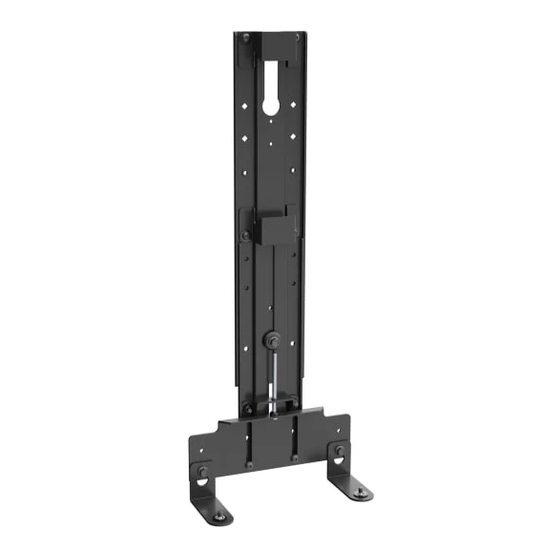
Fusion® Display Mount Accessory For Logitech® Rally Bar/Rally Bar Mini
Above Wall
Below Wall
Spanish Product Description
German Product Description
Portuguese Product Description
Italian Product Description
Dutch Product Description
French Product Description
FCALRB1
Above Cart/Ceiling/
Freestanding
Below Cart/Ceiling/
Freestanding
Advertisement

Related Manuals for LEGRAND CHIEF Fusion FCALRB1


Summary of Contents for LEGRAND CHIEF Fusion FCALRB1
- Page 1 I N S T A L L A T I O N I N S T R U C T I O N S Above Cart/Ceiling/ Freestanding Above Wall Below Wall Below Cart/Ceiling/ Freestanding Fusion® Display Mount Accessory For Logitech® Rally Bar/Rally Bar Mini Spanish Product Description German Product Description Portuguese Product Description...
-
Page 2: Important Safety Instructions
The information contained in this document is subject to change without notice or obligation of any kind. Legrand makes no representation of warranty, expressed or implied, regarding the information contained herein. Legrand assumes no responsibility for accuracy, completeness or sufficiency of the information contained in this document. - Page 3 Installation Instructions FCALRB1 DIMENSIONS 670.6 26.40 578.1 22.76 425.1 16.74 618.6 558.4 21.98 24.35 465.8 18.34 DIMENSIONS: INCHES [MILLIMETERS]...
- Page 4 FCALRB1 Installation Instructions DIMENSIONS (CONTINUED) 414.7 16.33 507.3 19.97 567.7 22.35 455.4 548.2 17.93 21.58 608.4 23.95 DIMENSIONS: INCHES [MILLIMETERS]...
-
Page 5: Tools Required For Installation
Installation Instructions FCALRB1 LEGEND Tighten Fastener Phillips Screwdriver Apretar elemento de fijación Destornillador Phillips Befestigungsteil festziehen Kreuzschlitzschraubendreher Apertar fixador Chave de fendas Phillips Serrare il fissaggio Cacciavite a stella Bevestiging vastdraaien Kruiskopschroevendraaier Serrez les fixations Tournevis à pointe cruciforme Loosen Fastener Open-Ended Wrench Aflojar elemento de fijación Llave de boca... -
Page 6: Assembly And Installation
FCALRB1 Installation Instructions ASSEMBLY AND INSTALLATION Below Installation Pre-Installation NOTE: The Rally Bar may be installed above or below displays between 55" and 84". To install above display, proceed Remove the lower adjustment assembly (H) from the to Above Installation section. upright assembly (A) and set aside. - Page 7 Installation Instructions FCALRB1 Use 1/4-20 x 5/8” hex head flange screw (G) and center Attaching to Cart/Ceiling/Freestanding Mount washer (F) to secure lower adjustment assembly (J) to Slide upright bracket (A) onto front of cart/ceiling/ upright assembly (A). freestanding mount head assembly until edge rail bracket •...
- Page 8 FCALRB1 Installation Instructions Above Installation Use 1/4-20 x 5/8” hex head flange screw (F) and center washer (G) to secure lower adjustment assembly (J) to upright assembly (A). Attaching to Wall Mount • (Maximum macro extension) Slide lower adjustment assembly (J) until top of channel stops against 1/4-20 x 5/8"...
- Page 9 Installation Instructions FCALRB1 Use 1/4-20 x 5/8” hex head flange screw (G) and center Attaching to Cart/Ceiling/Freestanding Mount washer (F) to secure lower adjustment assembly (J) to Slide upright assembly (A) onto front of cart/ceiling/ upright assembly (A). freestanding mount head assembly until center rail bracket •...
- Page 10 FCALRB1 Installation Instructions Use 1/4-20 x 5/8” hex head flange screw (G) and center washer (F) to secure lower adjustment assembly (J) to upright assembly (A). • (Maximum macro extension) Slide lower (K) x 2 adjustment assembly (J) until bottom of channel rests against 1/4-20 x 5/8"...
- Page 11 Installation Instructions FCALRB1 Micro Adjustment Alternative Camera Installation Method NOTE: The interface assemblies (K) can be installed to the IMPORTANT ! : Make sure all macro adjustments have camera prior to being installed to the lower adjustment been made prior to making micro adjustments. Full assembly if desired.
- Page 12 P +31 (0) 495 580 852 F +31 (0) 495 580 845 Asia Pacific A Office No. 918 on 9/F, Shatin Galleria 8800-003387 Rev00 18-24 Shan Mei Street 2023 Legrand Fotan, Shatin, Hong Kong www.legrandav.com P 852 2145 4099 05/2023 F 852 2145 4477...
Need help?
Do you have a question about the CHIEF Fusion FCALRB1 and is the answer not in the manual?
Questions and answers