Table of Contents
Advertisement
Quick Links
Advertisement
Table of Contents

Related Manuals for LEGRAND CHIEF Fusion FCA812


Summary of Contents for LEGRAND CHIEF Fusion FCA812
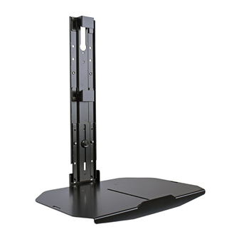
- Page 1 I N S T A L L A T I O N I N S T R U C T I O N S Below Cart/Ceiling Below Wall Fusion™ X-Large Below Component Shelf Spanish Product Description German Product Description Portuguese Product Description Italian Product Description Dutch Product Description French Product Description...
-
Page 2: Installation Instructions
FCA812 Installation Instructions DISCLAIMER WARNING: RISK OF INJURY TO PERSONS! Do not use Milestone AV Technologies and its affiliated corporations and this mounting system to support video equipment such as subsidiaries (collectively “Milestone”), intend to make this televisions or computer monitors. manual accurate and complete. - Page 3 Installation Instructions FCA812 DIMENSIONS FUSION WALL BELOW MOUNT SETUP 18.0-19.7 [455.9-499.1] MIN RANGE 19.7-29.5 [499.1-750.3] INTERMEDIATE RANGE 29.5-30.9 [750.3-784.9] MAX RANGE (*)NOTES: • TYPICAL FUSION INTERFACES ARE 0.5" [12.7] DEEP 18.0 457.2 FUSION CEILING BELOW MOUNT SETUP 17.9-19.6 [454.7-496.6] MIN RANGE 19.6-27.8 [496.6-704.9] INTERMEDIATE...
-
Page 4: Tools Required For Installation
FCA812 Installation Instructions LEGEND Tighten Fastener Phillips Screwdriver Apretar elemento de fijación Destornillador Phillips Befestigungsteil festziehen Kreuzschlitzschraubendreher Apertar fixador Chave de fendas Phillips Serrare il fissaggio Cacciavite a stella Bevestiging vastdraaien Kruiskopschroevendraaier Serrez les fixations Tournevis à pointe cruciforme Loosen Fastener Open-Ended Wrench Aflojar elemento de fijación Llave de boca... -
Page 5: Assembly And Installation
Installation Instructions FCA812 ASSEMBLY AND INSTALLATION Attaching Shelf to Wall Mount NOTE: NOTE: FCA812 shelves may ONLY be installed below If attaching to cart or ceiling mount, proceed to Attach displays. Shelf to Cart/Ceiling Section. Assembling Shelf to Upright Bracket Use two 1/4-20 x 1/4”... - Page 6 FCA812 Installation Instructions NOTE: Refer to Table 1 and dimension drawings on page 3 to determine the extension level based on extension (Below wall - minimum) distance from mount center. Below Wall Mount Table 1: holes to use for intermediate Extension distance from center of mount (in.) configurations 18-19.7...
- Page 7 Installation Instructions FCA812 Slide second shelf bracket (C) underneath head assembly, Slide second shelf bracket (C) underneath head assembly, lining up holes on shelf bracket (C) to holes on main bracket lining up holes on shelf bracket (C) to holes on main bracket (B).
-
Page 8: Height Adjustment
FCA812 Installation Instructions Height Adjustment (Below cart/ceiling Maximum) Loosen hardware used to attach main bracket (B) to upright (rear view) bracket (A). (See Figure 13) Adjust shelf height as desired. (See Figure 13) Tighten hardware used to attached main bracket (B) to upright bracket (A). - Page 9 Installation Instructions FCA812 Installing Components (not included) WARNING: Exceeding the weight capacity can result in serious personal injury or damage to equipment! It is the installer’s responsibility to make sure the combined weight mounted on the FCA812 does not exceed 20 lbs (9.1 kg). WARNING: Components must be secured to FCA812 shelf using either adhesive hook and loop squares (T) or screw...
- Page 10 FCA812 Installation Instructions...
- Page 11 Installation Instructions FCA812...
- Page 12 FCA812 Installation Instructions USA/International A 6436 City West Parkway, Eden Prairie, MN 55344 P 800.582.6480 / 952.225.6000 F 877.894.6918 / 952.894.6918 Europe A Franklinstraat 14, 6003 DK Weert, Netherlands P +31 (0) 495 580 852 F +31 (0) 495 580 845 Chief, a products division of Asia Pacific A Office No.
Need help?
Do you have a question about the CHIEF Fusion FCA812 and is the answer not in the manual?
Questions and answers