Advertisement
I N S T A L L A T I O N I N S T R U C T I O N S
Instrucciones de instalación
Installationsanleitung
Instruções de Instalação
XPA1U/XFA1U Dual Monitor Extension Accessory
Istruzioni di installazione
Installatie-instructies
Instructions d´installation
Spanish Product Description
German Product Description
Portuguese Product Description
Italian Product Description
Dutch Product Description
French Product Description
FCA624
Advertisement
Table of Contents

Related Manuals for LEGRAND CHIEF FCA624


Summary of Contents for LEGRAND CHIEF FCA624
- Page 1 I N S T A L L A T I O N I N S T R U C T I O N S Instrucciones de instalación Istruzioni di installazione Installationsanleitung Installatie-instructies Instruções de Instalação Instructions d´installation XPA1U/XFA1U Dual Monitor Extension Accessory Spanish Product Description German Product Description Portuguese Product Description...
-
Page 2: Important Safety Instructions
The information contained in this document is subject to change without notice or obligation of any kind. Legrand makes no representation of warranty, expressed or implied, 125 lbs (56.7 kg) per display regarding the information contained herein. - Page 3 Installation Instructions FCA624 DIMENSIONS FCA624 SHOW N ON XPA1U FOR REFERENCE. ORDER XPA1U SEPERATELY 8" FILLER PANEL ASSEMBLY SHOW IN LOW POSITION. 8" FILLER ASSEMBLY IS INCLUDED WITH THE FCA624 72.88 1851.1 [100X100] MIN [600X400] MAX 15.75 17.00 400.0 431.8...
- Page 4 FCA624 Installation Instructions LEGEND Tighten Fastener Pencil Mark Apretar elemento de fijación Marcar con lápiz Befestigungsteil festziehen Stiftmarkierung Apertar fixador Marcar com lápis Serrare il fissaggio Segno a matita Bevestiging vastdraaien Potloodmerkteken Serrez les fixations Marquage au crayon Loosen Fastener Drill Hole Aflojar elemento de fijación Perforar...
-
Page 5: Tools Required For Installation
Installation Instructions FCA624 TOOLS REQUIRED FOR INSTALLATION 1/8” (included) 3/16” (included) 1/2” PARTS A (2) [Left upright] B (2) [Right upright] H (2) [Hardware bag B - quantities listed per bag] HD (4) HE (4) HA (4) HB (4) HC (4) C (1) 1/4”... -
Page 6: Assembly And Installation
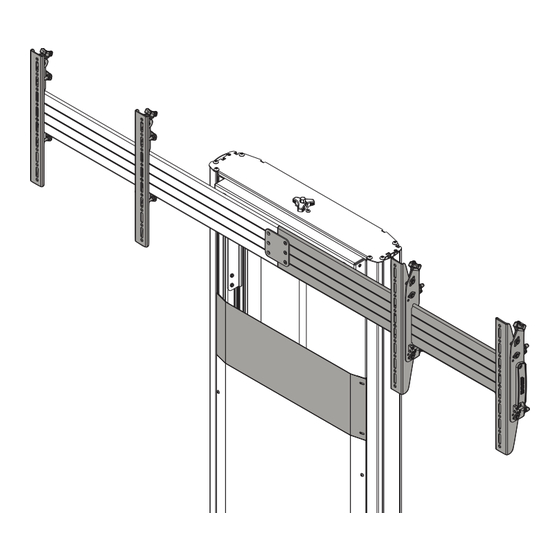
FCA624 Installation Instructions Assembly And Installation Remove four nuts holding interface head assembly to XP1AU/XFA1U column assembly to remove head assembly. (See Figure 3) The FCA624 is specifically designed to convert Chief’s XPA1U carts or XFA1U floor to wall stand mounts into 2x1 monitor mounting systems. - Page 7 Installation Instructions FCA624 (rear view) connecting brackets (G x 3/removed screws x 3) front plate on top removed nuts x 4 back plate tilt plate Figure 5 Slide two of four connecting brackets from XPA1U/XFA1U head assembly into corresponding groove on FCA624 interface.
-
Page 8: Display Installation
FCA624 Installation Instructions Display Installation CAUTION: Place display face down on a soft, non-abrasive surface. Using screws of improper length may damage your display! Proper screws will have adequate thread NOTE: For best access, route display cables through columns engagement without contacting bottom of display mounting prior to display installation. - Page 9 Installation Instructions FCA624 WARNING: Exceeding the weight capacity can result in serious personal injury or damage to equipment! It is the (F) x 2 installer’s responsibility to make sure the combined weight of each display and attached accessories does not exceed 250 lbs (113.4 kg) or 125 lbs (56.7 kg) per display after the FCA624 accessory has been installed to the XPA1U/XFA1U.
-
Page 10: Height Adjustment
FCA624 Installation Instructions Adjustments Height Adjustment Use upper knob on back of interface brackets (A and B) to adjust the height of each display. (See Figure 12) NOTE: Adjust both brackets in order to maintain a level mount. Plumb Adjustment Use middle and lower knobs on back of interface brackets (A and B) to make plumb adjustments to each display. - Page 11 Installation Instructions FCA624...
- Page 12 P +31 (0) 495 580 852 F +31 (0) 495 580 845 Asia Pacific A Office No. 918 on 9/F, Shatin Galleria 8800-002902 Rev01 18-24 Shan Mei Street 2021 Legrand Fotan, Shatin, Hong Kong www.legrandav.com P 852 2145 4099 10/2021 F 852 2145 4477...
Need help?
Do you have a question about the CHIEF FCA624 and is the answer not in the manual?
Questions and answers