Table of Contents
Advertisement
Quick Links
Advertisement
Table of Contents

Related Manuals for Gree GWH09AOCXD-K6DNA1B


Summary of Contents for Gree GWH09AOCXD-K6DNA1B
- Page 1 Change for life Service Manual GREE ELECTRIC APPLIANCES, INC. OF ZHUHAI...
-
Page 2: Table Of Contents
Table of Contents Service Manual Part Ⅰ : Technical Information ........1 1. Summary ................. 1 2. Specifications ............... 2 2.1 Specification Sheet ................... 2 2.2 Capacity Variation Ratio According to Temperature ......6 3. Outline Dimension Diagram ........7 3.1 Indoor Unit .................... - Page 3 Service Manual 8.9 Vacuum Pumping and Leak Detection ..........33 8.10 Check after Installation and Test Operation ........34 9. Maintenance ..............35 9.1 Judgement by Flashing LED of Indoor ..........35 9.2 Malfunction detection process .............. 42 9.3 Controller Assembly and Maintenance Diagram ......... 45 9.4 Troubleshooting for Normal Malfunction ..........
-
Page 4: Part Ⅰ : Technical Information
Outdoor Unit: GWH09AOCXD-K6DNA1B/O GWH12AOCXD-K6DNA1B/O Remote Controller: YAA1FB16(WiFi) I SENSE Model list: Indoor product Outdoor Model Product code Indoor model Outdoor model code product code 1 GWH09AOCXD-K6DNA1B CB538000400 GWH09AOCXD-K6DNA1B/I CB538N00400 GWH09AOCXD-K6DNA1B/O CB538W00400 2 GWH12AOCXD-K6DNA1B CB538000300 GWH12AOCXD-K6DNA1B/I CB538N00300 GWH12AOCXD-K6DNA1B/O CB538W00300 Technical Information... -
Page 5: Specifications
2. Specifications Service Manual 2.1 Specification Sheet Model GWH09AOCXD-K6DNA1B Product Code CB538000400 Rated Voltage 220-240 Power Rated Frequency Supply Phases Power Supply Mode Indoor Cooling Capacity 2700 Heating Capacity 4500 Cooling Power Input Heating Power Input 1070 Cooling Power Current... - Page 6 Service Manual Outdoor Unit Model GWH09AOCXD-K6DNA1B/O Outdoor Unit Product Code CB538W00400 Compressor Manufacturer ZHUHAI LANDA COMPRESSOR CO.,LTD Compressor Model QXF-B103zH170F Compressor Oil RB68GX or equivalent Compressor Type Rotary Compressor LRA. 25.00 Compressor RLA 4.00 Compressor Power Input Compressor Overload Protector...
- Page 7 Service Manual Model GWH12AOCXD-K6DNA1B Product Code CB538000300 Rated Voltage 220-240 Power Rated Frequency Supply Phases Power Supply Mode Indoor Cooling Capacity 3700 Heating Capacity 4800 Cooling Power Input Heating Power Input 1116 Cooling Power Current Heating Power Current Rated Input 2196 Rated Cooling Current Rated Heating Current...
- Page 8 Service Manual Outdoor Unit Model GWH12AOCXD-K6DNA1B/O Outdoor Unit Product Code CB538W00300 Compressor Manufacturer ZHUHAI LANDA COMPRESSOR CO.,LTD Compressor Model QXF-B103zH170F Compressor Oil RB68GX or equivalent Compressor Type Rotary Compressor LRA. 25.00 Compressor RLA 4.00 Compressor Power Input Compressor Overload Protector Throttling Method Electron expansion valve Set Temperature Range...
-
Page 9: Capacity Variation Ratio According To Temperature
Service Manual 2.2 Capacity Variation Ratio According to Temperature Cooling Heating 160% 120% 140% 100% 120% 100% Condition Conditions Indoor:DB27°C WB19°C Indoor:DB20°C Indoor air flow: High Indoor air flow:Super High Pipe length:5m Pipe length:5m Technical Information... -
Page 10: Outline Dimension Diagram
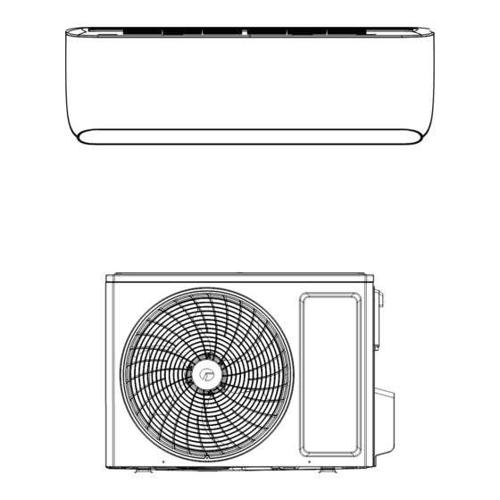
3. Outline Dimension Diagram Service Manual 3.1 Indoor Unit 80.8 124.8 124.8 Unit:mm 3.2 Outdoor Unit Unit:mm Technical Information... -
Page 11: Refrigerant System Diagram
4. Refrigerant System Diagram Service Manual Cooling and heating model Indoor unit Outdoor unit Gas pipe side Valve 4-Way valve Di s charge Heat Suction Accumlator exchanger Compressor (evaporator) Heat exchanger Liquid pipe (condenser) side Valve Strainer Electric Strainer expand valve COOLING HEATING... -
Page 12: Electrical Part
Symbol Color Symbol Name Yellow Brown COMP Compressor Blue Grounding wire YEGN Yellow/Green Black Note: Jumper cap is used to determine fan speed and the swing angle of horizontal lover for this model. ● Indoor Unit GWH09AOCXD-K6DNA1B/I GWH12AOCXD-K6DNA1B/I 600007063838 Technical Information... - Page 13 Service Manual ● Outdoor Unit GWH09AOCXD-K6DNA1B/O GWH12AOCXD-K6DNA1B/O 600007066077 These wiring diagrams are subject to change without notice; please refer to the one supplied with the unit. Technical Information...
-
Page 14: Pcb Printed Diagram
Service Manual 5.2 PCB Printed Diagram Indoor unit mainboard Name Name Interface of grounding wire Left&right swing interface Live wire of outdoor unit Interface of fresh air pipe switch Live wire of indoor unit Interface of fresh air motor Neutral wire of discharge motor Interface of CO module Live wire of discharge motor... - Page 15 Service Manual Outdoor Unit Name Name Grounding wire,Live wire, neutral wire and communication wire integrated Interface of temperature sensor interface Interface of 4-way valve Interface of compressor Interface of outdoor fan Interface of electronic expansion valve Technical Information...
-
Page 16: Function And Control
6. Function and Control Service Manual 6.1 Remote Controller Introduction of YAA1FB16(WiFi) Buttons on remote controller Introduction for buttons on remote controller 1. ON/OFF button 5. LIGHT button ● Press this button to turn on/off the air conditioner. ● Press this button to control the LED status on the displayer, the ●... - Page 17 Service Manual 1. ON/OFF button button, time value will change quickly), the setting range is 0.5~24 hour(s); press this button again to confirm timer, the character of H ● Press this button to turn on/off the air conditioner. and OFF (ON) will not blink any more. ●...
- Page 18 Service Manual perform fast cooling or fast heating. There may be some noise, which is the sound of flowing liquid or thermal expansion or cold shrinkage. The air conditioner may blow cool or warm air, which is a normal phenomenon. During cleaning process, please make sure the room is well ventilated to avoid affecting the comfort.
-
Page 19: Description Of Each Control Operation
Service Manual 6.2 Description of Each Control Operation ● Indoor unit set fan speed. The compressor, outdoor fan, 4-way valve and electric heating tube stop operation. Under this mode, temperature setting range is 16~30 ℃ . 1. This controller design has the following functions: The display displays the set temperature. - Page 20 Service Manual 7. Left&right swing control: 3. Fresh air function (only for the model with fresh air function) Select different left&right swing directions according to the left&right swing remote control status. Left position ① , ① Indoor environment indicator second left position ② , middle position ③ , second right The fresh air model is equipped with the CO sensor to position ④...
- Page 21 Service Manual the lower limit for 10min}, the unit will stop for reaching the When the above conditions are met at the same time, temperature point in cooling, or enter the ultra-low frequency it will enter defrosting for the first time. At this time, the operation mode;...
- Page 22 Service Manual 6. Malfunction of temperature sensor: Name of temperature sensor Malfunction condtions Always detect open circuit or Outdoor ambient temperature short circuit malfunction of the temperature sensor; Short circuit detection: Perform short circuit detection of the temperature sensor at all times (the AD sampling value corresponding to the highest temperature that can be detected by the outdoor suction...
-
Page 23: Part Ⅱ : Installation And Maintenance
7. Notes for Installation and Maintenance Service Manual Safety Precautions: Important! be installed in the circuit. The air switch should be all-pole parting and the contact parting distance should be more than 3mm. Please read the safety precautions carefully before installa- tion and maintenance. - Page 24 Service Manual Safety Precautions for Installing and Relocating the Unit: To ensure safety, please be mindful of the following precautions. WARNINGS 1. When installing or relocating the unit, be sure to keep the If compressor starts running when stop valve is open and refrigerant circuit free from air or substances other than the connection pipe is not yet connected, air will be sucked in and specified refrigerant.
- Page 25 Service Manual Installation notes Safety Precautions for Refrigerant ●To realize the function of the air conditioner unit, a special ●The air conditioner is not allowed to use in a room that refrigerant circulates in the system. The used refrigerant is has running fire (such as fire source,working coal gas ware, the fluoride R32,which is specially cleaned.
- Page 26 Service Manual Welding Make sure that different kinds of refrigerant wont contaminate with each other. ●If you should cut or weld the refrigerant system pipes in the ●The refrigerant tank should be kept upright at the time of process of maintaining, please follow the steps as below: filling refrigerant.
- Page 27 Service Manual Main Tools for Installation and Maintenance Level meter Measuring tape Screw driver Impact drill Drill head Electric drill Electroprobe Universal meter Inner hexagon Electronic Torque wrench Open-end wrench spanner leakage detector Vacuum pump Pressure meter Pipe pliers Pipe pliers Pipe cutter Pipe expander Pipe bender...
-
Page 28: Installation
8. Installation Service Manual 8.1 Installation Dimension Diagram Space to the wall At least 15cm At least 15cm Space to the wall Drainage pipe Installation and Maintenance... - Page 29 Service Manual Installation Procedures Start installation Preparation before installation Read the requirements select installation Prepare tools for electric connection location Select indoor unit Select outdoor unit installation location installation location Install wall-mounting Install the support of outdoor unit (select it according to the actual situation) frame, drill wall holes Connect pipes of indoor Fix outdoor unit...
-
Page 30: Installation Parts-Checking
Service Manual 8.2 Installation Parts-checking unit. 4. Make sure that the installation follows the requirement of Name installation dimension diagram. 5. Select a location which is out of reach for children and far away Indoor unit from animals or plants. If it is unavoidable, please add fence for Outdoor unit safety purpose. -
Page 31: Name Description Of Components In The Accessory Box
Service Manual 8.5 Name Description of Components in the Accessory Box 2. Connect the drain pipe ● Connect the drain pipe in the accessory to the outlet pipe of the indoor unit, and fix it with two rounds of electrical tape. ●... - Page 32 Service Manual user, distinguish the front and back, finally cover the healthy filter cover and panel. 6. Confirm the position of pipe outlet and drill a hole ● Confirm the position of pipe outlet The pipe can be leaded out from the left, right and back side of unit.
-
Page 33: Installation Instructions For Fresh Air Ventilation Device (Exhaust)
Service Manual Note: No ventilation connection wire for the models without air suitable, please drill a hole with the diameter of 63mm according discharge function. to the installation position of indoor unit. Please note that the hole should tilt from inside to outside. Note: Please do not damage the wires embedded in the wall when making holes. - Page 34 Service Manual 2.Connect the joint (exhaust) and fresh air pipe (exhaust) in 3.Choose the installation location in the outdoor side as shown in place. the figure. 3.Thread the connected fresh air pipe (exhaust) through the wall hole, and fix the joint (exhaust) on the wall with three screws (expansion rubber particles are required).
-
Page 35: Installation Of Outdoor Unit
Service Manual 4. Connection of outdoor ventilation cable 2. Install Drain Joint(Only for some models) 1.Unscrew the screws and open the cover of electrical box (see 1. Connect the outdoor drain joint into the hole on the chassis, as figure a); shown in the picture below. -
Page 36: Vacuum Pumping And Leak Detection
Service Manual 4. Tighten the union nut with torque wrench by referring to the sheet below. 5. Connect Outdoor Electric Wire 1. Remove the wire clip; connect the power connection wire (only for cooling and heating unit) to the wiring terminal according to the color;... -
Page 37: Check After Installation And Test Operation
Service Manual 8.10 Check after Installation and Test Operation 1. Check after Installation Check according to the following requirement after finishing installation. Items to be checked Possible malfunction Has the unit been installed The unit may drop, shake or firmly? emit noise. -
Page 38: Maintenance
9. Maintenance Service Manual 9.1 Judgement by Flashing LED of Indoor Display method of indoor unit (Indicator has 3 kinds Display of display status and method they will be displayed of indoor No. Malfunction name A/C status Possible causes circularly every 5s) unit □... - Page 39 Service Manual 1. Indoor or outdoor ambient temperature is too high? Cooling: compressor and 2. Indoor or outdoor fan operates outdoor fan stop, while indoor High temperature □ (3s) abnormally? fan operates protection ☆ (6 times) 3. Filter or condenser is blocked Heating: compressor, outdoor with dirt? fan and indoor fan stop...
- Page 40 Service Manual Defrosting During defrosting, the defrosting Compressor operates, outdoor The complete unit enters defrosting light is displayed fan stops, and indoor fan mode, which belongs to normal (or power operates operation situation. indicator blinks for 10s and is off for 0.5s) 1.
- Page 41 Service Manual 1. Control board and compressor are reliably connected? Is it loose? Connection sequence is correct? 2. Compressor coil resistance is normal? Insulation of compressor coil to copper pipe is good? 3. Outdoor fan is abnormal? Cooling: compressor and Compressor 4.
- Page 42 Service Manual 1. Control board and compressor are reliably connected? Is it loose? Connection sequence is correct? 2. Compressor coil resistance is normal? Insulation of compressor coil to copper pipe is good? 3. Outdoor fan is abnormal? Cooling: compressor and 4.
- Page 43 Service Manual 1. Measure the power supply voltage to see if it is too low or it is Cooling: compressor and dragged down as the power supply outdoor fan stop, while indoor Low voltage □ (3s) capacity is insufficient? fan operates protection ☆...
- Page 44 Service Manual Self-detection flow chart of inverter outdoor unit: Connect the self-detection tooling according to the requirements IDU mainboard is damaged Replace the IDU mainboard Self-detection tooling If the automatically locates the complete unit displays detailed malfunction position E6 malfunction and gives indication Replace the IDU mainboard...
-
Page 45: Malfunction Detection Process
Service Manual 9.2 Malfunction detection process 1. Troubleshooting of pipe temperature sensor malfunction Troubleshooting for temperature sensor malfunction Is the wiring terminal between the temperature sensor and the control board loose or poorly contacted? Insert the temperature sensor tightly Is malfunction eliminated Is there short circuit due to trip-over of the... - Page 46 Service Manual 2. Troubleshooting of PG motor blockage protection H6 Troubleshooting for H6 malfunction Is the feedback terminal of PG motor connected tightly Insert the feedback terminal of PG motor tightly Is malfunction eliminated Is the control terminal of PG motor connected tightly Insert the control terminal of PG motor tightly...
- Page 47 Service Manual 3. Troubleshooting of jumper cap malfunction C5 Troubleshooting for C5 malfunction there jumper cap on the controller Assemble the jumper cap with the same model Is malfunction eliminated Is the jumper cap inserted correctly and tightly Insert the jumper cap tightly Is malfunction eliminated...
-
Page 48: Controller Assembly And Maintenance Diagram
Service Manual 9.3 Controller Assembly and Maintenance Diagram 1. (The following is the disassembly process, and the installation should be carried out from back to front) After removing the electric box assy, open clasp 1 and 2 or clasp 3 and 4 simultaneously to remove the case cover! Clasp3 Clasp1 Clasp2... - Page 49 Service Manual Detection method: Use multimeter diode for detection; Procedures: a. Put the black probe of multimeter on “+” side of rectifier bridge, that is position 1 on the following figure. The red probe contacts position 2 and 3 of the rectifier bridge respectively, that is the AC input side marked with “~”. Read the display value of the multimeter respectively.
-
Page 50: Troubleshooting For Normal Malfunction
Service Manual 9.4 Troubleshooting for Normal Malfunction 1. Air Conditioner can't be Started Up Possible Causes Discriminating Method (Air conditioner Status) Troubleshooting Confirm whether it's due to power failure. If yes, No power supply, or poor connection After energization, operation indicator isnt bright wait for power recovery. - Page 51 Service Manual 4. ODU Fan Motor can't Operate Possible causes Discriminating method (air conditioner status) Troubleshooting Connect wires according to wiring diagram to Wrong wire connection, or poor Check the wiring status according to circuit diagram make sure all wiring terminals are connected connection firmly Measure the capacity of fan capacitor with an...
-
Page 52: Exploded View And Parts List
10. Exploded View and Parts List Service Manual 10.1 Indoor Unit The component picture is only for reference; please refer to the actual product. Installation and Maintenance... - Page 53 Service Manual Description Description Wall Mounting Frame Sub-assy Air Deflector Sub-assy Evaporator Assy Front Panel Assy Evaporator Support Crank Drainage Hose Stepping Motor Cross Flow Fan Stepping Motor O-Gasket sub-assy of Bearing Right Side Plate Assy Filter Sub-Assy Air Louver 2 Electric Heater Stepping Motor Rear Case assy...
-
Page 54: Outdoor Unit
Service Manual 10.2 Outdoor Unit The component picture is only for reference; please refer to the actual product. Installation and Maintenance... - Page 55 Service Manual Description Description Top Cover Assy Grill Chassis Sub-assy Condenser Assy Front Panel Assy 4-Way Valve Front Grill Sensor Insert Axial Flow Fan 4-Way Valve Assy Brushless DC Motor Electric Expansion Valve Fitting Motor Support Electric Expansion Valve Sub-Assy Left Side Plate Wire Clamp Clapboard...
-
Page 56: Fresh Air Ventilation Device (Exhaust)
Service Manual 10.3 Fresh Air Ventilation Device (Exhaust) Description Ventilation Box Cover Transformer Brushless DC Ventilation Fan Electric Box Cover Rubber Band Motor Plate Electric Expansion Valve Sub-Assy Some models may not contain some parts, please refer to the actual product. Installation and Maintenance... -
Page 57: Removal Procedure
11. Removal Procedure Service Manual 11.1 Removal Procedure of Indoor Unit Caution: discharge the refrigerant completely before removal. Step Procedure 1. Complete unit 2. Remove air deflector a. Rotate the big and small air deflectors to the position as shown in the figure. b. - Page 58 Service Manual Step Procedure 3. Remove panel assy Screw of Panel display Display a. Open the panel; b. Remove the screw of the display; c. Remove the panel assy. 4. Remove electric box cover, display, upper cover, and front grill sub-assy Front grill Display Electric...
- Page 59 Service Manual Step Procedure 6. Remove front case assy Front case Clasp of front case a. Disconnect the wiring terminal of up&down swing motor; b. Remove the 6 fastening screws as shown in the figure; c. Break off the 4 clasps of front case as shown in the figure;...
- Page 60 Service Manual Step Procedure 9. Remove electric box assy Screws of grounding wire Fastening screw of electric box Fastening screw a. Remove the fastening screw of wire clamp; b. Remove the 2 screws of grounding wire; c. Remove the fastening screw of electric box; d.
- Page 61 Service Manual Step Procedure 12. Remove evaporator assy Fastening screw of Evaporator evaporator support assy a. Using the screwdriver to remove the 2 fastening screws. b. Break off the connecting pipe on the evaporator assy. c. Remove the evaporator assy to separate the evaporator assy from the rear case.
-
Page 62: Removal Procedure Of Outdoor Unit
Service Manual 11.2 Removal Procedure of Outdoor Unit Warning: Be sure to wait for a minimum of 20 minutes after turning off all power supplies and discharge the refrigerant completely before removal. Step Procedure 1. Before disassembly 2. Remove big handle and valve cover big handle Remove the screws fixing big handle, valve cover and then remove them. - Page 63 Service Manual Step Procedure 4. Remove front panel assy Remove connection screws connecting the front panel assy with the chassis and the motor support, and then remove the front panel assy. Front Panel Assy 5. Remove right side plate assy Rescrew the ground screws, remove the ground wires, loosen the screws fixing terminal board, remove the terminal board, rescrew the screws fixing the right...
- Page 64 Service Manual Step Procedure 7. Remove electric box assy Remove the terminals, lift up and rotate the electrical box assy to the right so that the snaps on the clapboard are removed and the electrical box assy are removed. 8. Remove motor 8.
- Page 65 Service Manual Step Procedure 10. Remove valve suppprt Remove the valve support bolck, remove the screws fixing the gas valve and the liquid valve, Remove the screws fixing valve support, then remove the valve support. valve supprt 11.Remove gas valve and liquid valve Unsolder the welding joint connecting the gas valve and the liquid valve, remove them.
- Page 66 Service Manual Step Procedure 13. Remove electronic expansion valve electric expand Remove the terminals of the electric expand valve valve fitting fitting and rotate to remove the electric expand valve electric expansion fitting. valve sub-Assy Unsolder the welding joint connecting the electronic expansion Valve and then remove the electronic expansion valve.
-
Page 67: Appendix
Appendix: Service Manual Appendix 1: Reference Sheet of Celsius and Fahrenheit Conversion formula for Fahrenheit degree and Celsius degree: Tf=Tcx1.8+32 Set temperature Fahrenheit display Fahrenheit Celsius Fahrenheit display Fahrenheit Celsius Fahrenheit display Fahrenheit Celsius temperature(℉) temperature(℉) temperature(℉) (℉) (℃) (℉) (℃)... -
Page 68: Appendix 3: Pipe Expanding Method
Service Manual Appendix 3: Pipe Expanding Method Pipe Note: Improper pipe expanding is the main cause of refrigerant leakage.Please expand Pipe cutter the pipe according to the following steps: A:Cut the pip Leaning Uneven Burr ● Confirm the pipe length according to the distance of indoor unit and outdoor unit. ●... -
Page 69: Appendix 4: List Of Resistance For Temperature Sensor
Service Manual Appendix 4: List of Resistance for Temperature Sensor Resistance Table of Ambient Temperature Sensor for Indoor and Outdoor Units (15K) Temp( Resistance(kΩ) Temp( Resistance(kΩ) Temp( Resistance(kΩ) Temp( Resistance(kΩ) 138.10 49.02 18.75 7.97 128.60 44.31 17.14 7.35 115.00 40.09 15.68 6.79 102.90... - Page 70 JF00304861 GREE ELECTRIC APPLIANCES, INC. OF ZHUHAI Add: West Jinji Rd, Qianshan, Zhuhai,Guangdong, China, 519070 Tel: (+86-756) 8522219 Fax: (+86-756) 8669426 E-mail: global@cn.gree.com www.gree.com For product improvement, specifications and appearance in this manual are subject to change without prior notice.
Need help?
Do you have a question about the GWH09AOCXD-K6DNA1B and is the answer not in the manual?
Questions and answers