Sign In
Upload
Download
Table of Contents
Contents
Add to my manuals
Delete from my manuals
Share
URL of this page:
HTML Link:
Bookmark this page
Add
Manual will be automatically added to "My Manuals"
Print this page
×
Bookmark added
×
Added to my manuals
Manuals
Brands
Gree Manuals
Air Conditioner
4LIV09
Service manual
Gree 4LIV09 Service Manual
Hide thumbs
1
Table Of Contents
2
3
4
5
6
7
8
9
10
11
12
13
14
15
16
17
18
19
20
21
22
23
24
25
26
27
28
29
30
31
32
33
34
35
36
37
38
39
40
41
42
43
44
45
46
47
48
49
50
51
52
53
54
55
56
57
58
59
60
61
62
63
64
65
66
67
68
69
70
71
72
73
74
75
76
77
78
79
80
81
82
83
84
85
86
87
88
89
90
91
92
93
94
95
96
97
98
99
100
101
102
103
104
105
106
107
108
109
110
111
112
113
114
115
116
117
118
119
page
of
119
Go
/
119
Contents
Table of Contents
Troubleshooting
Bookmarks
Table of Contents
Table of Contents
Part I : Technical Information
Summary
Specifications
Specification Sheet
Capacity Variation Ratio According to Temperature
Cooling and Heating Data Sheet in Rated Frequency
Outline Dimension Diagram
Indoor Unit
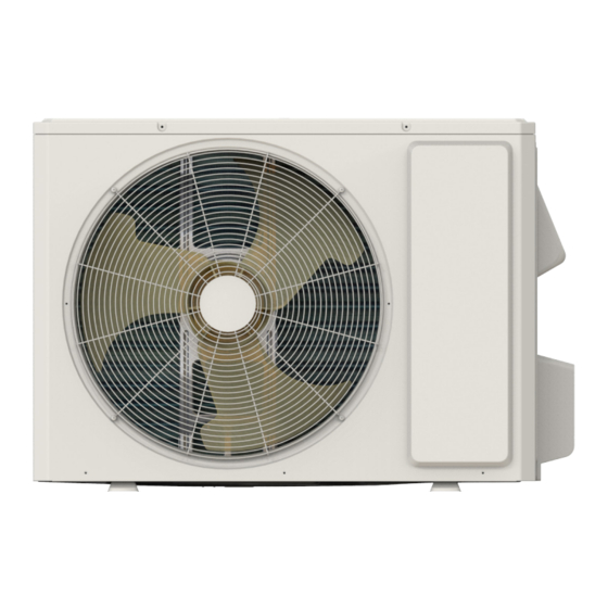
Outdoor Unit
Refrigerant System Diagram
Electrical Part
Wiring Diagram
PCB Printed Diagram
Function and Control
Remote Controller Introduction
GREE+ App Operation Manual
Ewpe Smart App Operation Manual
Brief Description of Modes and Functions
Part II : Installation and Maintenance
Notes for Installation and Maintenance
Installation
Installation Dimension Diagram
Installation Parts-Checking
Selection of Installation Location
Electric Connection Requirement
Installation of Indoor Unit
Installation of Outdoor Unit
Vacuum Pumping and Leak Detection
Check after Installation and Test Operation
Maintenance
Error Code List
Procedure of Troubleshooting
Troubleshooting for Normal Malfunction
Exploded View and Parts List
Indoor Unit
Outdoor Unit
Removal Procedure
Removal Procedure of Indoor Unit
Removal Procedure of Outdoor Unit
Appendix
Appendix 1: Reference Sheet of Celsius and Fahrenheit
Appendix 2: Configuration of Connection Pipe
Appendix 3: Pipe Expanding Method
Appendix 4: List of Resistance for Temperature Sensor
Advertisement
Quick Links
1
Specifications
2
Specification Sheet
3
Indoor Unit
4
Wiring Diagram
5
Remote Controller Introduction
Download this manual
Change for life
Service Manual
4LIV09 - 24 Models
GREE ELECTRIC APPLIANCES, INC. OF ZHUHAI
Table of
Contents
Previous
Page
Next
Page
1
2
3
4
5
Advertisement
Table of Contents
Troubleshooting
Procedure of Troubleshooting
67
Troubleshooting for Normal Malfunction
84
Need help?
Do you have a question about the 4LIV09 and is the answer not in the manual?
Ask a question
Questions and answers
Related Manuals for Gree 4LIV09
Air Conditioner Gree A1 Service Manual
(201 pages)
Heat Pump Gree Dettson LOMO 19 Installation Manual
Single zone ductless heat pump (118 pages)
Air Conditioner Gree A1 Panel Service Manual
(75 pages)
Air Conditioner Gree A1 Service Manual
(33 pages)
Heat Pump Gree Vita GWC09ATCXB-D3DNA3A/I Operation Manual
Cooling only system, heat pump system 115v/230v, freematch indoor units (24 pages)
Heat Pump Gree Livo 4LIV09HP115V1AH Owner's Manual
(22 pages)
Air Conditioner Gree GWH09ACC-K6DNA1F/I Service Manual
(125 pages)
Air Conditioner Gree 4LIV12HP230V1 Service Manual
(119 pages)
Air Conditioner Gree 4LIV30HP230V1A Service Manual
(93 pages)
Air Conditioner Gree 4LIV36HP230V1A Service Manual
(93 pages)
Air Conditioner Gree GWHD 36 NK6RO Service Manual
(66 pages)
Air Conditioner Gree KF-20GW/A20 Service Manual
Gree split type room air conditioners (131 pages)
Air Conditioner Gree VIR09HP115V1A Installation Manual
Gree vir09hp115v1a; vir12hp115v1a; vir09hp230v1a; vir12hp230v1a; vir18hp230v1a; vir24hp230v1a; vir30hp230v1a; vir36hp230v1a air conditioners (31 pages)
Air Conditioner GREE GWH09MB-K3DNA2H/I(DRED) Owner's Manual
Gree gwh09mb-k3dna2h/i(dred); gwh09mb-k3dna4h/i(dred); gwh09mb-k3dna5i/i(dred); gwh12mb-k3dna4h/i(dred); gwh12mb-k3dna5i/i(dred); gwh18mc-k3dna2h/i(dred); gwh18mc-k3dna4h/i(dred); gwh24md-k3dna2h/i(dred); gwh24me-k3dna4a/i(dred); gwh24md-k3dna4h/i(dred); (35 pages)
Air Conditioner Gree Split Air Conditioner Owner's Manual
(28 pages)
Air Conditioner Gree ForestAir 13-04588 Owner's Manual
Window air conditioner (16 pages)
This manual is also suitable for:
Gwc09atcxb-d3dna1a
Gwc09at
Cxb-d3dna3a
Cxb-d3dna4a
Gwh09atcxb-d3dna1a
Gwh09at
...
Show all
Cxb-d3dna2a
Cxb-a3dna1a
Cxb-a3dna3a
Cxb-a3dna4a
Gwc12at
Cxb-d3dna1c
Cxb-d3dna3c
Gwc
12at
Cxb-d3dna4c
Gwh12at
Gwh
Cxb-d3dna2c
12atcxb-a3dna1c
Cxb-a3dna3c
Cxb-a3dna4c
18atdxd-d3dna1a
Gwc18atdxd-d3dna3a
Gwc18atdxd-d3dna4a
18atdxd-d3dna4a
18atdxd-d3dna3a
18atdxd-d3dna2a
Gwc24atexf-d3dna1e
Gwc24atexf-d3dna3e
Gwc24atexf-d3dna4e
Gwh24atexf-d3dna1e
Gwh24atexf-d3dna3e
Gwh24atexf-d3dna4e
Gwc09atcxb-d3dna1a/i
Cxb-d3dna3a/i
Cxb-d3dna4a/i
4liv09hp230v1ah
Cxb-d3dna2a/i
Gwc09atcxb-a3dna1a/i
4liv09hp115v1ah
Cxb-a3dn
A3a/i
A4a/i
Cxb-d3dn
A1
C/i
12atcxb-d3dn
A3c/i
A4c/i
4liv12hp230v1
Ah
Cxb-d3dna4c/i
Cxb-d3dna3c/i
Cxb-d3dna2c/i
4liv12hp115v1ah
Cxb-a3dna3c/i
Cxb-a3dna4c/i
Cxb-a3dna1
18atdxd-d3dna1
A/i
Gwc18atdxd-d3dna3a/i
Gwc18atdxd-d3dna4a/i
4liv18hp230v1ah
18atdxd-d3dna4a/i
18atdxd-d3dna3a/i
18atdxd-d3dna2a/i
Gwc24atexf-d3dna1
E/i
Gwc24atexf-d3dna3e/i
Gwc24atexf-d3dna4e/i
4liv24hp230v1ah
Gwh24atexf-d3dna3e/i
Gwh24atexf-d3dna4e/i
Cb574001000
Cb590000700
Cb595001000
Cb574000900
Cb595000100
Cb590000500
Cb585000600
Cb574001700
Cb574001600
Cb590000300
Cb595000400
Cb574001300
Cb590000800
Cb595001300
Cb574001500
Cb595000200
Cb590000600
Cb585000900
Cb574001400
Cb590000400
Cb595000300
Cb574001200
Cb574003300
Cb590000900
Cb595001100
Cb574003200
Cb595000600
Cb590000100
Cb585000700
Cb574002400
Cb590001000
Cb595001200
Cb574002500
Cb590000200
Cb595000500
Cb574n01000
Cb590n00700
Cb595n01000
Cb574n00900
Cb595n00100
Cb590n00500
Cb585n00600
Cb574n01700
Cb574n01600
Cb590n00300
Cb595n00400
Cb574n01300
Cb590n00800
Cb595n01300
Cb574n01500
Cb595n00200
Cb590
N00600
Cb585n00900
Cb574n01400
Cb590n00400
Cb595n00300
Cb574n01200
Cb574n03300
Cb590n00900
Cb595n01100
Cb574n03200
Cb595n00600
Cb590n00100
Cb585n00700
Cb574n02400
Cb590n01000
Cb595n01200
Cb574n02500
Cb590n00200
Cb595n00500
4liv09 series
4liv09hp230v1ao
4liv09hp115v1a
4liv18hp230v1a
4liv12hp115v1ao
4liv12hp115v1a
4liv09hp115v1ao
4liv12hp230v1ao
4liv18hp230v1ao
4liv24hp230v1a
4liv24hp230v1ao
Cb574w00900
Cb574w01600
Cb574w01500
Cb444w15900
Cb574w01400
Cb574w03200
Table of Contents
Print
Rename the bookmark
Delete bookmark?
Delete from my manuals?
Login
Sign In
OR
Sign in with Facebook
Sign in with Google
Upload manual
Upload from disk
Upload from URL


Need help?
Do you have a question about the 4LIV09 and is the answer not in the manual?
Questions and answers