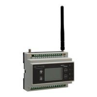
Banner DXM100-S1 Wireless Modbus Slave Manuals
Manuals and User Guides for Banner DXM100-S1 Wireless Modbus Slave. We have 3 Banner DXM100-S1 Wireless Modbus Slave manuals available for free PDF download: Instruction Manual
Banner DXM100-S1 Instruction Manual (119 pages)
Wireless Controller
Brand: Banner
|
Category: Controller
|
Size: 6 MB
Table of Contents
Advertisement
Banner DXM100-S1 Instruction Manual (53 pages)
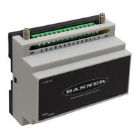
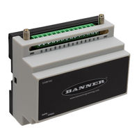
Wireless Modbus Slave
Brand: Banner
|
Category: Controller
|
Size: 1 MB
Table of Contents
Banner DXM100-S1 Instruction Manual (45 pages)
Wireless Modbus Slave
Brand: Banner
|
Category: Controller
|
Size: 1 MB
Table of Contents
Advertisement