
Related Manuals for Banner DXM100-Bx


Summary of Contents for Banner DXM100-Bx
- Page 1 DXM100-Bx Wireless Controller Instruction Manual Instruction Manual Original Instructions 190037 Rev. C 21 October 2016 © Banner Engineering Corp. All rights reserved 190037...
-
Page 2: Table Of Contents
5.1.1 DIP Switches for the I/O Board ..................19 5.1.2 I/O Board Jumpers ......................20 5.2 Applying Power to the DXM100-Bx Wireless Controller ..............20 5.2.1 Using Courtesy Power or Switch Power ................20 5.2.2 Associating a Switched Power Output to an Input .............. - Page 3 DXM100-Bx Wireless Controller Instruction Manual 6.2.4 Supplying Power from a Solar Panel ................. 40 6.3 Working with Solar Power ......................41 6.3.1 Setting the DXM Controller for Solar Power ..............41 6.3.2 Solar Components ......................41 6.3.3 Recommended Solar Configurations ................42 6.3.4 Monitoring Solar Operation...
- Page 4 DXM100-Bx Wireless Controller Instruction Manual 10.3.1 Basic Approach to Configuration ..................73 10.3.2 Troubleshooting a Configuration ..................73 10.3.3 Saving and Loading Configuration Files ................73 10.3.4 Uploading or Downloading Configuration Files ..............73 ™ 10.4 Setting Up EtherNet/IP ......................74 10.4.1 Configuring the Host PLC .....................
-
Page 5: Dxm Overview
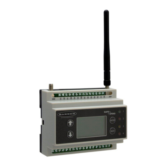
DXM100-Bx Wireless Controller Instruction Manual 1 DXM Overview 1.1 DXM100-Bx System Overview Banner's DXM Logic Controller integrates Banner's wireless radio, cellular connectivity, and local I/O to provide a platform for the Industrial Internet of Things (IIoT). Logic Controller User Interface... -
Page 6: Dxm Automation Protocols
Controller is the Modbus Master when operating the Modbus master RTU port. The DXM Controller uses the master Modbus RTU bus to communicate with locally connected Modbus devices or uses the Banner wireless radio to communicate with remote Modbus devices. The other Modbus RTU port is used by a host system to access the DXM Controller as a slave device. -
Page 7: Dxm Configuration Tool Overview
DXM100-Bx Wireless Controller Instruction Manual DXM Processor ISM Radio (Modbus ID 1) Local Registers (Modbus ID 199) Gateway / MultiHop Local Registers Integer I/O Base (Modbus ID 200) Local Registers Float I/O Base Local Registers Non-Volatile Display (Modbus ID 201) -
Page 8: Dxm Controller
DXM100 I/O Board The DXM100-Bx Wireless Controller I/O base board provides connections for all inputs, outputs and power. The base board also contains a 12 V solar controller that accepts connections to a solar panel and SLA battery. The battery connection can also be used with line power to provide a battery backup in case of line power outages. -
Page 9: Ism Radio Board
DXM100-Bx Wireless Controller Instruction Manual 3 ISM Radio Board 3.1 ISM Radio Board (Modbus Slave ID 1) For the DXM100-S1R2x models, the ISM radio board installed in the I/O board is a MultiHop radio (DX80DR*M-HE5). Plug the ISM radio into the I/O base board with the U.FL antenna connector closest to the SMA connectors. -
Page 10: Dip Switch Settings For The Gateway Pex Board Modules
DXM100-Bx Wireless Controller Instruction Manual D1 Switches D2 Switches Device Settings Application mode: Modbus OFF* Application mode: Transparent MultiHop radio setting: Repeater OFF* OFF* MultiHop radio setting: Master MultiHop radio setting: Slave MultiHop radio setting: Reserved * Default configuration Application Mode The MultiHop radio operates in either Modbus mode or transparent mode. -
Page 11: Binding And Conducting A Site Survey With The Ism Radio
DXM100-Bx Wireless Controller Instruction Manual 3.2 Binding and Conducting a Site Survey with the ISM Radio The DXM Controller can have an internal MultiHop master radio or DX80 Gateway radio (star architecture) installed. Before the ISM radio can communicate with DX80 Nodes, the DXM Controller must be bound to the other radios in the wireless network. -
Page 12: Alternative Modbus Register Organization
DXM100-Bx Wireless Controller Instruction Manual I/O Point Gateway Node 1 Node 2 Node 3 Node 4 Node 5 Node 6 Node 7 Example: DX80 Performance Gateway Modbus Register Table Access all wireless network registers by reading Modbus slave ID 1. - Page 13 DXM100-Bx Wireless Controller Instruction Manual Refer to your device's datasheet for a list of the active inputs and outputs. Not all inputs or outputs listed in this table may be active for your system. Discrete Bit-Packed Registers Discrete bit-packed registers include the discrete status registers, discrete inputs, and discrete outputs.
-
Page 14: Modbus Registers For The Multihop 1 Watt Radio Board
DXM100-Bx Wireless Controller Instruction Manual Output registers from all devices use Modbus registers 6691 through 6753 to organize the least significant bit into a sequential array of registers. Output 8 (I/O point 16) cannot be written using the discrete format. -
Page 15: Processor Board
DXM100-Bx Wireless Controller Instruction Manual 4 Processor Board 4.1 SAM4 Processor Board A - Cellular radio connection B - Force cloud push/Clear password C - Boot load jumpers D - DIP switches LED 1 E - Micro SD card LED 2... -
Page 16: Button Operation
IP addresses, DHCP, etc. The LCD menu allows the user to change the IP Address. 4.3 USB The USB port is used with the DXM Configuration Tool to program the DXM100-Bx Wireless Controller. The USB port is also used as the console output for the processor and ScriptBasic. -
Page 17: Local Registers 851-900 (Data Flash, Non-Volatile, 32-Bit, Unsigned)
DXM100-Bx Wireless Controller Instruction Manual External Modbus device registers can be read into the local registers or written from the local registers. The DXM Controller, as a Modbus master device or a Modbus slave device, exchanges data using the local registers. -
Page 18: Reset Codes
DXM100-Bx Wireless Controller Instruction Manual Registers Definition 10102 Number of read map timeouts 10103 Number of read map errors 10104 Read map success streak 10105 Number of write map successes Write Map statistics 10106 Number of write map timeouts 10107... -
Page 19: O Base Board For The Dxm100-B1 Models
5.1.1 DIP Switches for the I/O Board The DXM100-Bx Wireless Controller I/O board DIP switches are set from the factory to Modbus Slave ID 200. For more information, refer to Setting the Modbus Slave ID on the I/O Base Board. -
Page 20: I/O Board Jumpers
Modbus register 4028 on the I/O board (SID 200) to 3. 5.2 Applying Power to the DXM100-Bx Wireless Controller Apply power to the DXM100-Bx Wireless Controller using either 12 to 30 V dc or a 12 V dc solar panel and 12 V sealed lead acid battery operating together. -
Page 21: Associating A Switched Power Output To An Input
DXM100-Bx Wireless Controller Instruction Manual Switch Power Enable Register Voltage Register Default Output Register Output Register 2 (pin 21) 3622 2251 3621 Write a 0 to turn OFF Write a 0 to select 5 V (default) Write a 1 to turn ON (default) - Page 22 DXM100-Bx Wireless Controller Instruction Manual Voltage For the B1 and S1 models, set the Modbus register value to 0 for a switched power supply at 5 volts. Se the Modbus register value to 1 for a switched power supply at 16 volts.
-
Page 23: Connecting A Battery To The Dxm Controller
5.2.4 Supplying Power from a Solar Panel To power the DXM100-Bx Wireless Controller from a 12 V dc solar panel, connect the solar panel to power pins 2(+) and 3(-). Connect a 12 V dc sealed lead acid (SLA) rechargeable battery to pins 4(+) and 5(-). -
Page 24: Working With Solar Power
DXM100-Bx Wireless Controller Instruction Manual Modbus Slave ID Modbus Register Description 200 * 6071 Battery backup charging algorithm. 0 = Battery is recharged from a solar panel 1 = Battery is recharged from 12 to 30 V dc (default) The following power operating characteristics are stored in Modbus registers. -
Page 25: Solar Components
Solar Panel Banner solar panels come in two common sizes for the DXM Controller: 5 Watt and 20 Watt. Both panels are designed to work with the DXM Controller but provide different charging characteristics. Use the 5 watt panel for light duty operation and use the 20 watt panel when you require greater charging capabilities. -
Page 26: Recommended Solar Configurations
DXM100-Bx Wireless Controller Instruction Manual To capture the maximum amount of solar radiation throughout the year, mount a fixed solar panel to optimize the sun's energy throughout the year. For the northern hemisphere, face the panel true south. For the southern hemisphere, face the panel true north. -
Page 27: Connecting The Communication Pins
CANH + 5.4.1 Modbus RTU Master/Modbus RTU Slave The DXM100-Bx Wireless Controller can be a Modbus RTU master device to other slave devices and can be a Modbus slave device to another Modbus RTU master. The DXM100-Bx Wireless Controller uses the primary RS-485 port as a Modbus RTU master to control external slave devices. -
Page 28: Modbus Slave Port Id
DXM100-Bx Wireless Controller Instruction Manual • Maximum Polling Rate sets the minimum wait time from the end of a Modbus transaction to the beginning of the next Modbus transaction. The Modbus Slave port settings include: • Baud rate and parity (also set on this screen) •... -
Page 29: Universal Inputs
Refer to the Modbus Registers section for more descriptions of each Modbus register on the DXM100-Bx Wireless Controller. 5.6.1 Universal Inputs The universal inputs on the DXM100-Bx Wireless Controller can be programmed to accept several different types of inputs: • Discrete NPN/PNP •... -
Page 30: Nmos Outputs
DXM100-Bx Wireless Controller Instruction Manual Example: Configure Input 1 as a Synchronous Counter 1. Connect the DXM Controller to the PC. 2. Launch the DXM Configuration Tool software. 3. Connect to the DXM Controller by selecting the Device > Connection Settings menu option. You may connect using either USB or Ethernet. -
Page 31: Modbus I/O Registers For The Dxm100-B1 I/O Base Board
DXM100-Bx Wireless Controller Instruction Manual 6. Set the Output Type Select Modbus register (on the I/O board, Slave ID 200) to a value of 2 (default) to select 0 to 20 mA or a value of 3 to select 0 to 10 V. For analog output 1 write to Modbus register 4008, for analog output 2 write to Modbus register 4028 (see the table for the values). - Page 32 DXM100-Bx Wireless Controller Instruction Manual Base Board Input Connection Modbus Register Range Description 0–65535 Universal input 1 0–65535 Universal input 2 0–65535 Universal input 3 0–65535 Universal input 4 Universal Input Register Ranges Register Types Unit Minimum Value Maximum Value...
- Page 33 DXM100-Bx Wireless Controller Instruction Manual Enable Full Scale Set to 1 to enable a linear range from 0 to 65535 for specified input range. For a 4 to 20 mA input, a value of 0 represents 4 mA and 65535 represents 20 mA. Set this parameter to 0 to store input readings in unit-specific data.
-
Page 34: Restoring Factory Default Settings
Only DXM100-S1 and -S1R2 Slave models require that the Modbus Slave ID to be adjusted on the I/O base board. The DXM100-Bx Wireless Controller models use DIP switches J and K to set the Modbus Slave ID. This device can use a Modbus register 6804 in the I/O board to access the full range of Modbus Slave IDs. - Page 35 6804 to set the Modbus Slave ID to any valid Modbus Slave ID (1 through 245). • For the DXM100-Bx Wireless Controller model, all switches on DIP switch K should be in the OFF position to use the Modbus register slave ID.
-
Page 36: O Base Board For The Dxm100-B2 Models
6.1.1 DIP Switches for the I/O Board The DXM100-Bx Wireless Controller I/O board DIP switches are set from the factory to Modbus Slave ID 200. For more information, refer to Setting the Modbus Slave ID on the I/O Base Board. -
Page 37: Applying Power To The Dxm100-Bx Wireless Controller
DXM100-Bx Wireless Controller Instruction Manual 6.2 Applying Power to the DXM100-Bx Wireless Controller Apply power to the DXM100-Bx Wireless Controller using either 12 to 30 V dc or a 12 V dc solar panel and 12 V sealed lead acid battery operating together. -
Page 38: Associating A Switched Power Output To An Input
DXM100-Bx Wireless Controller Instruction Manual Modbus Output Register Turn on or turn off the voltage output. If both outputs 505 and 506 are turned on at the same time but are set to different voltages, the output voltage is 5 V for DXM100-B1 models and set to the lower voltage setting for DXM100-B2 models. - Page 39 DXM100-Bx Wireless Controller Instruction Manual Input Parameter Universal Input Configuration Parameter Modbus Registers Universal Input 1 Universal Input 2 Universal Input 3 Universal Input 4 Switched Power Warmup 1005 1055 1105 1155 Switched Power Voltage 1006 1056 1106 1156 Extended Input Read...
-
Page 40: Connecting A Battery To The Dxm Controller
6.2.4 Supplying Power from a Solar Panel To power the DXM100-Bx Wireless Controller from a 12 V dc solar panel, connect the solar panel to power pins 2(+) and 3(-). Connect a 12 V dc sealed lead acid (SLA) rechargeable battery to pins 4(+) and 5(-). -
Page 41: Working With Solar Power
DXM100-Bx Wireless Controller Instruction Manual Modbus Slave ID Modbus Register Description 6082 Battery charging current (mA) 6083 Incoming supply voltage (mV) (solar or power supply) 6084 On-board thermistor temperature (⁰C) * The Slave ID for the base board is set at the factory. This may be changed using the base board DIP switch settings. -
Page 42: Recommended Solar Configurations
Solar Panel Banner solar panels come in two common sizes for the DXM Controller: 5 Watt and 20 Watt. Both panels are designed to work with the DXM Controller but provide different charging characteristics. Use the 5 watt panel for light duty operation and use the 20 watt panel when you require greater charging capabilities. -
Page 43: Monitoring Solar Operation
RS-485. The primary RS-485 bus is a common bus shared with the ISM radio board (Modbus Slave ID 1) or optional cellular board. The DXM100-Bx Wireless Controller is defined as the Modbus Master on this bus. Other internal Modbus slaves include the local processor registers (Modbus Slave ID 199), the base I/O controller (Modbus Slave ID 200), and the display board (Modbus Slave ID 201). -
Page 44: Modbus Rtu Master/Modbus Rtu Slave
CANH + 6.4.1 Modbus RTU Master/Modbus RTU Slave The DXM100-Bx Wireless Controller can be a Modbus RTU master device to other slave devices and can be a Modbus slave device to another Modbus RTU master. The DXM100-Bx Wireless Controller uses the primary RS-485 port as a Modbus RTU master to control external slave devices. -
Page 45: Modbus Slave Port Id
I/O board and the processor board are fixed. External Modbus communication runs at a maximum rate of 50 ms per transaction. The parameter settings for the external RS-485 buses are controlled by the DXM Configuration Tool. Refer to the Modbus Registers section for more descriptions of each Modbus register on the DXM100-Bx Wireless Controller. -
Page 46: Universal Inputs
DXM100-Bx Wireless Controller Instruction Manual 6.6.1 Universal Inputs The universal inputs on the DXM100-Bx Wireless Controller can be programmed to accept several different types of inputs: • Discrete NPN/PNP • 0 to 20 mA analog • 0 to 10 V analog •... -
Page 47: Nmos Outputs
DXM100-Bx Wireless Controller Instruction Manual 4. Select a COMM port from the drop-down list and click Connect. 5. Click on the Register View tab on the left part of the page. 6. Change the Source Register selection to I/O Board Registers. -
Page 48: Dc Latching Outputs
DXM100-Bx Wireless Controller Instruction Manual Parameter Registers for Analog Outputs (4xxxx) OUT 1 OUT 2 Parameters 4001 4021 Maximum Analog Value 4002 4022 Minimum Analog Value 4003 4023 Enable Register Full Scale 4004 4024 Hold Last State Enable 4005 4025 Default Output State Default Output Conditions. - Page 49 DXM100-Bx Wireless Controller Instruction Manual Basic SDI-12 Interface Parameters Up to five devices/commands can be accessed using the SDI-12 interface. There are three parameters for each device/ command: Enable, Device Address, Device Command. For more information, refer to the SDI-12 Technical Notes.
- Page 50 In most cases, parameters will not need to be adjusted but if needed there are three common SDI-12 device parameters that control the communications and power of the SDI-12 device. Contact Banner Engineering Corp support for more guidance.
-
Page 51: Modbus I/O Registers For The Dxm100-B2 I/O Base Board
DXM100-Bx Wireless Controller Instruction Manual These SDI-12 probes have been tested and are functional with the factory default settings. Models Technical Note Acclima SEN-SDI (TDT SDI-12 Soil Moisture Sensor) SDI-12 and the Acclima TDT SDI-12 Soil Moisture Probe Adcon Telemetry... - Page 52 DXM100-Bx Wireless Controller Instruction Manual Universal Input Parameters Registers Universal Inputs Enable Full Scale Registers 3303 3323 3343 3363 Temperature °C/°F Registers 3304 3324 3344 3364 Input Type Registers 3306 3326 3346 3366 Threshold Registers 3308 3328 3348 3368 Hysteresis Registers...
-
Page 53: Restoring Factory Default Settings
Only DXM100-S1 and -S1R2 Slave models require that the Modbus Slave ID to be adjusted on the I/O base board. The DXM100-Bx Wireless Controller models use DIP switches J and K to set the Modbus Slave ID. This device can use a Modbus register 6804 in the I/O board to access the full range of Modbus Slave IDs. - Page 54 6804 to set the Modbus Slave ID to any valid Modbus Slave ID (1 through 245). • For the DXM100-Bx Wireless Controller model, all switches on DIP switch K should be in the OFF position to use the Modbus register slave ID.
-
Page 55: Cellular Cdma
DXM100-Bx Wireless Controller Instruction Manual 7 Cellular CDMA 7.1 Cellular Modem Board The optional cellular modem is installed on the SAM4 processor board on the two 12-pin sockets. The U.FL connector should be to the left, with the antenna cable going to the left antenna U.FL connector. -
Page 56: Cellular Activation Quick Start Guide
DXM100-Bx Wireless Controller Instruction Manual When the DXM Controller is configured to use the cellular modem, the information on the cellular modem is found on the LCD menu under System Info > Cell. The menu does not display values until a transaction with the wireless cell tower is complete. -
Page 57: Dxm Cellular Vpn Setup
DXM100-Bx Wireless Controller Instruction Manual 1. Once the contract is attached, the DXM Controller must provision the service using OTASP (Over-the-Air Service Provisioning). 2. Make sure the cellular module is plugged into the DXM Controller and has its antenna properly connected. -
Page 58: Set Register
DXM100-Bx Wireless Controller Instruction Manual gr1 <send> DXM Controller acknowledgment text message: Register 1 is 0 7.4.4 Set Register srN,X sets a register value, where N is the register number and X is the value. The DXM Controller responds with a SMS message indicating the register was set. -
Page 59: Lcd And Menu System
DXM100-Bx Wireless Controller Instruction Manual 8 LCD and Menu System The LCD has four user-defined LED indicators, four control buttons, and an LCD display. The four buttons control the menu system on the LCD menu. The top-level menu always displays the time in a 24-hour format. -
Page 60: Ism Radio
DXM100-Bx Wireless Controller Instruction Manual 8.3 ISM Radio The ISM Radio menu allows the user to view the Modbus ID of the internal ISM radio, invoke binding, or run a site survey. To change the ISM Radio Modbus ID refer to the System menu. -
Page 61: System
DXM100-Bx Wireless Controller Instruction Manual 8.4 System Use the System menu to set DXM Controller system parameters. System 08:25:45 ISM Radio → → Ethernet Provision Cell → DXM Slave ID: 255 → → Power: [dc / solar] LCD Contrast: 28 →... -
Page 62: Dxm Slave Id
DXM100-Bx Wireless Controller Instruction Manual 8.4.4 DXM Slave ID Use the secondary Modbus RS-485 port when the DXM Controller is connected to a Modbus RTU network as a Modbus slave device. Set the Modbus ID for the secondary RS-485 port using the LCD display menu System > DXM Slave ID. -
Page 63: Using The Display Leds
DXM100-Bx Wireless Controller Instruction Manual 8.6 Using the Display LEDs Turn on the DXM Controller LEDs by writing to the LEDs' Modbus registers. The DXM display uses Modbus slave ID 201 and has four individual Display Modbus Display LED registers for each of the four LEDs on the display. -
Page 64: Modbus Registers For The Lcd Board (Modbus Slave Id 201)
DXM100-Bx Wireless Controller Instruction Manual 5. Save the XML configuration from the File > Save As menu. 6. Connect to the DXM Controller using a USB cable and select Device > Connection Settings from the menu bar. 7. Upload the XML configuration file to the DXM Controller by selecting Device > Upload Configuration to Device from the menu bar. -
Page 65: Working With Modbus Devices
DXM100-Bx Wireless Controller Instruction Manual 9 Working with Modbus Devices 9.1 Overview The DXM Controller has two physical RS-485 connections using Modbus RTU protocol. The master Modbus RS-485 port is for the DXM Controller to act as a Modbus master device to control internal and external Modbus slave devices. -
Page 66: Modbus Operation
DXM100-Bx Wireless Controller Instruction Manual There are four internal Modbus slave devices that are configured from the factory with slave IDs. Assign slave IDs of 2 through 10 to Modbus slave devices that are physically wired to the DXM Controller. Assign slave IDs or 11 through 60 to wireless slaves within the MultiHop network. -
Page 67: Multihop Networks Vs Dx80 Star Networks
DXM100-Bx Wireless Controller Instruction Manual The default setting for the timeout parameter is 5 seconds. 9.5.1 MultiHop Networks vs DX80 Star Networks The DX80 star Gateway collects all the data from the Nodes, which allows the host system to directly read the data from the Gateway without sending messages across the wireless network. -
Page 68: Dx80 Star Architecture Network Timeouts
DXM100-Bx Wireless Controller Instruction Manual 9.5.5 DX80 Star Architecture Network Timeouts In the DX80 network, all Node data is automatically collected at the Gateway to be read. The DXM Controller does not use the wireless network to access the data, which allows for much faster messaging and much lower timeout values. -
Page 69: Configuration Instructions
DXM100-Bx Wireless Controller Instruction Manual 10 Configuration Instructions 10.1 Scheduler Use the Scheduler screen to create a calendar schedule for local register changes, including defining the days of the week, start time, stop time, and register values. Schedules are stored in the XML configuration file, which is loaded to the DXM Controller. -
Page 70: Creating A Holiday Schedule
DXM100-Bx Wireless Controller Instruction Manual 1. Click on Add One Time Event. 2. Name your one-time event by clicking on the name link and entering a name. 3. Click on the arrow to expand the parameters into view. 4. Enter the local register. -
Page 71: Mail Server Authentication
DXM100-Bx Wireless Controller Instruction Manual After enter the username and password, click on Send Authentication to transmit the data directly to the DXM Controller's non-volatile memory. The controller must be connected to the PC for this operation to succeed. If successful, a pop-up window appears, asking to reboot the device. -
Page 72: Register Flow And Configuration
DXM100-Bx Wireless Controller Instruction Manual Use the DXM Configuration Tool to: • Set the Admin Password • Change the Admin Password • Remove the Admin Password To change or remove an admin password, the current password must be supplied. The DXM Controller must be connected to the PC to change the administration password. -
Page 73: Basic Approach To Configuration
DXM100-Bx Wireless Controller Instruction Manual Processor Local Registers Ethernet/USB/Cellular Remote Devices Internal Display I/O Base Radio 10.3.1 Basic Approach to Configuration When programming an application in the DXM Controller, the first step is to plan the overall data structure of the Local Registers. -
Page 74: Setting Up Ethernet/Ip
EtherNet/IP using the DXM Configuration Tool and only selecting the needed registers. A maximum of 228 registers can be read or written with Ethernet/IP. EDS (Electronic Data Sheet) files allow users of the EtherNet/IP protocol to easily add a Banner DXM device. Download the EDS files from the Banner website. -
Page 75: Configure Your Ethernet Connection
DXM100-Bx Wireless Controller Instruction Manual When selecting Ethernet, provide the network parameters on the Network screen. If you don't require pushing data to a web server, set the Cloud Push interval to zero. 10.5.2 Configure your Ethernet Connection To send email based on a threshold rule or to email log files, first define the network and email servers. In the DXM Configuration Tool, go to Settings >... -
Page 76: Configure Your Cellular Connection
DXM100-Bx Wireless Controller Instruction Manual 10.5.3 Configure your Cellular Connection A cellular connection does not require any configuration other than being selected as the network connection under the Cloud Services screen. 10.5.4 Set the Email and Messaging Parameters From the Settings > Mail and Messaging screen, enter the SMPT definition, login, and password for a mail server. You must supply the SMTP Server, Server Port, and login credentials to send email. -
Page 77: Define Log File Parameters For Emailing Log Files
DXM100-Bx Wireless Controller Instruction Manual 10.5.6 Define Log File Parameters for Emailing Log Files The DXM Controller can email log files generated on the device. Before emailing log files, set the Mail and Messaging parameters to provide the login credentials. When using Ethernet, verify the IP address settings are defined on the Network screen. -
Page 78: Ethernet Push Retries
There are no retries for emails or SMS messages that fail to be sent from the DXM Controller. 10.7 DXM Modbus Registers The DXM100-Bx Wireless Controller may have up to four internal Modbus slave devices: DXM Internal Modbus Slave IDs (factory default) -
Page 79: File System And Archive Process
DXM100-Bx Wireless Controller Instruction Manual 11 File System and Archive Process The DXM file system consists of two physical components: the serial EEPROM that stores non-volatile configuration information and a removable micro SD card that stores file backup data and user created files. -
Page 80: Dxm100 Dimensions
DXM100-Bx Wireless Controller Instruction Manual 12 DXM100 Dimensions 59.5 mm [2.34”] 20.4 mm 35 mm 104 mm [0.8”] [1.38”] [4.09”] 86 mm [3.39”] 94.6 mm [3.72”] All measurements are listed in millimeters, unless noted otherwise. www.bannerengineering.com - Tel: 763.544.3164... -
Page 81: Contact Us
Email: salesindia@bannerengineering.com Pune 411016, India Mexico Address: Phone: +52 81 8363 2714 or 01 800 BANNERE (toll free) Banner Engineering de Mexico Monterrey Head Office Website: www.bannerengineering.com.mx Edificio VAO Av. David Alfaro Siqueiros No.103 Col. Valle Oriente C.P.66269 Email: mexico@bannerengineering.com... -
Page 82: Warnings
14.1 Banner Engineering Corp. Limited Warranty Banner Engineering Corp. warrants its products to be free from defects in material and workmanship for one year following the date of shipment. Banner Engineering Corp. will repair or replace, free of charge, any product of its manufacture which, at the time it is returned to the factory, is found to have been defective during the warranty period.
Need help?
Do you have a question about the DXM100-Bx and is the answer not in the manual?
Questions and answers