Table of Contents
Advertisement
Quick Links
No. 20B00-2-02-5
Original instructions
INSTRUCTION MANUAL
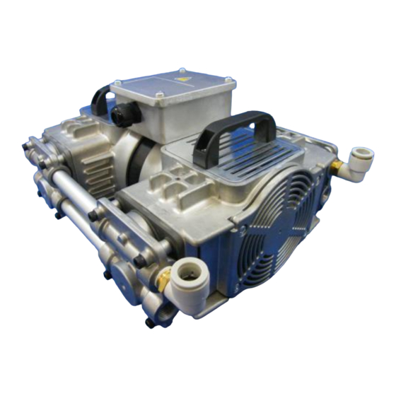
Oscillating Piston Dry Vacuum Pump
DOP-400SB
Request to Users
Please read this manual thoroughly to ensure safe and
effective use of the equipment.
Keep this manual in a safe place.
Due to periodic improvements in performance, the
equipment described in this manual is subject to changes
in dimensions and specifications without prior notice.
ULVAC KIKO, Inc.
Advertisement
Table of Contents

Related Manuals for Ulvac DOP-400SB


Summary of Contents for Ulvac DOP-400SB
- Page 1 Please read this manual thoroughly to ensure safe and effective use of the equipment. Keep this manual in a safe place. Due to periodic improvements in performance, the equipment described in this manual is subject to changes in dimensions and specifications without prior notice. ULVAC KIKO, Inc.
- Page 2 Declaration of Conformity Company:ULVAC KIKO,Inc. Address:291-7 Chausubaru Saito-city,Miyazaki (ZIP Cord:881-0037) Japan. This declaration is issued under the sole responsibility of the manufacturer. In accordance with the following Directive: 2006/42/EC Machinery Directive 2011/65/EU+(EU)2015/863 RoHS Directive declare under our sole responsibility that the product,...
- Page 3 Declaration of Conformity Company:ULVAC KIKO,Inc. Address:291-7 Chausubaru Saito-city,Miyazaki (ZIP Cord:881-0037) Japan. This declaration is issued under the sole responsibility of the manufacturer. In accordance with the following Directive: Supply of Machinery (Safety) Regulations 2008 (S.I. 2008 No. 1597, as amended by S.I. 2019 No. 696) The Restriction of the Use of Certain Hazardous Substances in Electrical and Electronic Equipment Regulations 2012 (S.I.
-
Page 4: Table Of Contents
Contents Pages with a shaded background are those which contain items related to safety. 0.Before Using the Equipment ....................... 01 0.1 Checks When Opening Packaging ..................02 0.2 Using the Pump Safety ....................... 03 ・ Safety symbols ........................03 ・ Cautions for Safety in Use ...................... 04 1. - Page 5 Usage Status Check Sheet ・ Product information, service bases, and contact information Figures and Tables Fig. 2.1 DOP-400SB ........................2 Fig. 3.1 Fluctuations in the power voltage and frequency ............... 4 Fig. 3.2 Example of Piping Used When Evacuating a Vessel ............5 Table 1.1 Product Specifications (50 Hz/60 Hz) ................
-
Page 6: 0.Before Using The Equipment
0.Before Using the Equipment Thank you for purchasing this product. Your custom is very much appreciated. This pump is only for vacuum pumping, and may malfunction or cause accidents if not handled appropriately. Read the manual thoroughly, and pay due attention to inspections, maintenance, and safety. -
Page 7: Checks When Opening Packaging
4. Use ventilation holes, and fit a cooling fan, to reduce the temperature in the vicinity of the pump. Ensure that the pump cooling fan inlet is not blocked. Ensure that a space of at least 100mm is available on all sides of the pump. DOP-400SB... -
Page 8: Using The Pump Safety
Using the Pump Safety 0.2 To ensure that the pump is handled correctly, read this section thoroughly before use. This manual and the warning labels on the pump include safety icons as an aid to understanding safety requirements. These safety icons warn the operator and others of possible dangers and damage and should always be followed. -
Page 9: Cautions For Safety In Use
Cautions for Safety in Use Danger Applications (1) This pump is not designed to be explosion-proof, and should therefore not be used to evacuate explosive gases. (2) In addition to discharge of gas via the pump outlet, gas may leak from the pump itself. Use it only with clean air at normal temperature, or gases of equivalent characteristics. - Page 10 Warning Power Supply (10)When attaching the main power cord to the pump, please use the power cord which meets the rated voltage and current, pursuant to the provision. 4-Core-cable(Size of the wire lead: 1.0m㎡ or larger, 300V or more, 10A or more, 100℃ or higher, one earth cable included) Ensure that one of the core wires is used as an earth wire.
- Page 11 Caution Installation (1) To prevent back injuries, always use at least two people when lifting and moving the pump. (2) Microscopic particles resulting from wear of components are discharged from the outlet and contaminate the room. If necessary, connect a pipe from the discharge outlet to the outside of the building.
- Page 12 Caution Maintenance and Repair (9) If the pump ceases operation, switch off the main power supply immediately to prevent accidents, remove the power cord from the wall outlet, and contact your dealer or the manufacturer for inspection and repair. (10)After stopping the pump, leave it for 30 minutes or more and begin work on it only after checking that it has cooled sufficiently.
-
Page 13: Product Outline
(4) Do not attempt to evacuate gases containing particles, dust, water, or corrosive gases. (5) Do not operate the pump for long periods at near-atmospheric pressure. 1.2 Specifications Table 1.1 Product Specifications (50Hz/60Hz) Model DOP-400SB Evacuate rate (L/min) 400/440 Pressure achieved (kPa) 3φ... -
Page 14: Thermal Protector
Reset temperature 80±10 °C 2) Always fit other protective devices (eg earth leakage breaker, motor breaker) in addition to the overload protection relay. Warning See "Warning" (8) on p.04. See "Caution" (6) on p.06. Caution 2. Dimensions Fig. 2-1 DOP-400SB... -
Page 15: Installation And Storage
3. Installation and Storage 3.1 Cautions for Installation and Storage See "Warning" (1), (2), (3), (5), (6), (7), (8), (9), (10), (11), (12) (13) and(14)on Warning p.04 and 05. See "Caution" (1), (2) (3) and (4) on Caution p.06. Note See "Note"... -
Page 16: Fluctuations In The Power Voltage And Frequency
Caution: Use the power cord which meets the rated voltage and current, pursuant to the provision. Caution: 4-Core-cable(Size of the wire lead: 1.0m㎡ or larger, 300V or more, 10A or more, 100℃ or higher, one earth cable included) The temperature rating of the power cord used must be 100℃ Caution or more. -
Page 17: Storage
4) When evacuating a vessel, ensure that a shut-off valve is placed between the pump inlet pipe and the vessel (see Fig. 3-2). Shut-off valve Vessel Filter Leak valve Vacuum pump Fig. 3-2 Example of Piping Used When Evacuating a Vessel 3.7 Storage Switch off the main power supply and check that the pump has stopped. -
Page 18: Starting In Cold Weather
See "Caution" (6) on p.06. Immediately switch off the main power and contact to the Caution manufacturer, when thermal protector is activated. 4.3 Starting in Cold Weather The bearing grease and cup packing may harden under cold conditions, and the pump may be difficult to start. -
Page 19: Maintenance, Inspection, And Repair
6. Maintenance, Inspection, and Repair 6.1 Cautions for Maintenance, Inspection, and Repair Danger See "Danger" (3) on p.04. See "Warning" (4), (17) and (18) on Warning p.04 and p.05. Caution See "Caution" (9) and (10) on p.07. Note See "Note" (8) on p.07. Customer repair technicians are able to perform the following maintenance and repairs. - Page 20 <Consumables List> Table 6-1 Consumables List (DOP-400SB) Components Quantity Material Average life Cup packing PTFE 6000 Hr valve A type PTFE 6000 Hr valve D type PTFE 6000 Hr valve holder plate A type PTFE 6000 Hr Gaskets EPDM 6000 Hr...
-
Page 21: Replacing Consumables And Cleaning
7. Roctite 242 ※ Wipe components which is contaminated during replacement with 4. And 5. Above. Procedure for Replacing Consumables in DOP-400SB This product is comprised of four head pump chambers. This description includes the procedure for replacing consumables for a single head. It is recommended that the consumables for the remaining three heads are also replaced using this procedure. -
Page 22: Preparations For Replacing The Pump Parts
1) Preparations for Replacing Pump Parts (1) Switch off the pump primary power supply, and remove the piping connected to the inlet pipe. (2) Open the terminal box, and remove the wiring connected to the terminal block. (3) Remove the pump from the equipment. (1)Remove from the equipment. -
Page 23: Removing The Cylinder
(1) Loosen the screws (2) Remove a connection pipe and a head cover. (3) Remove a connection pipe and a head cover. (4) Remove an O-ring attached to a connection pipe. 3) Removing the Cylinder (1) Mark the casing and cylinder with a permanent marker before removing the cylinder. (2) While wearing the gloves, turn the fan slowly upwards. -
Page 24: Removing The Holder Plate And Cup Packing
4) Removing the Holder Plate and Cup Packing. (1) Loosen M8 X L16 belonging to hexagon hole in the holder plate. While wearing gloves, hold the loosened connecting rod and loosen the hexagon whole screws. (2) Remove the holder plate. (3) Remove the cup packing. -
Page 25: Cup Packing Holder Plate Details Parts, Cleaning
6) Cup Packing Holder Plate Details Parts, Cleaning (1) Holder plate and cup packing components list a;Hexagon hole bolt b;Cup packing holder plate c;Cup packing (2) Take the washings to a waste and remove fat neatly Cup packing holder plate particularly Contact department Cup packing. - Page 26 (4) In a cylinder of the gasket pump headpin valve (A) Valve holder plate( A )type attach it in turn. (Only A of the lower photograph follows a valve relief pitcher. As for the valve of the A side, a sunspot comes to the top.) Valve D Valve holder plate A Exhaust...
- Page 27 (7) Installation of the pump head. Pile up a pole of the pump head and hole of the Cylinder. Note) Tighten bolt M6 X L45 belonging to hexagon hole with a torque wrench. Please tighten the clamping torque in the opposite angle, equality in 10N・m. Note) Confirm that it does not seem that a gasket is destroyed seeing from the side.
-
Page 28: Troubleshooting List
6.5 Troubleshooting List Table 6.3 Troubleshooting List Problem Causes Solutions Reference (1) Not connected to power supply. (1) Connect power supply. (2) The main power supply switch is not (2) Set switch to I. (3) Problem with power supply voltage. (3) Ensure that voltage variation is within +/-10%. -
Page 29: In Conclusion
7. In Conclusion Please contact the manufacturer’s sales division if you have any questions. Warranty (1) The warranty for this pump extends for a period of one year from the date of shipment. (2) Any malfunctions or defects which occur under normal usage conditions during the warranty period will be repaired free of charge. -
Page 30: Usage Status Check Sheet
Usage Status Check Sheet (for use in Instruction Manual) * For the purpose of safety control of repair personnel, fill in within the heavy line frame and attach the sheet to the item of which repair is requested. * In case this sheet were not attached or filled in, your request of repair and service may not be accepted. - Page 31 株式会社アルバック 規格品事業部 東日本営業部 〒253-8543 神奈川県茅ヶ崎市萩園2500 TEL:0467-89-2416 株式会社アルバック 規格品事業部 西日本営業部 〒532-0003 大阪府大阪市淀川区宮原3-3-31 上村ニッセイビル5F TEL:06-6397-2286 ULVAC KIKO,Inc. https://ulvac-kiko.com/en Please contact us for products, Service Base or other Inquiries from here. https://showcase.ulvac.co.jp/en/ ULVAC,Inc. Components Division 2500 Hagisono, Chigasaki, Kanagawa, 253-8543, Japan TEL:+81-467-89-2261...
Need help?
Do you have a question about the DOP-400SB and is the answer not in the manual?
Questions and answers