
Related Manuals for Cincoze CO-119C/P1201 Series


Summary of Contents for Cincoze CO-119C/P1201 Series
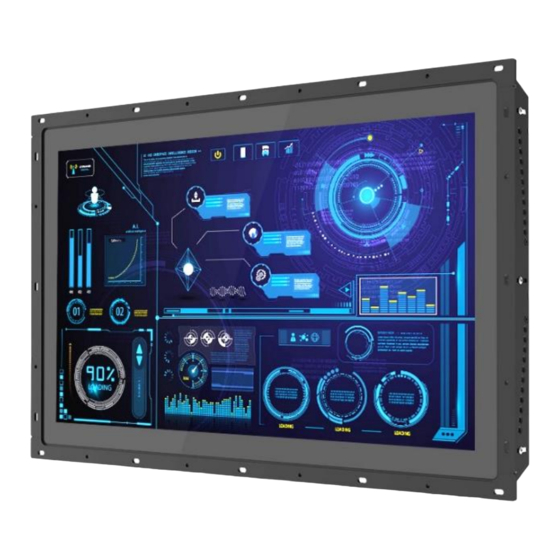
- Page 1 CO-100/P1201 Series User Manual Open Frame Panel PC TFT-LCD Open Frame Display Modular Panel PC with Intel® Elkhart Lake Atom® x6000E Series Processor Version: V1.02...
-
Page 2: Table Of Contents
Chapter 1 Product Introductions ......................11 1.1 Overview ..........................12 1.2 Highlights..........................12 1.3 Key Features ........................... 13 1.4 Hardware Specification ......................14 1.4.1 CO-119C/P1201 Series ....................14 1.4.2 CO-W121C/P1201 Series..................... 18 1.5 System I/O ..........................22 1.5.1 Front ..........................22 1.5.2 Rear ..........................22 1.5.3 Right .......................... - Page 3 3.8 Installing SIM Card ......................... 43 3.9 Disassembling Display Module ....................44 3.10 Installing SATA Hard Drive ....................45 3.11 Installing Standard Mount....................47 3.11.1 Fixing from front side ....................48 3.11.2 Fixing from rear side ....................49 3.12 Installing Flat Mount ......................50 3.12.1 Fixing from front side ....................
- Page 4 6.2.2 CFM-PoE02 ........................88 6.3Installing Accessories ......................90 6.3.1 VESA Mounting ......................90 6.3.2 URM01 ........................91 CO-100/P1201 Series | User Manual...
-
Page 5: Preface
2023/11/30 Copyright Notice © 2023 by Cincoze Co., Ltd. All rights are reserved. No parts of this manual may be copied, modified, or reproduced in any form or by any means for commercial use without the prior written permission of Cincoze Co., Ltd. All information and specification provided in this manual are for reference only and remain subject to change without prior notice. -
Page 6: Declaration Of Conformity
(such as a fuse, battery, etc.), are not warranted. Before sending your product in, you will need to fill in Cincoze RMA Request Form and obtain an RMA number from us. Our staff is available at any time to provide you with the most friendly and immediate service. -
Page 7: Technical Support And Assistance
Limitation of Liability Cincoze’ liability arising out of the manufacture, sale, or supplying of the product and its use, whether based on warranty, contract, negligence, product liability, or otherwise, shall not exceed the original selling price of the product. The remedies provided herein are the customer’s sole and exclusive remedies. -
Page 8: Conventions Used In This Manual
Conventions Used in this Manual This indication alerts operators to an operation that, if not strictly observed, may result in severe injury. (Cette indication avertit les opérateurs d'une opération qui, si elle n'est pas strictement observée, peut entraîner des blessures graves.) This indication alerts operators to an operation that, if not strictly observed, may result in safety hazards to personnel or damage to equipment. - Page 9 13. Never open the equipment. For safety reasons, the equipment should be opened only by qualified service personnel. If one of the following situations arises, get the equipment checked by service personnel: ⚫ The power cord or plug is damaged. ⚫...
-
Page 10: Package Contents
Package Contents Before installation, please ensure all the items listed in the following table are included in the package. Item Description Q’ty CO-100/P1201 Series Panel PC Thermal Pad (for CPU Thermal Block) DIO Terminal Block Connector (Female) Power Terminal Block Connector (Female) Screw Pack Remote Power On/Off Terminal Block Connector Note: Notify your sales representative if any of the above items are missing or damaged. -
Page 11: Chapter 1 Product Introductions
Chapter 1 Product Introductions CO-100/P1201 Series | User Manual... -
Page 12: Overview
1.1 Overview The CO-100/P1201 is an open-frame panel PC with an Intel® Atom® (Elkhart Lake) processor, rich native I/O interfaces (GbE LAN, USB 3.2, COM, and DIO), expansion slots (Mini PCIe and M.2 Key E Type 2230), and CFM (to add PoE and IGN). The major highlight, especially for equipment manufacturers, is the exclusive adjustable mounting bracket (patent pending) that provides thickness adjustment and two panel-locking methods that make installation more convenient and reduce the need for customization during integration. -
Page 13: Key Features
⚫ 1x DDR4 SO-DIMM ⚫ Designed with Adjustable Mounting Bracket ⚫ Support Flat / Standard / VESA / Rack Mount ⚫ Front Panel IP65 Compliant ⚫ Wide Operating Temperature ⚫ Cincoze Patent CDS Technology Support CO-100/P1201 Series | User Manual... -
Page 14: Hardware Specification
1.4 Hardware Specification 1.4.1 CO-119C/P1201 Series Model Name CO-119C Display • 19” (5:4) LCD Size • 1280 x 1024 Resolution • 350 cd/m2 Brightness • 1000:1 Contract Ratio • 16.7M LCD Color • 0.294(H) x 0.294(V) Pixel Pitch • 170 (H) / 160 (V) Viewing Angle •... - Page 15 • EN/IEC 61000-4-6 CS: 3V • EN/IEC 61000-4-8 PFMF: 50 Hz, 1A/m • EN/IEC 61000-4-11 Voltage Dips & Voltage Interruptions: 0.5 cycles at 50 Hz Model Name P1201 System • Intel® Atom® x6425E Processor (1.5M Cache, up to 3.00 GHz, 12W) Processor •...
- Page 16 • 1x CFM PoE Interface for optional CFM-PoE Module Expansion Interface CDS (Convertible Display • 1x CDS Interface for Convertible Display Module System) Interface Other Function • 1x Clear CMOS Switch Clear CMOS Switch • 1x Reset Button Reset Button •...
- Page 17 • UL, cUL, CB, IEC/ EN 62368-1 Safety * Product Specifications and features are for reference only and are subject to change without prior notice. For more information, please refer to the latest product datasheet from Cincoze's website. Dimension CO-119C/P1201...
-
Page 18: Co-W121C/P1201 Series
1.4.2 CO-W121C/P1201 Series Model Name CO-W121C Display • 21.5” (16:9) LCD Size • 1920 x 1080 Resolution • 300 cd/m2 Brightness • 5000:1 Contract Ratio • 16.7M LCD Color • 0.24825(H) x 0.24825(V) mm Pixel Pitch • 178 (H) / 178 (V) Viewing Angle •... - Page 19 • UL, cUL, CB, IEC, EN 62368-1 Safety Model Name P1201 System • Intel® Atom® x6425E Processor (1.5M Cache, up to 3.00 GHz, 12W) Processor • Intel® Atom® x6211E Processor (1.5M Cache, up to 3.00 GHz, 6W) • 1x DDR4 SO-DIMM Socket Memory •...
- Page 20 Other Function • 1x Clear CMOS Switch Clear CMOS Switch • 1x Reset Button Reset Button • Support 0.2sec Instant Reboot Technology Instant Reboot • Software Programmable Supports 256 Levels System Reset Watchdog Timer • LCD On/Off, Brightness Up, Brightness Down OSD Button •...
- Page 21 • UL, cUL, CB, IEC/ EN 62368-1 Safety * Product Specifications and features are for reference only and are subject to change without prior notice. For more information, please refer to the latest product datasheet from Cincoze's website. Dimension CO-W121C/P1201...
-
Page 22: System I/O
1.5 System I/O 1.5.1 Front Antenna Clear CMOS Used to clear CMOS to reset BIOS Used to install an antenna jack Front Accessible 2.5” HDD Tray SIM Card Slot Used to inserts a 2.5” HDD/SSD Used to inserts a SIM card Power LED Reset Switch Indicates the power status of the system... -
Page 23: Right
1.5.3 Right COM3 Mic-In COM port supports RS232/422/485 serial device Used to connect a microphone Line-Out The Digital I/O terminal block supports 4 digital input Used to connect a speaker and 4 digital output Antenna USB 2.0 Used to install an antenna jack Used to connect USB 2.0/1.1 device 1.5.4 Left Temperature LED... -
Page 24: Chapter 2 Switches & Connectors
Chapter 2 Switches & Connectors CO-100/P1201 Series | User Manual... -
Page 25: Location Of Switches And Connectors
2.1 Location of Switches and Connectors 2.1.1 Top View CO-100/P1201 Series | User Manual... -
Page 26: Bottom View
2.1.2 Bottom View CO-100/P1201 Series | User Manual... -
Page 27: Switches And Connectors Definition
2.2 Switches and Connectors Definition Location Definition AT_ATX1 AT / ATX Power Mode Switch CLR_CMOS1 Clear CMOS Switch RESET1 Reset Button BL_UP1 Backlight Brightness Increase Button BL_DN1 Backlight Brightness Decrease Button BL_PWR1 Backlight Power On / Off Button PWR_SW1 Power Switch Super CAP SW PWR_SSD_LED1 Power LED/ HDD LED... -
Page 28: Definition Of Switches
SPK_L1 Speaker Out Connector for left side GDC1 Super CAP for CMOS Backup BAT1 RTC Battery Holder 2.3 Definition of Switches AT_ATX1: AT / ATX Power Mode Switch Switch Definition 1-2 (Right) ATX Power Mode (Default) 2-3 (Left) AT Power Mode PWR_SW1: System Power Button Switch Definition... - Page 29 RESET1: Reset Button Switch Definition Push Reset System SW1: Super CAP SW Location Function DIP1 DIP2 Enabled ON (Default) Super ON (Default) Disabled PWR_SSD_LED1: Power / HDD Access LED Status LED Color Status POWER ON POWER Green HDD Read/Write Blinking Orange LAN1 / LAN2: LAN LED Status Definition Act LED Status Definition...
-
Page 30: Definition Of Connectors
2.4 Definition of Connectors MINIPCIE1 : Mini PCI-Express Socket (mPCIE/ USB3/ SIM Module) Pin No. PIN Name Pin No. Pin name WAKE# +3.3V 1.5V CLKREQ# SIM_VCC SIM_DATA REFCLK‐ SIM_CLK REFCLK+ SIM_Reset UIM_VPP (SIM_VPP) Mechanical Key W_DISABLE# PERST# PERN (USB3RN)/ SATA_RXP +3.3V PERP (USB3RP)/ SATA_RXN +1.5V... - Page 31 M2E_1 : M.2 Key E Connector (Support PCIE type only) Pin No. PIN Name Pin NO. Pin name +3.3V USB_D+ +3.3V USB_D‐ PCM_CLK PCM_SYNC/LPC_RSTN PCM_IN PCM_OUT UART_WAKE# UART_RX/BRI_RSP UARTX/RGI_DT UART_CTS/RGI_RSP PETP0 UART_RTS/BRI_DT PETN0 PERP0 PERN0 REFCLKP0 REFCLKN0 SUSCLK PERST0# CLKREQ0# W_DISABLE2# (PULL‐UP) PEWAKE0# W_DISABLE1# (PULL‐UP)
- Page 32 PEWAKE1# WTCLKN/REFCLKP1 +3.3V WTCLKP/REFCLKN1 +3.3V DC_IN1: DC Power Input Connector (9-48V) Connector Type: Terminal Block 1x3 3-pin, 5.0mm pitch Definition 9-48V IN Ignition (IGN) 1 2 3 Please disconnect the power source before mounting the DC power cables or connecting the DC power connector to system.
- Page 33 COM1_1 / COM2_1 / COM3_1: RS232 / RS422 / RS485 Connector Connector Type: 9-pin D-Sub RS422 / 485 RS485 RS232 Definition Full Duplex Half Duplex Definition Definition DATA - DATA + POWER1: +5V / +12V Power Output Pin 1 Connector Type: 1x4 4-pin Wafer, 2.0mm pitch Definition +12V CO-100/P1201 Series | User Manual...
-
Page 34: Chapter 3 System Setup
Chapter 3 System Setup CO-100/P1201 Series | User Manual... -
Page 35: Removing Top Cover
3.1 Removing Top Cover In order to prevent electric shock or system damage, must turn off power and disconnect the unit from power source before removing the chassis cover. (Afin d'éviter tout risque d'électrocution ou d'endommagement du système, vous devez couper l'alimentation et débrancher l'appareil de la source d'alimentation avant de retirer le couvercle du châssis.) Step 1. -
Page 36: Installing So-Dimm Memory
3.2 Installing SO-DIMM Memory Step 1. Locate the SO-DIMM sockets. Step 2. Tilt the SO-DIMM module at a 45-degree angle and insert it to SO-DIMM socket until the gold-pated connector of module contacted firmly with the socket. 45° Step 3. Press the modules down until it’s fixed firmly by the two locking latches on each side. CO-100/P1201 Series | User Manual... -
Page 37: Installing Mini-Pcie Card
3.3 Installing Mini-PCIe Card (Applicable for full or half size card) Step 1. Locate the Mini PCIe slot. Step 2. Insert the Mini-PCIe card at a 45-degree angle and insert it to the slot until the gold-pated connector of module contacted firmly with the slot. 45°... -
Page 38: Installing M.2 E Key Card
Step 4. If you have a Half-size Mini-PCIe card, make sure use extender to make it Full-size as shown below. 3.4 Installing M.2 E Key Card Step 1. Locate the M.2 E Key slot on the system board. Step 2. Tilt the M.2 E Key card at a 45-degree angle and insert it to the socket until the golden finger connector of the card seated firmly. -
Page 39: Installing Antenna(S)
Step 3. Press the card down and secure it with 1 screw. 3.5 Installing Antenna(s) Please install a mPCIe Wireless Lan card before putting on the washer and fasten the nut to the antenna jack. Step 1. Remove the antenna hole covers at front or side panel. CO-100/P1201 Series | User Manual... - Page 40 Step 2. Have antenna jack penetrate through the hole. Step 3. Put on washer and fasten the nut with antenna jack. Step 4. Assemble the antenna and antenna jack together. CO-100/P1201 Series | User Manual...
-
Page 41: Installing Cpu Thermal Pad
Step 5. Attach the RF connector at another end of cable onto the module. 3.6 Installing CPU Thermal Pad Step 1. Place the thermal pad on the CPU heatsink. thermal pad Before assembling the system’s chassis cover, please make sure the protective film on the Thermal Pad has been removed! (Avant d'assembler le couvercle du châssis du système, assurez-vous que le film protecteur sur le coussin thermique a été... -
Page 42: Installing Top Cover
3.7 Installing Top Cover Step 1. Put on the cover. Step 2. Fasten the 8 screws to fix the cover. CO-100/P1201 Series | User Manual... -
Page 43: Installing Sim Card
3.8 Installing SIM Card Step 1. Loosen 2 screws on front panel to remove cover plate. Step 2. SIM card slot is at the front panel of the system. Step 3. Insert the SIM card. CO-100/P1201 Series | User Manual... -
Page 44: Disassembling Display Module
3.9 Disassembling Display Module The complete shipping product is the CO display module already installed with P1201. This chapter will introduce how to dissemble the CO display module from P1201. Step 1. Remove the 6 screws on the display module. Step 2. -
Page 45: Installing Sata Hard Drive
3.10 Installing SATA Hard Drive Step 1. Loosen 2 screws on front panel to remove cover plate. Step 2. Turn over the unit to have the bottom side face up and loosen 1 screw. Step 3. Pull out the HDD bracket. CO-100/P1201 Series | User Manual... - Page 46 Step 4. Make the bottom side of the HDD face up, place the HDD bracket on it. Ensure the direction of bracket is correct and use 4 provided screws to assemble HDD and HDD bracket together. Step 5. Align the HDD bracket with the entrance of HDD bay. And insert the HDD bracket until the connector of HDD contact the SATA connector firmly.
-
Page 47: Installing Standard Mount
3.11 Installing Standard Mount The CO-100 series currently features two types of Mounting Bracket designs. For example, the Mounting Bracket designs of CO-W121C and CO-119C as illustrated below. CO-W121C CO-119C CO-119C is essentially identical to CO-W121C in terms of installation, with the only difference being the design of the Mounting Bracket. -
Page 48: Fixing From Front Side
Step 1. Put the CO-100/P1201 module onto the rack’s back side. There are two methods for fastening the CO-100/P1201 module onto the cabinet to complete the standard mount. One is to fix the CO-100/P1201 module from the front side of the cabinet, which is illustrated in chapter 3.11.1. -
Page 49: Fixing From Rear Side
3.11.2 Fixing from rear side Step 2. If the cabinet panel is with stud bolts as the following figure, user can prepare 16 pcs of nuts for fixing the module through the oblong holes (oblong hole size: 9mmx4mm, without screw thread). -
Page 50: Installing Flat Mount
3.12 Installing Flat Mount The CO-100 series currently features two types of Mounting Bracket designs. For example, the Mounting Bracket designs of CO-W121C and CO-119C as illustrated below. CO-W121C CO-119C CO-119C is essentially identical to CO-W121C in terms of installation, with the only difference being the design of the Mounting Bracket. - Page 51 Step 3. Loosen the three screws on the left and right-side mounting brackets. Step 4. Measure the rack thickness. The thickness is measured 3mm in this example. Step 5. According to the thickness = 3mm for the example, push down the left and right-side mounting brackets to the place at screw hole = 3mm.
- Page 52 Step 8. Locate the top and bottom-side mounting brackets. Step 9. Remove the two screws on the top and bottom-side mounting brackets. Step 10. Loosen the three screws on the top and bottom-side mounting brackets. Step 11. According to the thickness = 3mm for the example, push down the top and bottom-side mounting brackets to the place at screw hole = 3mm.
- Page 53 Step 12. Fasten the two screws on the top and bottom-side mounting brackets. Step 13. Fasten the three screws on the top and bottom-side mounting brackets. Step 14. Put the CO-100/P1201 module onto the rack back side. There are two methods for fastening the CO-100/P1201 module onto the cabinet to complete the flat mount.
-
Page 54: Fixing From Front Side
3.12.1 Fixing from front side Step 15. Fasten the screws from the cabinet’s front side. Please prepare 12 pcs of M4 screws for fixing the module through the circle holes (with screw thread). 3.12.2 Fixing from rear side Step 15. If the cabinet panel is with stud bolts as the following figure, user can prepare 16 pcs of nuts for fixing the module through the oblong holes (oblong hole size: 9mmx4mm, without screw thread). - Page 55 If the cabinet panel is with bosses as the following figures, user can prepare 16 pcs of M4 screws for fixing the module through the oblong holes (oblong hole size: 9mmx 4mm, without screw thread). CO-100/P1201 Series | User Manual...
-
Page 56: Disassembling Mounting Brackets
3.13 Disassembling Mounting Brackets The CO-100 series currently features two types of Mounting Bracket designs. For example, the Mounting Bracket designs of CO-W121C and CO-119C as illustrated below. CO-W121C CO-119C CO-119C is essentially identical to CO-W121C in terms of installation, with the only difference being the design of the Mounting Bracket. - Page 57 Step 3. Remove the 3 screws on the top and bottom side of mounting brackets. Step 4. Remove the four mounting brackets. CO-100/P1201 Series | User Manual...
-
Page 58: Chapter 4 Bios Setup
Chapter 4 BIOS Setup CO-100/P1201 Series | User Manual... -
Page 59: Bios Introduction
4.1 BIOS Introduction The BIOS (Basic Input/ Output System) is a program located on a Flash Memory on the motherboard. When you start the computer, the BIOS program will gain control. The BIOS first operates an auto-diagnostic test called POST (power on self-test) for all the necessary hardware, it detects the entire hardware device and configures the parameters of the hardware synchronization. -
Page 60: Main Setup
4.2 Main Setup Press <Del> to enter BIOS CMOS Setup Utility, the Main Menu (as shown below) will appears on the screen. Use arrow keys to move among the items and press <Enter> to accept or enter a sub-menu. ◼ System Date Set the date. -
Page 61: Advanced Setup
4.3 Advanced Setup This section allows you to configure and improve your system and allows you to set up some system features according to your preference. 4.3.1 CPU Configuration ◼ Intel Virtualization Technology [Enabled] Enables or disables Intel Virtualization Technology. Virtualization enhanced by Intel Virtualization Technology will allow a platform to run multiple operating systems and applications in independent partitions. -
Page 62: Sata Configuration
4.3.2 SATA Configuration ◼ SATA Controller(s) [Enabled] Enables or disables SATA device. ◼ SATA Mode Selection [AHCI] Allows you to select which mode SATA controller will operates. Configuration options: [AHCI] ❑ Serial ATA Port 0 Port 0 [Enabled] Enables or disables SATA Port 0. ❑... -
Page 63: Trusted Computing Settings
◼ Firmware Update Configuration Configure Management Engine Parameters ❑ Me FW Image Re-Flash [Disabled] Enables or disables ME firmware Image Re-Flash function. 4.3.4 Trusted Computing Settings ◼ Security Device Support [Enabled] Enables or disables Security Device Support function. ◼ SHA256 PCR Bank [Enabled] Enables or disables SHA256 PCR Bank function. -
Page 64: Acpi Settings
4.3.5 ACPI Settings ◼ Enable Hibernation [Enabled] Enables or disables system ability to hibernate state (OS/S4 state). This option may not be effective with some OS. ◼ ACPI Sleep State [S3 (Suspend to RAM)] Allows users to select the highest Advanced Configuration Power Interface® (ACPI) sleep state that system will enter when suspend button is pressed. - Page 65 ◼ Serial Port 1~3 Configuration. ❑ Serial Port [Enabled] Enables or disables serial port. ❑ Change Settings [Auto] Allows you to change the IO Address & IRQ settings of the specified serial port. ❑ Serial Port Mode [RS232] Allows you to select Serial Port Mode. Configuration options: [RS232] [RS422/RS485 Full Duplex] [RS485 Half Duplex] ◼...
-
Page 66: Hardware Monitor
4.3.7 Hardware Monitor This screen displays the current status of all monitored hardware devices/components such as voltages, temperatures. 4.3.8 S5 RTC Wake Settings ◼ Wake system from S5 [Disabled] Enables or disables wake system from S5 (soft-off state). [Disabled]: Disables wake system from S5. [Fixed Time]: Sets a fixed time (HH:MM:SS) to wake system from S5. -
Page 67: Serial Port Console Redirection
4.3.9 Serial Port Console Redirection ◼ Console Redirection [Disabled] Allow users to enable or disable COM1, COM2, COM3 console redirection function. 4.3.10 USB Configuration ◼ XHCI Hand-off [Enabled] Enables or disables XHCI (USB3.0) hand-off function. Use this feature as a workaround for operating systems without XHCI hand-off support. -
Page 68: Network Stack Configuration
4.3.11 Network Stack Configuration ◼ Network Stack [Disabled] Enables or disables UEFI Network Stack. CO-100/P1201 Series | User Manual... -
Page 69: Chipset Setup
4.4 Chipset Setup This section allows you to configure chipset related settings according to user’s preference. 4.4.1 System Agent (SA) Configuration ◼ Memory Configuration This item displays detailed memory configuration in the system. ◼ Graphics Configuration ❑ Primary Display [Auto] Allows users to enable or disable Primary Display Configuration options: [Auto] [IGFX] [PCIe] ❑... -
Page 70: Pch-Io Configuration
Enables or disables Intel® Virtualization Technology for Directed I/O (VT-d) capability. 4.4.2 PCH-IO Configuration ◼ PCI Express Configuration ❑ PCI Express Root Port (MINIPCIE1) ◼ PCI Express Root Port [Enabled] Enables or disables PCI Express Root Port. ◼ PCIe Speed [Auto] Allows you to select PCI Express interface speed. - Page 71 Configuration options: [Auto] [Gen1] [Gen2] [Gen3]. ❑ PCI Express Root Port (M2E_1 2X1) ◼ PCI Express Root Port [Enabled] Enables or disables PCI Express Root Port. ◼ PCIe Speed [Auto] Allows you to select PCI Express interface speed. Configuration options: [Auto] [Gen1] [Gen2] [Gen3]. ◼...
-
Page 72: Security Setup
4.5 Security Setup This section allows users to configure BIOS security settings. ◼ Administrator Password Administrator Password controls access to the BIOS Setup utility. ◼ User Password User Password controls access to the system at boot and to the BIOS Setup utility. ◼... -
Page 73: Boot Setup
4.6 Boot Setup This section allows you to configure Boot settings. ◼ Setup Prompt Timeout [1] Use this item to set number of seconds (1..65535) to wait for setup activation key. ◼ Bootup NumLock State Allows you to set NumLock key to [On] or [Off] state when system boots up. ◼... -
Page 74: Save & Exit
4.7 Save & Exit ◼ Save Changes and Exit This item allows you to exit the system after saving changes. ◼ Discard Changes and Exit This item allows you to exit system setup without saving any changes. ◼ Save Changes and Reset This item allows you to reset the system after saving changes. -
Page 75: Chapter 5 Product Application
Chapter 5 Product Application CO-100/P1201 Series | User Manual... -
Page 76: Digital I/O (Dio) Application
5.1 Digital I/O (DIO) application This section describes DIO application of the product. The content and application development are better understood and implemented by well experienced professionals or developers. 5.1.1 Digital I/O Programming Guide 5.1.1.1 Pins for Digital I/O 1~8 Item Standard GPIO 74 (PIN 107) - Page 77 CO-100/P1201 Series | User Manual...
- Page 78 GPIO access way by Digital I/O (Access GPIO data register Only) GPIO access way by Coniguration register port (Access 0x4E/0x4F port with device number 0x06) CO-100/P1201 Series | User Manual...
- Page 79 CO-100/P1201 Series | User Manual...
- Page 80 5.1.1.4 Sample Code in C Language This sample code is demonstrate how to access GPIO by the way of Configuration Register port. 5.1.1.4.1 Control of GP74 to GP77 (DI1~DI4) #define AddrPort 0x4E #define DataPort 0x4F <Enter the Extended Function Mode> WriteByte(AddrPort, 0x87) WriteByte(AddrPort, 0x87) // Must write twice to enter extended mode...
- Page 81 // Select configuration register 60h (High Byte address) WriteByte(DataPort, (0x0A)) WriteByte(AddrPort, 0x61) // Select configuration register 61h (Low Byte address) WriteByte(DataPort, (0x00)) <Leave the Extended Function Mode> WriteByte(AddrPort, 0xAA) Note: Cincoze default DIO Port base address is 0xA00h CO-100/P1201 Series | User Manual...
- Page 82 5.1.1.6 DATA Bit Table (GPIO) =DI1 =DO1 value value (Base address +3) (Base address +2) (0xA03) (0xA02) =DI2 =DO2 value value (Base address +3) (Base address +2) (0xA03) (0xA02) =DI3 =DO3 value value (Base address +3) (Base address +2) (0xA03) (0xA02) =DI4 =DO4...
-
Page 83: Digital I/O (Dio) Hardware Specification
5.2 Digital I/O (DIO) Hardware Specification ⚫ XCOM+: Isolated power in V+ ⚫ XCOM-: Isolated power in V- ⚫ Isolated power in DC voltage: 9-30V ⚫ 4x Digital Input (Source Type) ⚫ Input Signal Voltage Level Signal Logic 0: XCOM+ = 9V, Signal Low <... - Page 84 CO-100/P1201 Series | User Manual...
-
Page 85: Chapter 6 Optional Modules And Accessories
Chapter 6 Optional Modules and Accessories CO-100/P1201 Series | User Manual... -
Page 86: Pin Definition & Settings
6.1 Pin Definition & Settings 6.1.1 CFM-IGN101 SW2: IGN Function Switch Set shutdown delay timer when ACC is turned off Pin 1 Pin 2 Pin 3 Pin 4 Definition 0 second 1 minute 5 minutes 10 minutes ON (IGN Enabled) 30 minutes OFF (IGN Disabled) 1 hour... -
Page 87: Installing Cfm Modules
6.2 Installing CFM Modules 6.2.1 CFM-IGN101 Step 1. Locate the IGN connector on system motherboard as indicated. Step 2. Insert CFM-IGN module vertically to the female connector on the system’s mainboard, and fasten 2 screws to fix it. Step 3. Loosen 2 screws on front panel to remove cover plate. Step 4. -
Page 88: Cfm-Poe02
6.2.2 CFM-PoE02 Step 1. Locate the PoE connector on system motherboard as indicated. Step 2. Insert the female connector of CFM-PoE module to the male connector on system motherboard. Step 3. Turn over the heatsink and paste the thermal pad onto the marked by red squares. Before putting on the thermal block (in the next step), please make sure the protective film on the Thermal Pad has been removed! (Avant de mettre le bloc thermique (à... - Page 89 Step 4. Paste the heatsink onto the CFM-PoE module carefully and fasten 2 screws to fix it. Step 5. Paste the thermal pads onto the heatsink and coil carefully. Before assembling the system’s chassis cover, please make sure the protective film on the Thermal Pad has been removed! (Avant d'assembler le couvercle du châssis du système, assurez-vous que le film protecteur sur le coussin thermique a été...
-
Page 90: Installing Accessories
6.3 Installing Accessories 6.3.1 VESA Mounting The following picture indicates VESA mounting hole pattern on P1201 series, which is compliant with VESA mounting standard. Step 1. Please fasten the VESA screws as indicated to fix it on the stand. CO-100/P1201 Series | User Manual... -
Page 91: Urm01
6.3.2 URM01 Before the installation of rack mount, user need to follow the previous chapter to disassemble the mounting brackets on the CO display module first. Step 1. Locate the screw holes on the PC or monitor module. Step 2. Put on the rack mount base and fasten the screws. CO-100/P1201 Series | User Manual... - Page 92 Step 3. Assemble two rack mount brackets by fastening 4 screws (M5x6) at each side. Rack mount bracket holes for 19”~21.5” Panel PC series For P2002E For P2002/P1001E For P1001/P1101/ P1201/P2102/ P2102E/P2202/P2202E Left Right Bottom Step 4. Assemble two rack mount brackets by fastening 4 screws (M5x12), flat washers and hex nuts at each side.
- Page 93 © 2023 Cincoze Co., Ltd. All rights reserved. The Cincoze logo is a registered trademark of Cincoze Co., Ltd. All other logos appearing in this catalog are the intellectual property of the respective company, product, or organization associated with the logo.
Need help?
Do you have a question about the CO-119C/P1201 Series and is the answer not in the manual?
Questions and answers