
Related Manuals for Cincoze CO-100 Series


Summary of Contents for Cincoze CO-100 Series
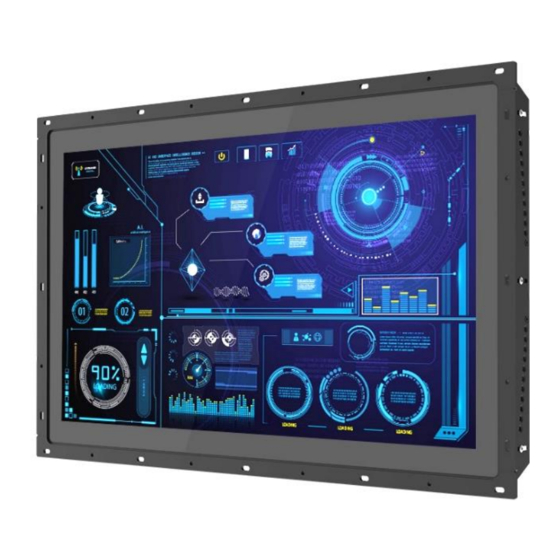
- Page 1 CO-100 Series User Manual Open Frame Panel TFT-LCD Open Frame Display Module Version: V1.00...
-
Page 2: Table Of Contents
Contents Preface ..........................3 Copyright Notice ........................3 Acknowledgement .........................3 Disclaimer ..........................3 Declaration of Conformity ......................4 Product Warranty Statement ....................4 Technical Support and Assistance ..................6 Conventions Used in this Manual ..................6 Safety Precautions.........................7 Package Contents .........................8 Ordering Information ......................8 Chapter 1 Product Introductions ....................9 1.1 Overview ........................ -
Page 3: Preface
2022/09/05 Copyright Notice © 2022 by Cincoze Co., Ltd. All rights are reserved. No parts of this manual may be copied, modified, or reproduced in any form or by any means for commercial use without the prior written permission of Cincoze Co., Ltd. All information and specification provided in this manual are for reference only and remain subject to change without prior notice. -
Page 4: Declaration Of Conformity
Product Warranty Statement Warranty Cincoze products are warranted by Cincoze Co., Ltd. to be free from defect in materials and workmanship for 2 years (2 Years for PC Module, 1 Year for Display Module) from the date of purchase by the original purchaser. During the warranty period, we shall, at our option, either repair or replace any product that proves to be defective under normal operation. - Page 5 Limitation of Liability Cincoze’ liability arising out of the manufacture, sale, or supplying of the product and its use, whether based on warranty, contract, negligence, product liability, or otherwise, shall not exceed the original selling price of the product. The remedies provided herein are the customer’s sole and exclusive remedies.
-
Page 6: Technical Support And Assistance
Technical Support and Assistance 1. Visit the Cincoze website at www.cincoze.com where you can find the latest information about the product. 2. Contact your distributor or our technical support team or sales representative for technical support if you need additional assistance. Please have following information ready before you call: ⚫... -
Page 7: Safety Precautions
Safety Precautions Before installing and using this device, please note the following precautions. Read these safety instructions carefully. Keep this User’s Manual for future reference. Disconnected this equipment from any AC outlet before cleaning. For plug-in equipment, the power outlet socket must be located near the equipment and must be easily accessible. -
Page 8: Package Contents
Package Contents Before installation, please ensure all the items listed in the following table are included in the package. CO-W121C-R10 Item Description Q’ty CO-W121C Display Module Note: Notify your sales representative if any of the above items are missing or damaged. Ordering Information Display Module with Projected Capacitive Touch Model No. -
Page 9: Chapter 1 Product Introductions
Chapter 1 Product Introductions Series | User Manual CO-100... -
Page 10: Overview
1.1 Overview Cincoze open frame display modules (CO-W121C) use our patented CDS (Convertible Display System) technology to connect with a computer module (P2000 or P1000 series) to form an industrial panel PC or connect with a monitor module (M1100 series) to form an industrial touch monitor. -
Page 11: Key Features
Strong, Reliable and Durable The CO-100 series integrated structure design enables wide temperature support (0–70°C) in addition to front IP65 dustproof and waterproof protection, meeting HMI application requirements. 0 – 70°C IP65 Highly Adaptable CDS Design Through the patented CDS technology, theCO-100 can... -
Page 12: Hardware Specification
1.4 Hardware Specification 1.4.1 CO-W121C-R10 Display • 21.5” (16:9) LCD Size • 1920 x 1080 Resolution • 300 cd/m2 Brightness • 5000:1 Contract Ratio • 16.7M LCD Color • 0.24825(H) x 0.24825(V) mm Pixel Pitch • 178 (H) / 178 (V) Viewing Angle •... - Page 13 • 80% RH @ 40°C (non-condensing) Humidity • CE, UKCA, FCC, ICES-003 Class A • UL, cUL 62368-1 (Pending) Safety External Layout Dimension Unit: mm Series | User Manual CO-100...
-
Page 14: Chapter 2 System Setup
Chapter 2 System Setup Series | User Manual CO-100... -
Page 15: Connecting To Pc Or Monitor Module
2.1 Connecting to PC or Monitor Module 1. Locate the male connector on the display module and the female connector on the PC or monitor module. (Please assemble the wall mount brackets and remove the CDS cover plate on the PC or monitor module first according to its user manual.) PC module Monitor module 2. - Page 16 3. Fasten the 6 screws to fix the PC module or monitor module on the display module. Series | User Manual CO-100...
-
Page 17: Standard Mount
2.2 Standard Mount Before doing the following steps, please make sure the screw positions are fastened at the default positions as indicated in the following picture. The default positions are the correct positions for Standard Mount, so it does not need to change the screw positions additionally for Standard Mount. - Page 18 2. Fasten the screws from the rack’s front side. Please prepare 12 x M4 screws for fixing the module through the screw holes as shown below. User can also prepare 16 x M4 screws for fixing the module through the oblong holes as shown below.
-
Page 19: Flat Mount
2.3 Flat Mount 1. Locate the left and right-side mounting brackets. 2. Remove the two screws on the left and right-side mounting brackets. 3. Loosen the three screws on the left and right-side mounting brackets. 4. Measure the rack thickness. The thickness is measured 3mm in this example. Series | User Manual CO-100... - Page 20 5. According to the thickness = 3mm for the example, push down the left and right-side mounting brackets to the place at screw hole = 3mm. 6. Fasten the two screws on the left and right-side mounting brackets. 7. Fasten the three screws on the left and right-side mounting brackets. Series | User Manual CO-100...
- Page 21 8. Locate the top and bottom-side mounting brackets. 9. Remove the two screws on the top and bottom-side mounting brackets. Series | User Manual CO-100...
- Page 22 10. Loosen the three screws on the both side’s mounting brackets. 11. According to the thickness = 3mm for the example, push down the top and bottom-side mounting brackets to the place at screw hole = 3mm. 12. Fasten the two screws on the top and bottom-side mounting brackets. 13.
- Page 23 14. Put the CO-100 module onto the rack back side. 15. Fasten the screws from the rack’s front side. Please prepare 12 x M4 screws for fixing the module through the screw holes as shown below. (The screw length is according to your rack thickness) Series | User Manual CO-100...
- Page 24 User can also prepare 16 x M4 screws for fixing the module through the oblong holes as shown below. Series | User Manual CO-100...
- Page 25 © 2022 Cincoze Co., Ltd. All rights reserved. The Cincoze logo is a registered trademark of Cincoze Co., Ltd. All other logos appearing in this catalog are the intellectual property of the respective company, product, or organization associated with the logo.
Need help?
Do you have a question about the CO-100 Series and is the answer not in the manual?
Questions and answers