
Related Manuals for Cincoze CO-119C-R10


Summary of Contents for Cincoze CO-119C-R10
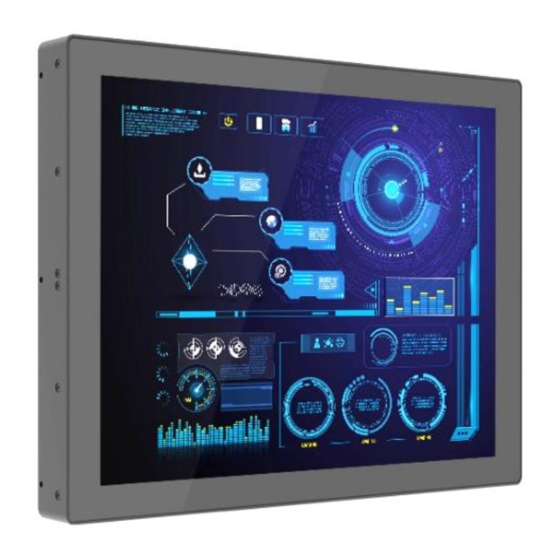
- Page 1 CO-100 Series User Manual Open Frame Panel TFT-LCD Open Frame Display Module Version: V1.03...
-
Page 2: Table Of Contents
1.1 Overview ..........................10 1.2 Highlights..........................10 1.3 Key Features ........................... 11 1.4 Hardware Specification ......................12 1.4.1 CO-119C-R10 ..........................12 1.4.2 CO-W121C-R10 .......................... 14 Chapter 2 System Setup ........................16 2.1 Connecting to PC or Monitor Module ..................17 2.2 Standard Mount ........................ -
Page 3: Preface
2024/01/30 Copyright Notice © 2022 by Cincoze Co., Ltd. All rights are reserved. No parts of this manual may be copied, modified, or reproduced in any form or by any means for commercial use without the prior written permission of Cincoze Co., Ltd. All information and specification provided in this manual are for reference only and remain subject to change without prior notice. - Page 4 (such as a fuse, battery, etc.), are not warranted. Before sending your product in, you will need to fill in Cincoze RMA Request Form and obtain an RMA number from us. Our staff is available at any time to provide you with the most friendly and immediate service.
- Page 5 Limitation of Liability Cincoze’ liability arising out of the manufacture, sale, or supplying of the product and its use, whether based on warranty, contract, negligence, product liability, or otherwise, shall not exceed the original selling price of the product. The remedies provided herein are the customer’s sole and exclusive remedies.
- Page 6 Conventions Used in this Manual This indication alerts operators to an operation that, if not strictly observed, may result in severe injury. (Cette indication avertit les opérateurs d'une opération qui, si elle n'est pas strictement observée, peut entraîner des blessures graves.) This indication alerts operators to an operation that, if not strictly observed, may result in safety hazards to personnel or damage to equipment.
- Page 7 17. Dispose of used battery promptly. Keep away from children. Do not disassemble and do not dispose of in fire. Package Contents Before installation, please ensure all the items listed in the following table are included in the package. CO-119C-R10 Item Description Q’ty CO-119C Display Module Note: Notify your sales representative if any of the above items are missing or damaged.
- Page 8 Ordering Information Display Module with Projected Capacitive Touch Model No. Product Description 19“TFT-LCD SXGA 5:4 Open Frame Display Module with CO-119C-R10 Projected Capacitive Touch 21.5" TFT-LCD Full HD 16:9 Open Frame Display Module with CO-W121C-R10 Projected Capacitive Touch CO-100 Series | User Manual...
-
Page 9: Chapter 1 Product Introductions
Chapter 1 Product Introductions CO-100 Series | User Manual... -
Page 10: Overview
1.1 Overview Cincoze open frame display modules (CO-100) use our patented CDS (Convertible Display System) technology to connect with a computer module (P2000 or P1000 series) to form an industrial panel PC or connect with a monitor module (M1100 series) to form an industrial touch monitor. Designed for equipment manufacturers, easy installation is the main advantage of the CO-100. -
Page 11: Key Features
Patent No. M482908 1.3 Key Features ⚫ TFT-LCD with Projected Capacitive Touch ⚫ Cincoze Patent CDS Technology Support ⚫ Designed with Adjustable Mounting Bracket ⚫ Support Flat / Standard / VESA / Rack Mount ⚫... -
Page 12: Hardware Specification
• 80% RH @ 50°C (non-condensing) Humidity * Product Specifications and features are for reference only and are subject to change without prior notice. For more information, please refer to the latest product datasheet from Cincoze's website. CO-100 Series | User Manual... - Page 13 External Layout Dimension Unit: mm CO-100 Series | User Manual...
-
Page 14: Co-W121C-R10
• UL, cUL, CB, IEC, EN 62368-1 Safety * Product Specifications and features are for reference only and are subject to change without prior notice. For more information, please refer to the latest product datasheet from Cincoze's website. CO-100 Series | User Manual... - Page 15 External Layout Dimension Unit: mm CO-100 Series | User Manual...
-
Page 16: Chapter 2 System Setup
Chapter 2 System Setup CO-100 Series | User Manual... -
Page 17: Connecting To Pc Or Monitor Module
2.1 Connecting to PC or Monitor Module In order to prevent electric shock or system damage, must turn off power and disconnect the unit from power source before removing the chassis cover. (Afin d'éviter tout risque d'électrocution ou d'endommagement du système, vous devez couper l'alimentation et débrancher l'appareil de la source d'alimentation avant de retirer le couvercle du châssis.) Step 1. - Page 18 Step 2. Connect the modules. Step 3. Fasten the 6 screws to fix the PC module or monitor module on the display module. CO-100 Series | User Manual...
-
Page 19: Standard Mount
2.2 Standard Mount The CO-100 series currently features two types of Mounting Bracket designs. For example, the Mounting Bracket designs of CO-W121C and CO-119C as illustrated below. CO-W121C CO-119C CO-119C is essentially identical to CO-W121C in terms of installation, with the only difference being the design of the Mounting Bracket. -
Page 20: Fixing From Front Side
Step 1. Put the CO-100 module onto the cabinet’s back side. There are two methods for fastening the CO-100 module onto the cabinet to complete the standard mount. One is to fix the CO-100 module from the front side of the cabinet, which is illustrated in chapter 2.2.1. -
Page 21: Fixing From Rear Side
2.2.2 Fixing from rear side Step 2. If the cabinet panel is with stud bolts as the following figure, user can prepare 16 pcs of nuts for fixing the module through the oblong holes (oblong hole size: 9mmx4mm, without screw thread). If the cabinet panel is with bosses as the following figures, user can prepare 16 pcs of M4 screws for fixing the module through the oblong holes (oblong hole size: 9mmx 4mm, without screw thread). -
Page 22: Flat Mount
2.3 Flat Mount The CO-100 series currently features two types of Mounting Bracket designs. For example, the Mounting Bracket designs of CO-W121C and CO-119C as illustrated below. CO-W121C CO-119C CO-119C is essentially identical to CO-W121C in terms of installation, with the only difference being the design of the Mounting Bracket. - Page 23 Step 2. Remove the two screws on the left and right-side mounting brackets. Step 3. Loosen the three screws on the left and right-side mounting brackets. Step 4. Measure the rack thickness. The thickness is measured 3mm in this example. CO-100 Series | User Manual...
- Page 24 Step 5. According to the thickness = 3mm for the example, push down the left and right-side mounting brackets to the place at screw hole = 3mm. Step 6. Fasten the two screws on the left and right-side mounting brackets. Step 7.
- Page 25 Step 8. Locate the top and bottom-side mounting brackets. Step 9. Remove the two screws on the top and bottom-side mounting brackets. Step 10. Loosen the three screws on the both side’s mounting brackets. CO-100 Series | User Manual...
- Page 26 Step 11. According to the thickness = 3mm for the example, push down the top and bottom-side mounting brackets to the place at screw hole = 3mm. Step 12. Fasten the two screws on the top and bottom-side mounting brackets. Step 13.
-
Page 27: Fixing From Front Side
Step 14. Put the CO-100 module onto the cabinet back side. There are two methods for fastening the CO-100 module onto the cabinet to complete the flat mount. One is to fix the CO-100 module from the front side of the cabinet, which is illustrated in chapter 2.3.1. The other one is to fix the CO-100 module from the rear side of the cabinet, which is illustrated in chapter 2.3.2. -
Page 28: Fixing From Rear Side
2.3.2 Fixing from rear side Step 15. If the cabinet panel is with stud bolts as the following figure, user can prepare 16 pcs of nuts for fixing the module through the oblong holes (oblong hole size: 9mmx4mm, without screw thread). If the cabinet panel is with bosses as the following figures, user can prepare 16 pcs of M4 screws for fixing the module through the oblong holes (oblong hole size: 9mmx 4mm, without screw thread). - Page 29 © 2023 Cincoze Co., Ltd. All rights reserved. The Cincoze logo is a registered trademark of Cincoze Co., Ltd. All other logos appearing in this catalog are the intellectual property of the respective company, product, or organization associated with the logo.
Need help?
Do you have a question about the CO-119C-R10 and is the answer not in the manual?
Questions and answers