
Related Manuals for Cincoze CV-100/P1201 Series


Summary of Contents for Cincoze CV-100/P1201 Series
- Page 1 CV-100/P1201 Series User Manual Power Efficient Industrial Panel PC 8.4”~24” TFT LCD Panel PC with Intel® Elkhart Lake Atom® x6000E Series Processor Version: V1.00...
-
Page 2: Table Of Contents
Chapter 2 Switches & Connectors ......................70 2.1 Location of Switches and Connectors ..................71 2.1.1 Top View ........................71 2.1.2 Bottom View ....................... 72 2.2 Switches and Connectors Definition ..................73 2.3 Definition of Switches ......................74 CV-100/P1201 Series | User Manual... - Page 3 5.1.1 Digital I/O Programming Guide ................. 115 5.2 Digital I/O (DIO) Hardware Specification ................122 5.2.1 DIO Connector Definition ..................122 Chapter 6 Optional Modules and Accessories ................... 124 6.1 Pin Definition & Settings ...................... 125 CV-100/P1201 Series | User Manual...
- Page 4 6.1.1 CFM-IGN101 ......................125 6.2 Installing CFM Modules ......................126 6.2.1 CFM-IGN101 ......................126 6.2.2 CFM-PoE02 ........................ 127 6.3 Installing Accessories ......................129 6.3.1 VESA Mounting ......................129 6.3.2 URM01 ........................130 CV-100/P1201 Series | User Manual...
-
Page 5: Preface
2023/03/31 Copyright Notice © 2023 by Cincoze Co., Ltd. All rights are reserved. No parts of this manual may be copied, modified, or reproduced in any form or by any means for commercial use without the prior written permission of Cincoze Co., Ltd. All information and specification provided in this manual are for reference only and remain subject to change without prior notice. -
Page 6: Declaration Of Conformity
(such as a fuse, battery, etc.), are not warranted. Before sending your product in, you will need to fill in Cincoze RMA Request Form and obtain an RMA number from us. Our staff is available at any time to provide you with the most friendly and immediate service. -
Page 7: Technical Support And Assistance
Limitation of Liability Cincoze’ liability arising out of the manufacture, sale, or supplying of the product and its use, whether based on warranty, contract, negligence, product liability, or otherwise, shall not exceed the original selling price of the product. The remedies provided herein are the customer’s sole and exclusive remedies. -
Page 8: Conventions Used In This Manual
11. If the equipment is not used for a long time, disconnect it from the power source to avoid damage by transient overvoltage. 12. Never pour any liquid into an opening. This may cause fire or electrical shock. CV-100/P1201 Series | User Manual... - Page 9 9-48 VDC, minimum 6-1.5A, with minimum rated maximum ambient temperature 70°C, and has to be evaluated according to UL/IEC/EN 60950-1 and/or UL/IEC/EN 62368-1. If need further assistance, please contact Cincoze for further information. 17. Ensure to connect the power cord of power adapter to a socket-outlet with earthing connection.
-
Page 10: Package Contents
10.4" TFT-LCD SVGA 4:3 Panel PC with Intel Atom x6211E CV-110R-R10/P1201-X6211E-R10 Dual Core Processor and Resistive 5-wire Touch 10.4" TFT-LCD SVGA 4:3 Panel PC with Intel Atom x6211E CV-110C-R11/P1201-X6211E-R10 Dual Core Processor and P-Cap. Touch CV-100/P1201 Series | User Manual... - Page 11 17" TFT-LCD SXGA 5:4 Panel PC with Intel Atom x6425E CV-117G-R10/P1201-X6425E-R10 Quad Core Processor and without Touch 17" TFT-LCD SXGA 5:4 Panel PC with Intel Atom x6211E CV-117R-R10/P1201-X6211E-R10 Dual Core Processor and Resistive 5-wire Touch CV-100/P1201 Series | User Manual...
- Page 12 21.5" TFT-LCD Full HD 16:9 Panel PC with Intel Atom CV-W121G-R10/P1201-X6425E-R10 x6425E Quad Core Processor and without Touch 21.5" TFT-LCD Full HD 16:9 Panel PC with Intel Atom CV-W121R-R10/P1201-X6211E-R10 x6211E Dual Core Processor and Resistive 5-wire Touch CV-100/P1201 Series | User Manual...
- Page 13 24" TFT-LCD Full HD 16:9 Panel PC with Intel Atom x6211E CV-W124C-R11/P1201-X6211E-R10 Dual Core Processor and P-Cap. Touch 24" TFT-LCD Full HD 16:9 Panel PC with Intel Atom x6211E CV-W124G-R10/P1201-X6211E-R10 Dual Core Processor and without Touch CV-100/P1201 Series | User Manual...
-
Page 14: Chapter 1 Product Introductions
Chapter 1 Product Introductions CV-100/P1201 Series | User Manual... -
Page 15: Overview
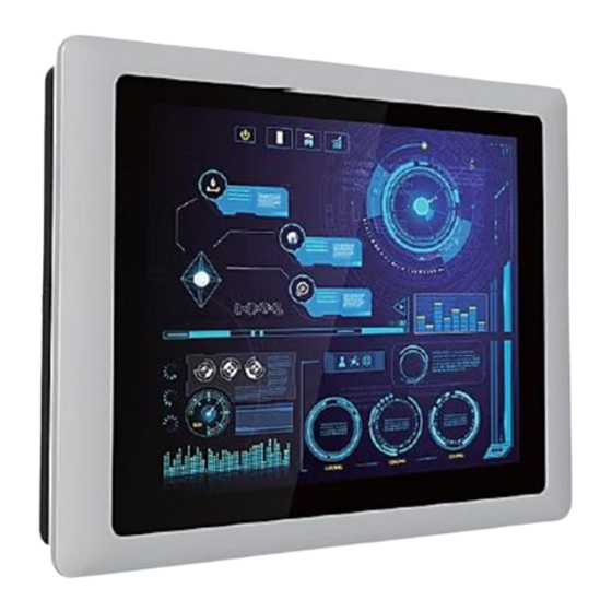
1.1 Overview The CV-100/P1201 series is a modular industrial panel PC with an Intel® Atom® (Elkhart Lake) processor. Available in a selection of screen sizes, the CV-100/P1201 has flexible expansion options, including rich native I/O interfaces (GbE LAN, USB 3.2, COM, and DIO), Mini PCIe and M.2 Key E Type 2230 expansion slots, and exclusive CFM expansion to add functions such as PoE and IGN. -
Page 16: Key Features
⚫ 1x DDR4 SO-DIMM ⚫ Designed with Rugged Aluminum Die-casting Front Bezel ⚫ Support Panel / VESA / Rack Mount ⚫ Front Panel IP65 Compliant ⚫ Wide Operating Temperature ⚫ Cincoze Patent CDS Technology Support CV-100/P1201 Series | User Manual... -
Page 17: Hardware Specification
• -20°C to 70°C (with Industrial Grade peripherals; Ambient with air flow) Operating Temperature • • Storage Temperature -30°C to 80°C -20°C to 70°C • • Relative Humidity 80% RH @ 50°C (Non-condensing) 85% RH @ 50°C (Non-condensing) • CE, UKCA, FCC, ICES-003 Class A CV-100/P1201 Series | User Manual... - Page 18 • 1x CFM IGN Interface for optional CFM-IGN Module Expansion CFM (Control Function Module) • 1x CFM PoE Interface for optional CFM-PoE Module Expansion Interface CDS (Convertible Display • 1x CDS Interface for Convertible Display Module System) Interface CV-100/P1201 Series | User Manual...
- Page 19 • Protection Type: shut down operating voltage, re-power on at the present level to recover • 15A Over Current Protection • SuperCap Integrated for CMOS Battery Maintenance-free Operation CMOS Battery Backup • 283,091 Hours - Database: Telcordia SR-332 Issue3, Method 1, Case 3 MTBF CV-100/P1201 Series | User Manual...
- Page 20 • UL, cUL, CB, IEC/ EN 62368-1 Safety * Product Specifications and features are for reference only and are subject to change without prior notice. For more information, please refer to the latest product datasheet from Cincoze's website. CV-100/P1201 Series | User Manual...
- Page 21 Dimension CV-108/P1201 Unit: mm CV-100/P1201 Series | User Manual...
-
Page 22: Cv-110/P1201 Series
• Ambient with Air flow: -10°C to 70°C (with Industrial Grade Peripherals) (with Industrial Grade Peripherals) • Storage Temperature -30°C to 80°C • Relative Humidity 80% RH @ 40°C (Non-condensing) • CE, UKCA, FCC, ICES-003 Class A CV-100/P1201 Series | User Manual... - Page 23 • 1x CFM IGN Interface for optional CFM-IGN Module Expansion CFM (Control Function Module) • 1x CFM PoE Interface for optional CFM-PoE Module Expansion Interface CDS (Convertible Display • 1x CDS Interface for Convertible Display Module System) Interface CV-100/P1201 Series | User Manual...
- Page 24 • Protection Type: shut down operating voltage, re-power on at the present level to recover • 15A Over Current Protection • SuperCap Integrated for CMOS Battery Maintenance-free Operation CMOS Battery Backup • 283,091 Hours - Database: Telcordia SR-332 Issue3, Method 1, Case 3 MTBF CV-100/P1201 Series | User Manual...
- Page 25 • UL, cUL, CB, IEC/ EN 62368-1 Safety * Product Specifications and features are for reference only and are subject to change without prior notice. For more information, please refer to the latest product datasheet from Cincoze's website. CV-100/P1201 Series | User Manual...
- Page 26 Dimension CV-110/P1201 Unit: mm CV-100/P1201 Series | User Manual...
-
Page 27: Cv-110H/P1201 Series
• Ambient with Air flow: -10°C to 70°C (with Industrial Grade Peripherals) (with Industrial Grade Peripherals) • Storage Temperature -30°C to 80°C • Relative Humidity 80% RH @ 40°C (Non-condensing) • CE, UKCA, FCC, ICES-003 Class A CV-100/P1201 Series | User Manual... - Page 28 • 1x CFM IGN Interface for optional CFM-IGN Module Expansion CFM (Control Function Module) • 1x CFM PoE Interface for optional CFM-PoE Module Expansion Interface CDS (Convertible Display • 1x CDS Interface for Convertible Display Module System) Interface CV-100/P1201 Series | User Manual...
- Page 29 • Protection Type: shut down operating voltage, re-power on at the present level to recover • 15A Over Current Protection • SuperCap Integrated for CMOS Battery Maintenance-free Operation CMOS Battery Backup • 283,091 Hours - Database: Telcordia SR-332 Issue3, Method 1, Case 3 MTBF CV-100/P1201 Series | User Manual...
- Page 30 • UL, cUL, CB, IEC/ EN 62368-1 Safety * Product Specifications and features are for reference only and are subject to change without prior notice. For more information, please refer to the latest product datasheet from Cincoze's website. CV-100/P1201 Series | User Manual...
- Page 31 Dimension CV-110H/P1201 Unit: mm CV-100/P1201 Series | User Manual...
-
Page 32: Cv-112H/P1201 Series
• Ambient with Air flow: -20°C to 80°C (with Industrial Grade Peripherals) (with Industrial Grade Peripherals) • Storage Temperature -30°C to 80°C • Relative Humidity 80% RH @ 40°C (Non-condensing) • CE, UKCA, FCC, ICES-003 Class A CV-100/P1201 Series | User Manual... - Page 33 • 1x CFM IGN Interface for optional CFM-IGN Module Expansion CFM (Control Function Module) • 1x CFM PoE Interface for optional CFM-PoE Module Expansion Interface CDS (Convertible Display • 1x CDS Interface for Convertible Display Module System) Interface CV-100/P1201 Series | User Manual...
- Page 34 • Protection Type: shut down operating voltage, re-power on at the present level to recover • 15A Over Current Protection • SuperCap Integrated for CMOS Battery Maintenance-free Operation CMOS Battery Backup • 283,091 Hours - Database: Telcordia SR-332 Issue3, Method 1, Case 3 MTBF CV-100/P1201 Series | User Manual...
- Page 35 • UL, cUL, CB, IEC/ EN 62368-1 Safety * Product Specifications and features are for reference only and are subject to change without prior notice. For more information, please refer to the latest product datasheet from Cincoze's website. CV-100/P1201 Series | User Manual...
- Page 36 Dimension CV-112H/P1201 Unit: mm CV-100/P1201 Series | User Manual...
-
Page 37: Cv-115/P1201 Series
• Ambient with Air flow: 0°C to 65°C (with Industrial Grade Peripherals) Operating Temperature • -20°C to 65°C Storage Temperature • Relative Humidity 80% RH @ 40°C (Non-condensing) • CE, UKCA, FCC, ICES-003 Class A CV-100/P1201 Series | User Manual... - Page 38 • 1x CFM IGN Interface for optional CFM-IGN Module Expansion CFM (Control Function Module) • 1x CFM PoE Interface for optional CFM-PoE Module Expansion Interface CDS (Convertible Display • 1x CDS Interface for Convertible Display Module System) Interface CV-100/P1201 Series | User Manual...
- Page 39 • Protection Type: shut down operating voltage, re-power on at the present level to recover • 15A Over Current Protection • SuperCap Integrated for CMOS Battery Maintenance-free Operation CMOS Battery Backup • 283,091 Hours - Database: Telcordia SR-332 Issue3, Method 1, Case 3 MTBF CV-100/P1201 Series | User Manual...
- Page 40 • UL, cUL, CB, IEC/ EN 62368-1 Safety * Product Specifications and features are for reference only and are subject to change without prior notice. For more information, please refer to the latest product datasheet from Cincoze's website. CV-100/P1201 Series | User Manual...
- Page 41 Dimension CV-115/P1201 Unit: mm CV-100/P1201 Series | User Manual...
-
Page 42: Cv-W115/P1201 Series
Operating Temperature • Ambient with Air flow: 0°C to 60°C (with Industrial Grade Peripherals) • -20°C to 60°C Storage Temperature • Relative Humidity 80% RH @ 40°C (Non-condensing) • CE, UKCA, FCC, ICES-003 Class A CV-100/P1201 Series | User Manual... - Page 43 • 1x CFM IGN Interface for optional CFM-IGN Module Expansion CFM (Control Function Module) • 1x CFM PoE Interface for optional CFM-PoE Module Expansion Interface CDS (Convertible Display • 1x CDS Interface for Convertible Display Module System) Interface CV-100/P1201 Series | User Manual...
- Page 44 • Protection Type: shut down operating voltage, re-power on at the present level to recover • 15A Over Current Protection • SuperCap Integrated for CMOS Battery Maintenance-free Operation CMOS Battery Backup • 283,091 Hours - Database: Telcordia SR-332 Issue3, Method 1, Case 3 MTBF CV-100/P1201 Series | User Manual...
- Page 45 • UL, cUL, CB, IEC/ EN 62368-1 Safety * Product Specifications and features are for reference only and are subject to change without prior notice. For more information, please refer to the latest product datasheet from Cincoze's website. CV-100/P1201 Series | User Manual...
- Page 46 Dimension CV-W115/P1201 Unit: mm CV-100/P1201 Series | User Manual...
-
Page 47: Cv-117/P1201 Series
-20°C to 80°C (with Industrial -30°C to 85°C (with Industrial Grade Peripherals) Grade Peripherals) Grade Peripherals) • Storage Temperature -30°C to 80°C • Relative Humidity 80% RH @ 40°C (Non-condensing) • CE, UKCA, FCC, ICES-003 Class A CV-100/P1201 Series | User Manual... - Page 48 • 1x CFM IGN Interface for optional CFM-IGN Module Expansion CFM (Control Function Module) • 1x CFM PoE Interface for optional CFM-PoE Module Expansion Interface CDS (Convertible Display • 1x CDS Interface for Convertible Display Module System) Interface CV-100/P1201 Series | User Manual...
- Page 49 • Protection Type: shut down operating voltage, re-power on at the present level to recover • 15A Over Current Protection • SuperCap Integrated for CMOS Battery Maintenance-free Operation CMOS Battery Backup • 283,091 Hours - Database: Telcordia SR-332 Issue3, Method 1, Case 3 MTBF CV-100/P1201 Series | User Manual...
- Page 50 • UL, cUL, CB, IEC/ EN 62368-1 Safety * Product Specifications and features are for reference only and are subject to change without prior notice. For more information, please refer to the latest product datasheet from Cincoze's website. CV-100/P1201 Series | User Manual...
- Page 51 Dimension CV-117/P1201 Unit: mm CV-100/P1201 Series | User Manual...
-
Page 52: Cv-119/P1201 Series
• Ambient with Air flow: 0°C to 50°C (with Industrial Grade Peripherals) Storage Temperature • -20°C to 60°C Relative Humidity • 80% RH @ 50°C (Non-condensing) • CE, UKCA, FCC, ICES-003 Class A • Safety UL, cUL, CB CV-100/P1201 Series | User Manual... - Page 53 • 1x CFM IGN Interface for optional CFM-IGN Module Expansion CFM (Control Function Module) • 1x CFM PoE Interface for optional CFM-PoE Module Expansion Interface CDS (Convertible Display • 1x CDS Interface for Convertible Display Module System) Interface CV-100/P1201 Series | User Manual...
- Page 54 • Protection Type: shut down operating voltage, re-power on at the present level to recover • 15A Over Current Protection • SuperCap Integrated for CMOS Battery Maintenance-free Operation CMOS Battery Backup • 283,091 Hours - Database: Telcordia SR-332 Issue3, Method 1, Case 3 MTBF CV-100/P1201 Series | User Manual...
- Page 55 • UL, cUL, CB, IEC/ EN 62368-1 Safety * Product Specifications and features are for reference only and are subject to change without prior notice. For more information, please refer to the latest product datasheet from Cincoze's website. CV-100/P1201 Series | User Manual...
- Page 56 Dimension CV-119/P1201 Unit: mm CV-100/P1201 Series | User Manual...
-
Page 57: Cv-W121/P1201 Series
• Ambient with Air flow: 0°C to 60°C (with Industrial Grade Peripherals) Storage Temperature • -20°C to 60°C Relative Humidity • 80% RH @ 40°C (Non-condensing) • CE, UKCA, FCC, ICES-003 Class A • Safety UL, cUL, CB CV-100/P1201 Series | User Manual... - Page 58 • 1x CFM IGN Interface for optional CFM-IGN Module Expansion CFM (Control Function Module) • 1x CFM PoE Interface for optional CFM-PoE Module Expansion Interface CDS (Convertible Display • 1x CDS Interface for Convertible Display Module System) Interface CV-100/P1201 Series | User Manual...
- Page 59 • Protection Type: shut down operating voltage, re-power on at the present level to recover • 15A Over Current Protection • SuperCap Integrated for CMOS Battery Maintenance-free Operation CMOS Battery Backup • 283,091 Hours - Database: Telcordia SR-332 Issue3, Method 1, Case 3 MTBF CV-100/P1201 Series | User Manual...
- Page 60 • UL, cUL, CB, IEC/ EN 62368-1 Safety * Product Specifications and features are for reference only and are subject to change without prior notice. For more information, please refer to the latest product datasheet from Cincoze's website. CV-100/P1201 Series | User Manual...
- Page 61 Dimension CV-W121/P1201 Unit: mm CV-100/P1201 Series | User Manual...
-
Page 62: Cv-W124/P1201 Series
• 80% RH @ 50°C (Non-condensing) Vibration • -- • Operating, 1 Grms, 10-500 • -- Hz, 3 Axes (w/ P2102E only, according to IEC60068-2-6) • CE, UKCA, FCC, ICES-003 Class A • UL, cUL, CB Safety • -- CV-100/P1201 Series | User Manual... - Page 63 • 1x CFM IGN Interface for optional CFM-IGN Module Expansion CFM (Control Function Module) • 1x CFM PoE Interface for optional CFM-PoE Module Expansion Interface CDS (Convertible Display • 1x CDS Interface for Convertible Display Module System) Interface CV-100/P1201 Series | User Manual...
- Page 64 • Protection Type: shut down operating voltage, re-power on at the present level to recover • 15A Over Current Protection • SuperCap Integrated for CMOS Battery Maintenance-free Operation CMOS Battery Backup • 283,091 Hours - Database: Telcordia SR-332 Issue3, Method 1, Case 3 MTBF CV-100/P1201 Series | User Manual...
- Page 65 • UL, cUL, CB, IEC/ EN 62368-1 Safety * Product Specifications and features are for reference only and are subject to change without prior notice. For more information, please refer to the latest product datasheet from Cincoze's website. CV-100/P1201 Series | User Manual...
- Page 66 Dimension CV-W124/P1201 Unit: mm CV-100/P1201 Series | User Manual...
-
Page 67: System I/O
LAN1, LAN2 Used to plug a remote power on/off terminal block Used to connect the system to a local area network Remote Power LED A terminal block used to connect to remote power on/off LED CV-100/P1201 Series | User Manual... -
Page 68: Right
Press to increase brightness of the screen devices Decrease Brightness Press to decrease brightness of the screen Used to connect to the earth ground to prevent LCD On/Off electrical shock Press to turn-on or turn-off the display CV-100/P1201 Series | User Manual... -
Page 69: Top
1.5.5 Top VESA Mounting Hole These are mounting holes for VESA mount (75x75mm and 100x100mm) CV-100/P1201 Series | User Manual... -
Page 70: Chapter 2 Switches & Connectors
Chapter 2 Switches & Connectors CV-100/P1201 Series | User Manual... -
Page 71: Location Of Switches And Connectors
2.1 Location of Switches and Connectors 2.1.1 Top View CV-100/P1201 Series | User Manual... -
Page 72: Bottom View
2.1.2 Bottom View CV-100/P1201 Series | User Manual... -
Page 73: Switches And Connectors Definition
Remote Power Button/ Remote LED Connector Power1 +5V / +12V Power Output SATA1 SATA Connector POE_PH1 POE Board to Board Connector SODIMM1 DDR4 SODIMM Slot SIM1 SIM Card socket SPK_R1 Speaker Out Connector for right side CV-100/P1201 Series | User Manual... -
Page 74: Definition Of Switches
BL_PWR1: Backlight Power on / off Switch Definition Push Backlight Power on / off switching BL_UP1: Backlight Brightness Increase Switch Definition Push Backlight Brightness Increase BL_DN1: Backlight Brightness Decrease Switch Definition Push Backlight Brightness Decrease CV-100/P1201 Series | User Manual... - Page 75 1Gbps Network Link Orange 100Mbps Network Link 10Mbps Network Link TEMP_LED1: Main Board Temperature LED Status LED Status Status Main Board Temp ≤ 60°C Blue 60°C < Main Board Temp ≤ 87°C 87°C ≤ Main Board Temp CV-100/P1201 Series | User Manual...
-
Page 76: Definition Of Connectors
SIM_VCC SIM_DATA REFCLK‐ SIM_CLK REFCLK+ SIM_Reset UIM_VPP (SIM_VPP) Mechanical Key W_DISABLE# PERST# PERN (USB3RN)/ SATA_RXP +3.3V PERP (USB3RP)/ SATA_RXN +1.5V SMB_CLK PETN (USB3TN)/ SATA_TXN SMB_DATA PETP (USB3TP)/ SATA_TXP USB_D‐ USB_D+ +3VSB_MPCIE_FB +3VSB_MPCIE_FB +1.5V W_DISABLE2# +3.3V CV-100/P1201 Series | User Manual... - Page 77 +3.3V USB_D+ +3.3V USB_D‐ PCM_CLK PCM_SYNC/LPC_RSTN PCM_IN PCM_OUT UART_WAKE# UART_RX/BRI_RSP UARTX/RGI_DT UART_CTS/RGI_RSP PETP0 UART_RTS/BRI_DT PETN0 PERP0 PERN0 REFCLKP0 REFCLKN0 SUSCLK PERST0# CLKREQ0# W_DISABLE2# (PULL‐UP) PEWAKE0# W_DISABLE1# (PULL‐UP) I2C_DATA WTD1N/PETP1 I2C_CLK WTD1P/PETN1 WT_D0N/PERP1 PERST1# WT_D0P/PERN1 CLKREQ1# CV-100/P1201 Series | User Manual...
- Page 78 Remote Power Button Remote Power LED Do not apply power to this connector! This port is used to connect a SWITCH! (Ne mettez pas sous tension ce connecteur! Ce port est utilisé pour connecter un SWITCH!) CV-100/P1201 Series | User Manual...
- Page 79 Connector Type: 9-pin D-Sub RS422 / 485 RS485 RS232 Definition Full Duplex Half Duplex Definition Definition DATA - DATA + POWER1: +5V / +12V Power Output Pin 1 Connector Type: 1x4 4-pin Wafer, 2.0mm pitch Definition +12V CV-100/P1201 Series | User Manual...
-
Page 80: Chapter 3 System Setup
Chapter 3 System Setup CV-100/P1201 Series | User Manual... -
Page 81: Removing Top Cover
1. Loosen the 8 screws of front and rear panel, then place them aside. 2. Remove the cover from the chassis. 3. Place the top cover gently. CV-100/P1201 Series | User Manual... -
Page 82: Installing So-Dimm Memory
2. Tilt the SO-DIMM module at a 45-degree angle and insert it to SO-DIMM socket until the gold-pated connector of module contacted firmly with the socket. 45° 3. Press the modules down until it’s fixed firmly by the two locking latches on each side. CV-100/P1201 Series | User Manual... -
Page 83: Installing Mini-Pcie Card
Insert the Mini-PCIe card at a 45-degree angle and insert it to the slot until the gold-pated connector of module contacted firmly with the slot. 45° Press down the module and fasten two screws to secure the module. CV-100/P1201 Series | User Manual... -
Page 84: Installing M.2 E Key Card
1. Locate the M.2 E Key slot on the system board. 2. Tilt the M.2 E Key card at a 45-degree angle and insert it to the socket until the golden finger connector of the card seated firmly. 45° CV-100/P1201 Series | User Manual... -
Page 85: Installing Antenna
3. Press the card down and secure it with 1 screw. 3.5 Installing Antenna Please install a mPCIe Wireless Lan card before putting on the washer and fasten the nut to the antenna jack. 1. Remove the antenna hole covers at front or side panel. CV-100/P1201 Series | User Manual... - Page 86 2. Have antenna jack penetrate through the hole. 3. Put on washer and fasten the nut with antenna jack. 4. Assemble the antenna and antenna jack together. CV-100/P1201 Series | User Manual...
-
Page 87: Installing Cpu Thermal Pad
Before assembling the system’s chassis cover, please make sure the protective film on the Thermal Pad has been removed! (Avant d'assembler le couvercle du châssis du système, assurez-vous que le film protecteur sur le coussin thermique a été retiré !d'alimentation CC au système.) CV-100/P1201 Series | User Manual... -
Page 88: Installing Top Cover
3.7 Installing Top Cover 1. Put on the cover. 2. Fasten the 8 screws to fix the cover. CV-100/P1201 Series | User Manual... -
Page 89: Installing Sim Card
Installing SIM Card 1. Loosen 2 screws on front panel to remove cover plate. 2. SIM card slot is at the front panel of the system. 3. Insert the SIM card. CV-100/P1201 Series | User Manual... -
Page 90: Disassembling Display Module
The complete shipping product is the CV display module already installed with P1201. This chapter will introduce how to dissemble the CV display module from P1201. 1. Remove the 6 screws on the display module. 2. Disconnect the modules. CV-100/P1201 Series | User Manual... -
Page 91: Installing Sata Hard Drive
3.10 Installing SATA Hard Drive 1. Loosen 2 screws on front panel to remove cover plate. 2. Turn over the unit to have the bottom side face up and loosen 1 screw. 3. Pull out the HDD bracket. CV-100/P1201 Series | User Manual... - Page 92 5. Align the HDD bracket with the entrance of HDD bay. And insert the HDD bracket until the connector of HDD contact the SATA connector firmly. 6. Turn over the unit to have the bottom side face up and fasten the screw. CV-100/P1201 Series | User Manual...
-
Page 93: Installing Panel Mount
3.11 Installing Panel Mount 1. Accessories provided by Cincoze are as below. Before assembly, please prepare panel mount PPC and customer’s fixture. CV-100/P1201 Series | User Manual... - Page 94 2. All mounting kits displayed are to be inserted into holes. 3. Installation preparation and steps. CV-100/P1201 Series | User Manual...
- Page 95 CV-100/P1201 Series | User Manual...
- Page 96 4. Apply all mount kits to the rest of holes. And you have completed the panel mount installation, as shown below. CV-100/P1201 Series | User Manual...
-
Page 97: Chapter 4 Bios Setup
Chapter 4 BIOS Setup CV-100/P1201 Series | User Manual... -
Page 98: Bios Introduction
( ↑↓ ) to highlight the field and press <Enter> to call up the sub-menu. Then you can use the control keys to enter values and move from field to field within a sub-menu. If you want to return to the main menu, just press the <Esc >. CV-100/P1201 Series | User Manual... -
Page 99: Main Setup
Use arrow keys to move among the items and press <Enter> to accept or enter a sub-menu. ◼ System Date Set the date. Please use <Tab> to switch between date elements. ◼ System Time Set the time. Please use <Tab> to switch between time elements. CV-100/P1201 Series | User Manual... -
Page 100: Advanced Setup
Technology will allow a platform to run multiple operating systems and applications in independent partitions. With virtualization, one computer system can function as multiple virtual systems. ◼ Active Processor Cores [All] Number of cores to enable in each processor package. CV-100/P1201 Series | User Manual... -
Page 101: Sata Configuration
Allows you to select which mode SATA controller will operates. Configuration options: [AHCI] ❑ Serial ATA Port 0 Port 0 [Enabled] Enables or disables SATA Port 0. ❑ Serial ATA Port 1 Port 1 [Enabled] Enables or disables SATA Port 1. 4.3.3 PCH-FW Configuration CV-100/P1201 Series | User Manual... -
Page 102: Trusted Computing Settings
Enables or disables Storage Hierarchy function. ◼ Endorsement Hierarchy [Enabled] Enables or disables Endorsement Hierarchy function. ◼ Physical Presence Spec Version [1.3] Allows you to select which mode Physical Presence Spec Version will operate. Configuration options: [1.2], [1.3] CV-100/P1201 Series | User Manual... -
Page 103: Acpi Settings
[S3 (suspend to RAM)]: Enables suspend to RAM state. 4.3.6 F81966 Super IO Configuration Set Parameters of Serial Ports. User can Enable/Disable the serial port and Select an optimal setting for the Super IO Device. CV-100/P1201 Series | User Manual... - Page 104 Configuration options: [RS232] [RS422/RS485 Full Duplex] [RS485 Half Duplex] ◼ Watch Dog Mode [Sec] Allows to set watchdog timer unit <Sec> or <Min>. ◼ Watch Dog Timer [0] Allows you to set watchdog timer’s value in the range of 0 to 255. CV-100/P1201 Series | User Manual...
-
Page 105: Hardware Monitor
Enables or disables wake system from S5 (soft-off state). [Disabled]: Disables wake system from S5. [Fixed Time]: Sets a fixed time (HH:MM:SS) to wake system from S5. [Dynamic Time]: Sets an increase minute(s) from current time to wake system from S5. CV-100/P1201 Series | User Manual... -
Page 106: Serial Port Console Redirection
Enables or disables XHCI (USB3.0) hand-off function. Use this feature as a workaround for operating systems without XHCI hand-off support. ◼ USB Mass Storage Driver Support [Enabled] Enables or disables USB mass storage driver support. CV-100/P1201 Series | User Manual... -
Page 107: Network Stack Configuration
4.3.11 Network Stack Configuration ◼ Network Stack [Disabled] Enables or disables UEFI Network Stack. CV-100/P1201 Series | User Manual... -
Page 108: Chipset Setup
❑ Primary Display [Auto] Allows users to enable or disable Primary Display Configuration options: [Auto] [IGFX] [PCIe] ❑ Internal Graphics [Auto] Allows users to enable or disable Internal Graphics. Configuration options: [Auto] [Disabled] [Enabled] ◼ VT-d [Enabled] CV-100/P1201 Series | User Manual... -
Page 109: Pch-Io Configuration
Configuration options: [Auto] [Gen1] [Gen2] [Gen3]. ❑ PCI Express Root Port (M2E_1) ◼ PCI Express Root Port [Enabled] Enables or disables PCI Express Root Port. ◼ PCIe Speed [Auto] Allows you to select PCI Express interface speed. CV-100/P1201 Series | User Manual... - Page 110 Allows you to specify which power state system will enter when power is resumed after a power failure (G3 state). [Always on]: Enters to power on state. [Always off]: Enters to power off state. [Keep last state]: Enters to the last power state before a power failure. CV-100/P1201 Series | User Manual...
-
Page 111: Security Setup
User Password controls access to the system at boot and to the BIOS Setup utility. ◼ Security Boot ❑ Secure Boot [Disabled] Enable or disable Secure Boot function. ❑ Secure Boot Mode [Standard] Allows you to select Secure Boor Mode. Configuration options: [Standard] [Custom]. CV-100/P1201 Series | User Manual... -
Page 112: Boot Setup
Allows you to enable or disable Quiet Boot function. ◼ Fast Boot Allows you to enable or disable Fast Boot function. If enabled, system boots with initialization of a minimal set of devices required to launch active boot option. CV-100/P1201 Series | User Manual... -
Page 113: Save & Exit
Save as User Defaults This item allows you to save the changes done so far as user defaults. ◼ Restore User Defaults This item allows you to restore the user defaults to all the setup options. CV-100/P1201 Series | User Manual... -
Page 114: Chapter 5 Product Application
Chapter 5 Product Application CV-100/P1201 Series | User Manual... -
Page 115: Digital I/O (Dio) Application
0xAA to the index port. Following is an example to enable configuration and to disable configuration by using debug. -o 4E 87 -o 4E 87 (enable configuration) -o 4E AA (disable configuration) 5.1.1.3 Relative Registers To program the F81966D configuration registers, see the following configuration procedures. CV-100/P1201 Series | User Manual... - Page 116 CV-100/P1201 Series | User Manual...
- Page 117 GPIO access way by Digital I/O (Access GPIO data register Only) GPIO access way by Coniguration register port (Access 0x4E/0x4F port with device number 0x06) CV-100/P1201 Series | User Manual...
- Page 118 CV-100/P1201 Series | User Manual...
- Page 119 // Must write twice to enter extended mode <Select Logic Device> WriteByte(AddrPort, 0x07) WriteByte(DataPort, 0x06) // Select logic device 06h <Output/Input Mode Selection> // Set GP80 to GP83 output mode WriteByte(AddrPort, 0x88) // Select configuration register 88h CV-100/P1201 Series | User Manual...
- Page 120 // Select configuration register 60h (High Byte address) WriteByte(DataPort, (0x0A)) WriteByte(AddrPort, 0x61) // Select configuration register 61h (Low Byte address) WriteByte(DataPort, (0x00)) <Leave the Extended Function Mode> WriteByte(AddrPort, 0xAA) Note: Cincoze default DIO Port base address is 0xA00h CV-100/P1201 Series | User Manual...
- Page 121 =DI4 =DO4 value value (Base address +3) (Base address +2) (0xA03) (0xA02) 5.1.1.7 DIO I/O Port Address (Default Address 0xA00) Pin Definition Data Bits DIO Type Digital Input Digital Output I/O Port Address 0xA03 0xA02 CV-100/P1201 Series | User Manual...
-
Page 122: Digital I/O (Dio) Hardware Specification
Signal High Level: Pull up resistor to XCOM+ Signal Low Level: = XCOM- Sink Current: 1A (Max) 5.2.1 DIO Connector Definition DIO1: Digital Input / Output Connector Connector Type: Terminal Block 1X10 10-pin, 3.5mm pitch Definition Definition XCOM+ (DC INPUT) XCOM- (GND) CV-100/P1201 Series | User Manual... - Page 123 CV-100/P1201 Series | User Manual...
-
Page 124: Chapter 6 Optional Modules And Accessories
Chapter 6 Optional Modules and Accessories CV-100/P1201 Series | User Manual... -
Page 125: Pin Definition & Settings
5 minutes 10 minutes ON (IGN Enabled) 30 minutes OFF (IGN Disabled) 1 hour 2 hours Reserved (0 second) 24V_12V_1: 12V / 24V Car Battery Switch Definition 24V Car Battery Input (default) 12V Car Battery Input CV-100/P1201 Series | User Manual... -
Page 126: Installing Cfm Modules
2. Insert CFM-IGN module vertically to the female connector on the system’s mainboard, and fasten 2 screws to fix it. 3. Loosen 2 screws on front panel to remove cover plate. 4. IGN function switch is at the front panel of the system. CV-100/P1201 Series | User Manual... -
Page 127: Cfm-Poe02
Before putting on the thermal block (in the next step), please make sure the protective film on the Thermal Pad has been removed! (Avant de mettre le bloc thermique (à l'étape suivante), veuillez vous assurer que le film protecteur sur le coussin thermique a été retiré!) CV-100/P1201 Series | User Manual... - Page 128 (Avant d'assembler le couvercle du châssis du système, assurez-vous que le film protecteur sur le coussin thermique a été retiré !d'alimentation CC au système.) 6. When the system is power on, please note that the POE LED will light on if the POE module is properly installed. CV-100/P1201 Series | User Manual...
-
Page 129: Installing Accessories
6.3.1 VESA Mounting The following picture indicates VESA mounting hole pattern on P1201 series, which is compliant with VESA mounting standard. 1. Please fasten the VESA screws as indicated to fix it on the stand. CV-100/P1201 Series | User Manual... -
Page 130: Urm01
2. Put on the rack mount base and fasten the screws. 3. Locate the Rack mount bracket holes. For P2002E For P2002/P1001E For P1001/P1101/P1201/P2102/P2102E For 8.4” ~ 17” Panel PC series For P1001/P1101/P1201/P2102/ P2102E For P2002/P1001E For P2002E For 19” ~ 24” Panel PC series CV-100/P1201 Series | User Manual... - Page 131 4. Assemble two rack mount brackets by fastening 4 screws (M5x6) at each side. Left view Right view Bottom view For 8.4” ~ 17” Panel PC series Left view Right view Bottom view For 19” ~ 24” Panel PC series CV-100/P1201 Series | User Manual...
- Page 132 5. Assemble two rack mount brackets by fastening 4 screws (M5x12), flat washers and hex nuts at each side. For 8.4” ~ 17” Panel PC series For 19” ~ 24” Panel PC series CV-100/P1201 Series | User Manual...
- Page 133 © 2023 Cincoze Co., Ltd. All rights reserved. The Cincoze logo is a registered trademark of Cincoze Co., Ltd. All other logos appearing in this catalog are the intellectual property of the respective company, product, or organization associated with the logo.
Need help?
Do you have a question about the CV-100/P1201 Series and is the answer not in the manual?
Questions and answers