
Related Manuals for Seiko SII SLP721RT


Summary of Contents for Seiko SII SLP721RT
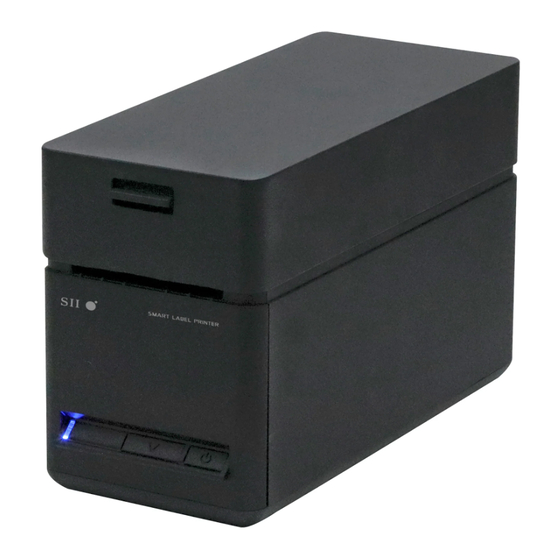
- Page 1 USER'S GUIDE Thermal Printer SLP720RT SERIES Read this USER'S GUIDE carefully before using the printer. Keep this USER'S GUIDE in a place where it can be accessed quickly.
- Page 2 (including consequential) caused by reliance on the materials presented, including but not limited to typographical, arithmetic, and listing errors. This product is developed as a product for industrial equipment use. is a trademark of Seiko Instruments Inc. Android is a trademark of Google LLC.
- Page 3 Product: AC adapter PW-H2415-W1 Directive: Title 2014/30/EU EC Electromagnetic Compatibility Directive 2014/35/EU EC Low Voltage Directive 2009/125/EC Directive on Eco-Design of Energy-related Products 2011/65/EU (Commission Delegated Directive (EU) 2015/863) Restriction of the use of certain hazardous substances (RoHS) Directive Standards EN 55032 EN IEC 61000-3-2 EN 61000-3-3...
- Page 4 Connect the equipment into an outlet on a circuit different from that to which the receiver is connected. Consult the dealer or an experienced radio/TV technician for help. Changes or modifications not expressly approved by Seiko Instruments could void the user's authority to operate the equipment.
-
Page 5: Table Of Contents
1. INTRODUCTION This manual describes how to handle SLP720RT series thermal printer (hereinafter referred to as printer), AC adapter and AC cable. Read through "2. SAFETY PRECAUTIONS" and "3. OPERATING PRECAUTIONS" carefully before using the products, and handle them safely and properly. Keep this manual in a place where it can be accessed quickly. -
Page 6: Safety Precautions
2. SAFETY PRECAUTIONS In this SAFETY PRECAUTIONS, the following symbols are used to ensure safe and proper use of products and prevent from damaging devices. WARNING Failure to follow the instructions marked with this symbol could result in severe personal injury or death. CAUTION Failure to follow the instructions marked with this symbol could result in minor personal injury or property damage. - Page 7 OPERATING PRECAUTIONS The "products" shall collectively mean the printer, the AC adapter and the AC cable. WARNING Never attempt the following. Failure to follow the instructions leads to fire, electric shock, or accident. DO NOT insert any foreign objects such as a piece of metal or any liquid into the products. DO NOT touch the terminals of the products, power connector, AC plug, and DC plug.
- Page 8 Procedures to take when in trouble Follow the instructions in the following cases. Failure to follow the instructions may lead fire, electric shock, or accident. Turn off the printer, and unplug the AC plug from the outlet in any of the following cases: Abnormal status continues.
-
Page 9: Operating Precautions
3. OPERATING PRECAUTIONS Be careful of the following precautions and use the products properly in order to deliver and maintain the full performance of the products. ■ Using Products Precautions for use environment Be careful not to drop or bump the products on a hard surface. ◆... - Page 10 The AC adapter may get a little hot when in use. This is normal and not a malfunction. ◆ Always use the specified thermal paper. See "16 ACCESSORIES AND CONSUMABLE PARTS" for ◆ details. DO NOT touch the thermal head directly. Doing so may result in poor printing quality due to the dirt ◆...
- Page 11 Precautions for storing Turn off the printer when not in use. ◆ In addition, when the printer is not used for a long time, unplug the AC cable from the outlet. Moreover, set thermal paper to protect the platen. ■ Thermal Paper Handling Store the thermal paper in a cool, dry, and dark place.
-
Page 12: Preparation
4. PREPARATION Make sure that the printer and its accessories are contained. Keep the package and packing materials for future transportation or long-term storage. Safety Precautions Quick Start Guide Printer Sample Thermal Paper AC Adapter AC Cable USB Cable *: USB model only The available accessories are shown below. -
Page 13: Identifying Model Type
5. IDENTIFYING MODEL TYPE The printer model is identified as follows: SLP720RT-xK2Fx1 Series name Interface U: USB E: Ethernet + USB W: Wireless LAN Country/Region U: USA, Canada E: EU, EFTA, UK, Turkey J: Japan 1: Unspecified (other than Wireless LAN model) When the printer is incorporated into your equipment and then supplied electric power from the ◆... -
Page 14: Each Part Of Printer
6. EACH PART OF PRINTER... - Page 15 1 POWER Switch 9 Black mark sensor The POWER Switch turns the power on or off. The sensor detects thermal paper presence and The LED lights when turning on the power. To the black mark. turn off the power, hold down the switch for longer than 3 second.
- Page 16 ■ LED Indication Printer Status LED (Color) (Lighting Pattern) Power off Power on (print-ready) / Green Connecting Wireless LAN communication Printing Green Waiting for test print Green Blink-2 Output buffer full Green Blink-1 Out-of-paper error Lime yellow Blink-1 Paper jam error while detecting mark Lime yellow Blink-3 Cover open error...
- Page 17 ■ Error and Recovery Procedure When an error occurs, the printer stops printing operation. However, the data receiving is enabled. The table below shows errors and their recovery procedures. Priority Error Detail Recovery Procedure The printer becomes this state after releasing The return-waiting state is released Return-waiting out-of-paper error, cover...
-
Page 18: Power Connection
7. POWER CONNECTION To supply power to the printer, use the AC adapter. Be sure to see "15 SPECIFICATIONS" for the AC adapter. The AC adapter and the AC cable are optional accessories. See "15 SPECIFICATIONS" and "16 ACCESSORIES AND CONSUMABLE PARTS", and be sure to purchase our specified products listed on these references. -
Page 19: Loading Thermal Paper
8. LOADING THERMAL PAPER The printer uses the thermal paper roll (hereinafter referred to as thermal paper). Use the thermal paper with printing surface rolled outwards. The function settings of the printer differ depending on the thermal paper. See "11. FUNCTION SETTINGS"... - Page 20 ■ Loading Thermal Paper Pull the release lever of the printer upward and open the top cover. Take the glued end from the thermal paper. Load the thermal paper into the paper holder. NOTE ◆ DO NOT touch the cutter blade directly. ◆...
- Page 21 Close the top cover firmly by pushing the center part downward until it locks into place. After closing the top cover, paper feed and paper cutting are performed automatically. NOTE ◆ Pull the thermal paper straight. ◆ Push the top cover firmly to close and avoid one side lock defect. ◆...
- Page 22 ■ Thermal Paper Shape Always use the specified thermal paper. See "16 ACCESSORIES AND CONSUMABLE PARTS" for details. NOTE ◆ DO NOT use the thermal paper whose end is glued, taped or folded. ◆ Use the thermal paper whose core outside diameter is φ12 mm or more for receipt and φ18 mm or more for label paper.
- Page 23 ■ Easy Paper Setting It is necessary to set the paper to be used. It can be easily set by following procedures. With the printer turned on, operate the release lever to open the top cover. Press the FEED Switch a number of times within 4 seconds according to the paper to be used in the table below.
-
Page 24: Prevention And Treatment Of Paper Jam
9. PREVENTION AND TREATMENT OF PAPER JAM ■ Prevention of Paper Jams DO NOT touch the thermal paper while the paper is being ejected or before it is cut. Covering the paper outlet or pulling out the thermal paper when ejecting may cause a paper jam, cut failure, or line feed failure. - Page 25 ■ Clearing Cutter Error When the cutter is locked during paper cutting due to a cutter error, recover the printer according to the following procedure. With the printer turned on, operate the release lever to open the top cover. When the top cover is opened, the cutter blade returns. If there is a paper jam, remove it. Set the thermal paper straight and then close the top cover gently.
-
Page 26: Test Print
10. TEST PRINT The printer can perform a test print. In the test print, such as the firmware version and setting values of function settings are printed. Install the thermal paper in the printer as instructed in "8. LOADING THERMAL PAPER". Ensure that no error occurs, and then turn off the printer. - Page 27 Table 10-1 Ethernet Information Item Description MAC Address MAC Address IP Address IP Address Subnet Mask Subnet Mask GateWay Address Gateway Address DHCP Client Selected DHCP Client Mode Selected Communication Speed Physical Layer and Communication Mode Figure 10-2 Test Print Example (Ethernet + USB Model)
- Page 28 Table 10-2 Wireless LAN Information Item Description Mode Selected Wireless LAN Operation Mode Radio Selected Wireless LAN Standard Corresponding country US: USA, Canada Country JP: Japan EU: EU, EFTA, UK, Turkey Channel Selected Channel SSID SSID Setting Security Selected Security DHCP Selected DHCP Client Mode (in Client Mode) MAC Address...
-
Page 29: Function Settings
11. FUNCTION SETTINGS This printer can set various functions according to use conditions and intended use. The setting contents are stored in the Memory Switch (hereinafter referred to as MS) in the FLASH memory mounted in the printer, and it is possible to set MS by using the switches, software, or inputting command. - Page 30 A message for selecting MS to be set is printed as shown in Figure 11-2 when the printer enters the Setting Mode. Press the FEED Switch the number of times corresponding to the selected MS number, and then press the POWER Switch. [MS Selection] 0 : Exit 1 : MS1...
- Page 31 A message for selecting the setting value of the selected function is printed as an example shown in Figure 11-4. Press the FEED Switch the number of times corresponding to the selected setting value number, and then press the POWER Switch. [Standby LED] 0 : Return to function selection 1 : Aqua...
-
Page 32: Connecting To Host Device
12. CONNECTING TO HOST DEVICE The printer supports the USB interface, the Wireless LAN interface, and the Ethernet interface. The available interface varies depending on the model, order the model of interface method to use from the following. Model Interface Product Name USB model USB interface... - Page 33 Figure 12-2 Printer and Ethernet Cable Connection NOTE ◆ When connecting each interface cable to the interface connector, push the plug to the end. ◆ NEVER connect plugs of other interface cables including a modular cable or a phone line to the interface connector. ◆...
- Page 34 Wireless LAN Interface (1) Turn on the printer and connect it to the host device wirelessly. In the factory state, the settings are as follows: Mode : Simple AP (simple access point) Standard : IEEE802.11b/g/n (2.4GHz frequency range) SSID : SII-Printer Security : None...
-
Page 35: Printer Maintenance
13. PRINTER MAINTENANCE When paper powder accumulates, cleaning the thermal head and the platen can maintain the print quality for an extended period of time. ■ Cleaning Thermal Head / Platen / Rubber Feet Turn off the printer. Unplug the AC plug of the AC cable from the outlet. Open the top cover. -
Page 36: Troubleshooting
14. TROUBLESHOOTING Check the following points before requesting for repair: ■ The power does not turn on • Is the specified AC adapter being used? • Are the AC cable and the AC adapter connected correctly? • Are the AC adapter and the printer connected correctly? ■... -
Page 37: Specifications
15. SPECIFICATIONS ■ Printer Specifications Item Specification Model SLP720RT Printing method Thermal printing Number of characters per line max. 24 dots × 12 dots 36 digits 16 dots × 8 dots 54 digits Character size 1-byte: H 24 dots × W 12 dots, H 16 dots × W 8 dots (H ×... - Page 38 ■ AC Adapter Specifications (Specified Accessories) Item Specification Model identifier PW-H2415-W1 Input voltage AC100 to 240 V Input AC frequency 50/60 Hz Output voltage DC24.0 V Output current 1.5 A Output power 36.0 W Average active efficiency 87.40% min. Efficiency at low load (10%) 77.40% min.
- Page 39 ■ Sale Destinations Sale destinations for the printer and specified accessories are listed below. SLP720RT Country/ AC Adapter AC Cable Ethernet + Region USB model Wireless LAN model USB model Japan SLP720RT-UK2F11-17 SLP720RT-EK2F11-07 SLP720RT-WK2FJ1-07 CB-JP08-20A SLP720RT-UK2F11-15 SLP720RT-EK2F11-05 SLP720RT-WK2FE1-05 EFTA CB-CE05-20A Turkey SLP720RT-UK2F11-15 SLP720RT-EK2F11-05...
-
Page 40: Accessories And Consumable Parts
16. ACCESSORIES AND CONSUMABLE PARTS ■ Specified Accessories Name Model AC adapter PW-H2415-W1 AC cable CB-JP08-20A CB-US06-20A CB-CE05-20A CB-UK04-20A USB cable IFC-U02-2 *: The shape of an outlet differs by country. Confirm it before using. ■ Specified Thermal Paper Paper Type Manufacturer Model Paper Width [mm]... -
Page 41: Ms Settings List
17. MS SETTINGS LIST : Default value General Setting 1 Value Function Reserved Fixed Taken Mode Selection Enable Disable (Taken Mode) Mark Mode Selection Disable Enable (Mark Mode) 00B:Aqua Standby LED Selection 01B:Green 1-4 to 5 (Standby LED) 10B:Off 11B:Blue Fixed Reserved Auto Activation by AC Selection... - Page 42 General Setting 5 Value Function Automatic Status Response Selection Enable Disable (Auto Status Back) Initialized Response Selection Enable Disable (Init. Response) Data Discard Selection When Error Occurs Enable Disable (Error Through) Data Discard Selection When Output Buffer Disable Full Occurs Enable (Response Data Discarding) Fixed...
- Page 43 Mark Position Correction Value Function Total of higher 8 bits and lower 8 bits : Mark Position Correction -68 to 2400 dots 8 to 9 MS8 : Lower 8 bits MS9 : Higher 8 bits (Default : 58) Mark Detection Maximum Feeding Length Setting Value Function Mark Detection Maximum Feeding Length...
- Page 44 International Character Setting Value Function 00000000B: USA 00000001B: France 00000010B: Germany 00000011B: United Kingdom 00000100B: Denmark I 00000101B: Sweden 00000110B: Italy International Character Setting 00000111B: Spain I (International Character) 00001000B: Japan 00001001B: Norway 00001010B: Denmark II 00001011B: Spain II 00001100B: Latin America 00010001B: Arabia Other than those above: Prohibition Character Code Table Setting...
- Page 45 General Setting 17 Value Function 00B: Space Between Lines 0 dots 01B: Space Between Lines 2 dots Paper Saving Setting 17-1 to 2 (Paper Saving) 10B: Space Between Lines 4 dots 11B: Disable Feed Backward Setting After Paper Cutting 17-3 Enable Disable (Backfeed After Cut)
- Page 46 Facsimile:+81-43-211-8037 Seiko Instruments USA Inc. Thermal Printer Div. 21221 S. Western Avenue, Suite 250, Torrance, CA 90501, USA Telephone:+1-310-517-7778 Facsimile:+1-310-517-7779 Seiko Instruments GmbH (Economic operator) Siemensstrasse 9, D-63263 Neu-lsenburg, Germany Telephone:+49-6102-297-0 Facsimile:+49-6102-297-222 Commercial registration number:5 HRB 8309 info@seiko-instruments.de Seiko Instruments (H.K.) Ltd.
Need help?
Do you have a question about the SII SLP721RT and is the answer not in the manual?
Questions and answers