
Related Manuals for Seiko SII RP-E10 Series


Summary of Contents for Seiko SII RP-E10 Series
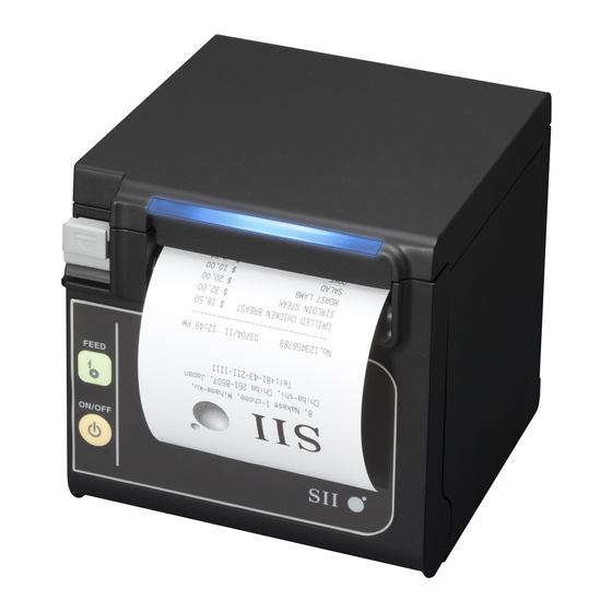
- Page 1 USER'S GUIDE Thermal Printer RP-E10 SERIES Read this user's guide carefully before using the printer. Keep this user's guide in a place where it can be accessed quickly.
- Page 2 This product is developed as a product for industrial equipment use. is a trademark of Seiko Instruments Inc. All other trademarks are the properties of their respective companies. Applicable EC Directive and Standards...
- Page 3 Federal Communications Commission (FCC) compliance statement This equipment has been tested and found to comply with the limits for a Class A digital device, pursuant to part 15 of the FCC Rules. These limits are designed to provide reasonable protection against harmful interference when the equipment is operated in a commercial environment.
-
Page 4: Table Of Contents
1. INTRODUCTION This manual describes how to handle RP-E10 thermal printer (hereinafter referred to as the printer), AC adapter, AC cable, and other accessories. Read through the "2. SAFETY PRECAUTIONS" and "3. OPERATING PRECAUTIONS" carefully before using the products, and handle them safely and properly. Keep this manual in a place where it can be accessed quickly. -
Page 5: Safety Precautions
2. SAFETY PRECAUTIONS In this SAFETY PRECATIONS, the following symbols are used to ensure safe and proper use of products and prevent from damaging devices. Failure to follow the instructions marked with this symbol could WARNING result in severe personal injury or death. Failure to follow the instructions marked with this symbol could CAUTION result in minor personal injury or property damage. - Page 6 OPERATING PRECAUTIONS WARNING Never attempt the followings. Failure to follow the instructions leads to fire, electric shock, or accident. Do not insert any foreign objects such as a piece of metal or any liquid into the products. Do not touch the metal parts of the terminal, AC plug, and DC plug. To avoid short circuits, prevent terminals of the products, AC plug, and DC plug from touching any conductor such as metal.
- Page 7 Procedures to take when in trouble Follow the instructions in the following cases. Failure to follow the instructions may lead to fire, electric shock, and accident. Turn off the printer and unplug the AC plug from an outlet in any of the following cases with the products: Abnormal status continues.
-
Page 8: Operating Precautions
3. OPERATING PRECAUTIONS Be careful of the following precautions and use the products properly in order to deliver and maintain the full performance of the products. Using the Products Be careful not to drop or bump the products on a hard surface. ◆... - Page 9 DO NOT use thermal papers taped together. ◆ NEVER pull out the thermal paper when the thermal paper is set. ◆ Make sure not to injure your body or other objects by the plate edge. ◆ Unplug the AC plug from an outlet when something goes wrong with the printer. ◆...
- Page 10 Notations The following 2 types of notations are used throughout this manual to denote operating precautions and items to remember besides the symbols shown in "2. SAFETY PRECAUTIONS": NOTE ◆ Operation Precautions This box contains items that may lead to a malfunction or to a deterioration of performance when not followed.
-
Page 11: Preparation
4. PREPARATION Make sure that the printer and its accessories are contained. Sample Thermal Paper Safety Precautions Printer (Top paper eject model) 58 mm Paper Width Partition Plate Quick Start Guide 58 mm Paper Width Spacer Plate Printer (Front paper eject model) - Page 12 Models including the AC adapter, AC cable, and interface cable are also available. Keep the package and packing materials for future transportation or long-term storage. The available accessories are shown below. See "18 SPECIFICATIONS" and "19 ACCESSORIES AND CONSUMABLE PARTS", and be sure to purchase our specified products listed on these references.
-
Page 13: Identifying The Model Type
5. IDENTIFYING THE MODEL TYPE The printer model is identified as follows: RP-E10-K3FJ1-U1C3 Direction of paper eject 0: From the top 1: From the front Case color W: White K: Black Interface S: Serial U: USB E: Ethernet 1: USB + Serial* Optional cable included Contact us for details. -
Page 14: Each Part Of Printer
6. EACH PART OF PRINTER Top paper eject model... - Page 15 Front paper eject model 15 17 USB model Serial model USB + Serial model Ethernet model...
- Page 16 1 POWER Switch 9 Paper-near-end sensor setting lever The POWER Switch turns on or off the printer. The lever sets the value to detect the remaining The LED lights when turning on the printer. To turn amount of the thermal paper. the off the printer, hold down the switch for longer than 3 seconds.
- Page 17 LED Display Printer Status LED (Color) (Lighting Pattern) Power off Power on (print-ready) Blue Printing Green Waiting for test print Green Blink-2 Paper-near-end Blue Blink-1 Output buffer full Green Blink-1 Out-of-paper error Yellow Blink-1 Cover open error Yellow Hardware error Head temperature error Violet Voltage error...
-
Page 18: Power Connection
7. POWER CONNECTION The printer can be powered with an AC adapter. Be sure to see "18. SPECIFICATIONS" for the AC adapter. The AC adapter and the AC cable are optional accessories. See "18 SPECIFICATIONS" and "19 ACCESSORIES AND CONSUMABLE PARTS", and be sure to purchase our specified products listed on these references. -
Page 19: Thermal Paper Setting
8. THERMAL PAPER SETTING The printer uses the thermal paper roll (hereinafter referred to as the thermal paper). The function settings of the printer differ depending on the used thermal paper. See "12 FUNCTION SETTINGS" for details. Thermal Paper Setting (1) Operate the release lever to the direction of the arrow shown in the figure below to open the paper cover. - Page 20 (4) Pull the thermal paper straight and then push the center of paper cover certainly to close it, to avoid one side lock defect. Top paper eject model Correct Incorrect Front paper eject model Correct Incorrect NOTE ◆ Pull the thermal paper straight. ◆...
- Page 21 Thermal Paper Shape Correct Incorrect Incorrect NOTE ◆ DO NOT use deformed thermal paper. Doing so may damage the printer. Correct Incorrect NOTE ◆ In case of using loosened thermal paper roll, rewind the roll before using it.
-
Page 22: Adjustment Of Remaining Thermal Paper
9. ADJUSTMENT OF REMAINING THERMAL PAPER The printer detects remaining amount of the thermal paper by the paper-near-end sensor. Detecting the paper-near-end requires the replacement of the thermal paper with new one. Removing Remaining Thermal Paper (1) Operate the release lever to open the paper cover. (2) Remove the thermal paper from the paper holder. - Page 23 [Top paper eject model] Paper-near-end Paper-near-end sensor setting lever sensor [Front paper eject model] Paper-near-end Paper-near-end sensor setting lever C sensor Paper-near-end Sensor Position Outside Diameter for Paper-near-end Detection φ22 ±2 mm in diameter (Top paper eject model) φ25 ±2 mm in diameter (Top paper eject model) φ22 ±2 mm in diameter (Front paper eject model) * φ25 ±2 mm in diameter (Front paper eject model)* *: Outside diameter for paper-near-end detection is not affected by the installed Wall Mounting Kit (WLK-B01-1).
-
Page 24: Prevention And Treatment Of Paper Jam
10. PREVENTION AND TREATMENT OF PAPER JAM Do not touch the thermal paper while the paper is being ejected or before it is cut. Covering the paper outlet or pulling out the paper during paper ejection may cause a paper jam, cut failure, or line feed failure. - Page 25 Cutter Error Treatment When the motor is locked during paper cutting due to a cutter error and the paper cover does not open, recover the printer according to the following procedure: (1) Turn off the printer. NOTE ◆ Be sure to turn off the printer before handling a cutter error. (2) Operate the release lever repeatedly to return the cutter blade to the home position.
-
Page 26: Test Print
11. TEST PRINT The printer can perform a test print. In the test print, the firmware version, setting value of function settings, etc. are printed. (1) Install thermal paper in the printer as instructed in " 8 THERMAL PAPER SETTING". Ensure that no error occurs, and then turn off the printer. -
Page 27: Function Settings
12. FUNCTION SETTINGS Various functions, such as the communication method after the power on and the type of thermal paper, can be preset to this printer. Set these functions before using the printer. The function settings of the printer are stored in the FLASH memory. They are effective until rewriting them again. -
Page 28: Connecting To The Host Device
13. CONNECTING TO THE HOST DEVICE There are 4 models in the printer: serial, USB, USB + Serial and Ethernet. The Function Settings of the printer differs depending on the communication method to be used. See "RP-E10 SERIES THERMAL PRINTER TECHNICAL REFERENCE" for details. An interface cable is required separately for the serial communication, USB communication or Ethernet communication. - Page 29 Ethernet interface cable NOTE ◆ When connecting an interface cable to the interface connector, push it until it clicks. ◆ NEVER connect plugs of other cables including drawer kick cable or phone line to the interface connector. ◆ When connecting an outdoor aerial-wired LAN cable, be sure to use it through another anti-serge device.
- Page 30 Connecting to the Drawer (1) Turn off the printer. (2) Connect the plug of drawer kick cable to the drawer kick connector on the back side of the printer. (3) Turn on the printer. NOTE ◆ When connecting or disconnecting the drawer kick cable, hold the plug and never pull the cable.
-
Page 31: Settings When Using 58Mm Paper Width
14. SETTINGS WHEN USING 58mm PAPER WIDTH (1) Turn off the printer. (2) Operate the release lever to open the paper cover. (3) Set the attached partition plate and the spacer plate to the position as shown in the figure below. See "RP-E10 SERIES THERMAL PRINTER TECHNICAL REFERENCE"... -
Page 32: Installation Of Accessories
15. INSTALLATION OF ACCESSORIES Wall Mounting Kit (WLK-B01-1) The Wall Mounting Kit is exclusive for the Front paper eject model. It cannot be used for the Top paper eject model. (1) Preparation Make sure that the product and its accessories are contained. Printer attachment screw (4 pieces) (Tapping screw 3×6) - Page 33 (2) Installation of Printer Bracket Firmly attach the printer bracket with 4 printer attachment screws as shown in the figure below. The tightening torque should be 39.2 cN•m (4 kgf•cm). NOTE ◆ Turn off the printer before the operation. ◆ Remove the AC cable of the AC adapter and the interface cable. (3) Installation of Wall Hanging Bracket Fix the wall hanging bracket to the mounting surface, and then secure it with 6 wall hanging bracket attachment screws.
- Page 34 (4) Installation of the Printer Slide the printer into the wall hanging bracket from the top to the bottom to insert the printer bracket into the wall hanging bracket, as shown in the figure below. NOTE ◆ Check the place and the material/structure of the wall, and then install the printer securely.
- Page 35 Back Plate (BCP-A01-K (Black), BCP-A01-W (White)) The Back Plate is exclusive for the Front paper eject model. It cannot be used for the Top paper eject model. (1) Preparation Make sure that the back plate and its accessories are contained. Back plate attachment screw Back plate (2 pieces)
- Page 36 (3) Installation of the back plate Put the projections which are located at the back of the back plate into the hole of the back side of the printer, and then firmly attach the back plate with 2 printer attachment screws as shown in the figure below.
-
Page 37: Printer Maintenance
16. PRINTER MAINTENANCE The thermal head of the printer does not require user maintenance. When paper powder accumulates, cleaning the thermal head can maintain the printing quality for an extended period of time. Cleaning Thermal Head/Platen/Rubber Feet (Front Paper Eject Model) (1) Turn off the printer. -
Page 38: Troubleshooting
17. TROUBLESHOOTING Check the following points before requesting for repair: The power does not turn on • Is specified AC adapter being used? • Are the AC cable and the AC adapter connected correctly? • Are the AC adapter and the printer connected correctly? ... -
Page 39: Specifications
18. SPECIFICATIONS Printer Specifications Item Specifications Model RP-E10, RP-E11 Printing method Thermal printing Number of characters per line Paper width 80 mm: 24 dots × 12 dots 48 digits (42 digits 16 dots × 8 dots 72 digits (64 digits Paper width 58 mm: 24 dots ×... - Page 40 AC Adapter Specifications (Specified accessories) Item Specifications Model PW-E2427-W1 Input voltage AC100 to 240 V, 50/60 Hz Rated output DC24.0 V, 2.71 A Dimensions (W × D × H) 53 mm × 114 mm × 37 mm* Mass Approx. 330 g Excluding the cable (Specified accessories) Item...
- Page 41 Sale Destinations Sale destinations of the printer and specified accessories are listed below. RP-E10 Country/Region AC Adapter AC Cable RP-E11 CB-JP07-20A Japan CB-JP08-20A EC (except UK), CB-CE04-20A EFTA PW-E2427-W1 CB-CE05-20A Turkey CB-UK03-20A CB-UK04-20A CB-US05-20A Canada CB-US06-20A PW-E2427-W2 Brazil...
-
Page 42: Accessories And Consumable Parts
19. ACCESSORIES AND CONSUMABLE PARTS Specified Accessories Name Model AC adapter PW-E2427-W1 PW-E2427-W2 AC cable* CB-JP07-20A, CB-JP08-20A CB-US05-20A, CB-US06-20A CB-CE04-20A, CB-CE05-20A CB-UK03-20A, CB-UK04-20A Wall mounting kit WLK-B01-1 Back plate (Black) BCP-A01-K Back plate (White) BCP-A01-W USB cable IFC-U02-2 Serial cable IFC-S02-2 Powered USB cable IFC-V01-1... - Page 43 Seiko Instruments Inc. 1-8, Nakase, Mihama-ku, Chiba-shi, Chiba 261-8507, Japan Print System Division Telephone:+81-43-211-1106 Facsimile:+81-43-211-8037 Seiko Instruments USA Inc. Thermal Printer Div. 21221 S. Western Avenue, Suite 250, Torrance, CA 90501, USA Telephone:+1-310-517-7778 Facsimile:+1-310-517-7779 Seiko Instruments GmbH Siemensstrasse 9, D-63263 Neu-lsenburg, Germany Telephone:+49-6102-297-0 Facsimile:+49-6102-297-222 info@seiko-instruments.de...
Need help?
Do you have a question about the SII RP-E10 Series and is the answer not in the manual?
Questions and answers