Table of Contents
Advertisement
Quick Links
Advertisement
Table of Contents

Related Manuals for Projecta INTELLI-RV PM200


Summary of Contents for Projecta INTELLI-RV PM200
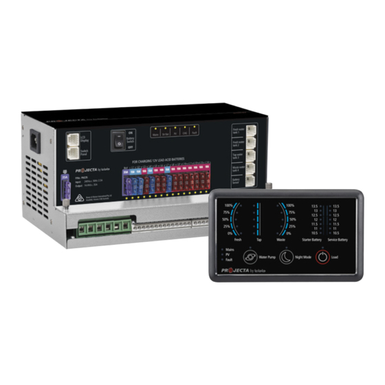
- Page 1 INTELLI-RV 12V POWER MANAGEMENT SYSTEM P/No. PM200...
- Page 2 IMPORTANT SAFETY INFORMATION Please read this manual thoroughly before use and store in a safe place for future reference. WARNINGS • Explosive gases. Prevent flames and sparks. Provide adequate ventilation during charging • Before charging, read the instructions • For indoor use. Do not expose to rain •...
-
Page 3: Table Of Contents
CONTENTS 1. SYSTEM INTRODUCTION – PM200 ................... 1.1 Features 1.2 LED display 1.3 Water tank probes 2. KEY FEATURES AND FUNCTIONS ....................2.1 Multiple inputs 2.2 Battery charger of stationery/service battery 2.3 Power supply mode 2.4 PWM solar charge controller 2.5 Voltage charging relay (VCR) 2.6 Categorised outputs 2.7 Battery low voltage protection... -
Page 4: System Introduction - Pm200
1. SYSTEM INTRODUCTION – PM200 PM200 is designed for use in caravans or motor homes. The unit has integrated functions such as: battery charger, distribution blocks, PWM solar charge controller, charging relay, battery low voltage protection, water pump controller, water tank indicator and LED Display. The PM200 is designed for an easy installation and a user-friendly interface. -
Page 5: Features
1.1 Features • Smart battery charger 12V 35A (30A for charging current) – Multi stage adaptive charging algorithm – Active Power Factor Correction (PFC) charging – Temperature compensation charging – Voltage compensation charging • Float charge for starter battery • Solar charge controller (PWM), 30A •... -
Page 6: Led Display
1.2 LED Display Figure 3 PMSWLED-2 switch panel Table 1 Front panel of PMSWLED-2 LABEL DEFINITION DESCRIPTION Water Pump DC load control Load control, on/off control Night Mode Scene mode Refer to 2.10 Load DC load control Load control, on/off control. Refer to 2.7 Fresh Water Tank Sensor Detect the level of fresh water tank... -
Page 7: Key Features And Functions
2. KEY FEATURES AND FUNCTIONS 2.1 Multiple Inputs AC MAINS PM200 master power unit may have multiple charging SOLAR sources at any one time. These sources include AC mains, STARTER solar and starter battery (vehicle). BATTERY Charging priorities are listed within the table to the right. CHARGING AC MAINS AC MAINS... -
Page 8: Categorised Outputs
2.5 PWM Solar Charge Controller PM200 has a built-in PWM charger for the service battery. • Max input voltage 30VDC • Max charging current 30A • Max supply current 30A 2.6 Voltage Charging Relay (VCR or commonly known as a VSR) PM200 Master Power Unit has a built-in voltage charging relay (VCR), which offers a convenient source to charge the service battery by alternator whilst the engine is running. -
Page 9: Structure And Installation
3. STRUCTURE AND INSTALLATION 3.1 PM200 Master Power Unit 10 11 12 13 14 15 16 17 19 20 22 2324 Figure 8 Front panel of PM235 LABEL DEFINITION DESCRIPTION AC Mains AC input port Ambient Temp Sensor Comm port Connect to switch panel LCD Display Comm port... -
Page 10: Led Display
128 55 Figure 9 Dimension of PM235 (Unit: mm) Installation: PM235 can be installed on a horizontal surface or vertically on a wall. Please see following instructions: Ensure clearance on both sides of PM235 unit upon installation. A recommended clearance of 5cm on each side. -
Page 11: Water Tank Probes
Installation: 28.1 HOLE SIZE 4-M3* 12mm Figure 12 Installation of PMSWELD (Unit:mm) 3.3 Water Tank Probe 3.3.1 PMWS400 Water Tank Probe Installation Figure 13 Dimension of PMWS400 (Unit:mm) Figure 14 Installation of PMWS400 3.3.2 PMWS200 Water Tank Probe Installation Figure 15 Dimension of PMWS200 (Unit:mm) Figure 16 Installation of PMWS200... -
Page 12: Wiring
4. WIRING 4.1 Material 4.2 System Schematic Figure 17 System diagram... -
Page 13: Preparation
4.3 Preparation PM200 system is designed with the concept of ‘Plug in and Play’ in mind. To complete the easy installation, a screw driver and DC cables are required. Follow Table 5 recommendation for minimum wiring size. CURRENT MINIMUM CABLE SIZE When running cables, if they pass through panels or wall, ensure the 0–5A 1.0mm... -
Page 14: Display
5. DISPLAY 5.1 PM235 Master Power Unit Figure 21 An overview of PM235 COLOUR STATUS DESCRIPTION AC input OK Mains GREEN AC disconnected Quick flashing (flash twice every second) AC input abnormal Starter battery charging the battery Slow flashing (flash once every second) The input of the Aux is normal but it is charged by the Starter Bat GREEN... -
Page 15: Led Display
5.2 LED Display Figure 22 An overview of PMSWLED-2 LABEL TYPE DESCRIPTION Water Pump DC Load Control Load control, on/off control Night Mode Scene Mode Refer to 2.10 Load DC Load Control Load control, on/off control. Refer to 2.7 Fresh Water Tank Sensor Detect the level of fresh water tank Tap Water Tank... -
Page 16: Operation
6. OPERATION 6.1 Configuration on PM200 Battery type and capacity are configured via PM235 master power unit. 6.1.1 Battery Capacity and Battery Type There is a dip switch for you to set battery capacity and battery type. 1 2 3 4 Dip switch definitions: SWITCH Charging Current... -
Page 17: Select Battery Switch Local/Remote
6.1.2 Select Battery Switch Local/Remote This function offers a possibility for user to use a remote battery switch to power on/off the service battery output Local DIP SWITCH DESCRIPTION Local The switch on PM235 unit works Remote The remote switch works and local one is disabled Remote Figure 24 Local/Remote Select Switch Table 16 Local/Remote Setting... -
Page 18: Trouble Shooting
7. TROUBLE SHOOTING 7.1 L.E.D Display on PM235 Unit COLOUR STATUS DESCRIPTION Mains GREEN Quick Flashing AC input abnormal (flash twice every second) Str Bat GREEN Quick Flashing The Starter Battery is 2~13.4V or >16.0V, while AC (flash twice every second) power is connected. -
Page 19: Specification
8. SPECIFICATIONS MODEL PM235 MODEL PM235 ELECTRICAL SPECIFICATIONS ELECTRICAL SPECIFICATIONS Grid Nominal input voltage 240±10%VAC Battery Disconnect voltage AGM/GEL/WET 10.5VDC 50/60Hz Disconnect (default) (LVD) Power factor 0.95 LFP (LiFePO 11.2 VDC (Default) Input current at full 2.5A load Delay off time 60 sec Battery Starter battery... - Page 20 WARRANTY STATEMENT Applicable only to product sold in Australia Brown & Watson International Pty Ltd of 1500 Ferntree Gully Road, Knoxfield, Vic.,telephone (03) 9730 6000, fax (03) 9730 6050, warrants that all products described in its current catalogue (save and except for all bulbs and lenses whether made of glass or some other substance) will under normal use and service be free of failures in material and workmanship for a period of two (2) years (unless this period has been extended as indicated elsewhere) from the date of the original purchase by the consumer as marked on the invoice.
Need help?
Do you have a question about the INTELLI-RV PM200 and is the answer not in the manual?
Questions and answers