
Related Manuals for Projecta SC420/ND


Summary of Contents for Projecta SC420/ND
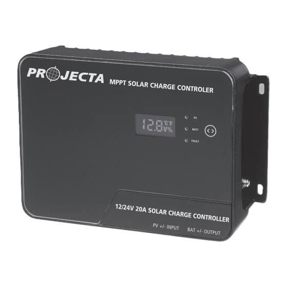
- Page 1 P/No. SC420/ND, SC440/ND MPPT Solar Charge Controller 4 STAGE CHARGING SC420/ND SC440/ND Pictured: SC420...
-
Page 2: Safety Tips
1. Safety Tips • Please ensure the instructions are read prior to any installation. • Keep instructions in a safe place for future reference. • SC420 and SC440 are designed for indoor use only • Beware of any nearby electrical equipment that may interfere with installing this device. Do not connect any AC sources to the controller as it may cause a fire/explosion and will permanently damage the device. -
Page 3: Product Features
2. Product Features • 4 Stage charging ensures the battery is charged to the optimum level • Advanced MPPT technology to improve charging efficiency in different weather and temperature conditions • Tempered glass cover with screen touch operation and sturdy aluminium housing • Selectable battery chemistry types, including AGM, GEL, WET and Lithium •... -
Page 4: Device Diagram
3. Device Diagram Description Description LCD Display Screen External Temperature Sensor Port LED Indicator (PV, BAT, FAULT) RS485 Communication Port Touch Screen Button Solar Input Terminals Installation Mounting Holes Battery Terminals Grounding Terminal Magnetic Cover... -
Page 5: Wiring Instructions
4. Wiring Instructions 1 & 2: Remove the magnetic cover, and put it aside 3. Unscrew the terminals completely, before inserting any wiring leads. 4. Insert the bare wire side of the cable to the 5. Check the wiring condition and put the terminal, and tighten the screws. -
Page 6: Operation
6. Operation 6.1 Voltage auto-recognition System startup: When the battery is connected, the system will automatically recognise the system voltage and briefly display this on the LCD display. 6.2 LCD Display Cycle Short press the touch screen button will cycle through the following four displays: - Battery Voltage - Battery SOC - Temperature - Error Code... - Page 7 6.4 LED Indication Chart LED Name LED Display Signal Indication Not In Charge Steady On In Charge Fast Flash Battery Over Voltage Steady On Battery On & Normal No Error or Alarm FAULT Steady On System with Error or Alarm...
-
Page 8: Parameters Setting
7. Parameters Setting 7.1 Selecting Battery Type To select the battery type, long press the touch button while the display is not showing the temperature. 08/22 This will enter the battery set mode. Short press while in this mode will cycle through the folowing chemistries: GEL (default) - For Gel type batteries L12 - For Lithium 12V batteries L24 - For Lithium 24V batteries... -
Page 9: Error Code Chart
8. Error Code Chart CODE Error Description Quick Troubleshoot No Error Battery output voltage has Battery Check whether there is an external voltage applied exceeded the controller’s max- Over-voltage to the battery imum rating Controller Controller has exceeded the Ensure the controller is placed Over-temperature ambient temperature limit in a well-ventilated area. -
Page 10: Controller Specification
9. Controller Specification Controller Specifications Parameter Model No. SC420/SC420-ND SC440/SC440-ND System Wiring Negative Grounded Grounded 12V/24V 12V/24V Battery System Auto (FLD/GEL/SEL/USER) Auto (FLD/GEL/SEL/USER) Voltage Manual (Li/User) Manual (Li/User) No-load Loss 12mA/12V; 10mA/24V 12mA/12V;10mA/24V Max Solar Input <100Voc <100Voc Voltage Rated Solar Charge Current Max Solar Input 300W/12V... -
Page 11: Controller Dimensions
10. Controller Dimensions SC420, SC420-ND Product Dimensions: 190*125*60mm Installation Area Dimensions: 180*80mm Installation Hole Size: 5*5mm Connection Socket Size: 7.5*7.5mm SC440, SC440-ND Product Dimensions: 218*150*65mm Installation Area Dimensions: 205*60mm Installation Hole Size: 5*5mm Connection Socket Size: 7.5*7.5mm... - Page 12 WARRANTY STATEMENT Brown & Watson International Pty Ltd (“BWI”) of 1500 Ferntree Gully Road, Knoxfield, Vic., telephone (03) 9730 6000, fax (03) 9730 6050, warrants that all products described in its current catalogue will under normal use and service be free of failures in material and workmanship for a period of three (3) years from the date of the original purchase by the customer as marked on the invoice. This warranty does not cover ordinary wear and tear, abuse, alteration of products or damage caused by the purchaser. To make a warranty claim the consumer must deliver the product at their cost to the original place of purchase or to any other place which may be nominated by either BWI or the retailer from where the product was bought in order that the warranty...
Need help?
Do you have a question about the SC420/ND and is the answer not in the manual?
Questions and answers