
Related Manuals for ThermoFisher Scientific iS20 with OMNIC


Summary of Contents for ThermoFisher Scientific iS20 with OMNIC
- Page 1 OMNIC Paradigm software FTIR Spectrometer USER GUIDE 269-3627 00 Revision A July 2023...
- Page 2 © 2023 Thermo Fisher Scientific Inc. All rights reserved. Microsoft, Windows and Excel are either trademarks or registered trademarks of Microsoft Corporation in the United States and/or other countries. All other trademarks are the property of Thermo Fisher Scientific Inc. and its subsidiaries. For technical support, please contact: www.thermofisher.com Thermo Fisher Scientific Inc.
-
Page 3: Table Of Contents
Table of contents Table of contents Table of contents Conventions used Contacting us Operation Turning the power on and off Indicators and buttons Installing a Smart Accessory Measuring data with the instrument Measuring data with the module Setting the purge gas controls Aligning your spectrometer Verifying the laser frequency Cooling a detector... - Page 4 Table of contents Changing the source Installing sidewall adapters Maintaining your instrument Cleaning your instrument Static electricity precautions Maintaining detector dewar Checking the humidity indicator Replacing the humidity indicator Replacing the desiccant Regenerating the desiccant Checking and changing the purge gas filter Troubleshooting Instrument problems Error messages...
-
Page 5: Conventions Used
Conventions used Conventions used Safety precautions and other important information use the following format: DANGER Avoid hazard. Indicates a hazardous situation which, if not avoided, will result in serious injury or death. WARNING Avoid hazard. Indicates a hazardous situation which, if not avoided, could result in serious injury or death. -
Page 6: Contacting Us
Contacting us Contacting us For Technical Support, please contact If you have problems with your system, refer to the Troubleshooting information for help, or call Technical Support. Ordering parts If you need to send the instrument or an accessory to us for repair, call or e-mail us first for any shipping requirements or other instructions. -
Page 7: Operation
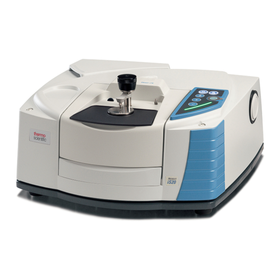
Operation Operation The Thermo Scientific™ Nicolet™ iS20™ spectrometer has integrated validation features, a powerful software suite, and many other features that make it easy for you to collect data. This document contains detailed information about performing such procedures. Turning the power on and off To turn the system power on or off, press the power switch on the power supply. -
Page 8: Indicators And Buttons
Operation Indicators and buttons The status indicators for the instrument are located on the touch panel, which is on the main cover of the instrument. The panel also has buttons that allow you to operate the instrument. Note With the release of OMNIC Paradigm software, functionality of the Background, Sample, Workflow, and Stop buttons has been streamlined into the OK/Enter button. -
Page 9: Installing A Smart Accessory
Operation Sample button. Measures the current sample installed in the instrument sample compartment. The sample data is ratioed with the background data, which leaves only the signals from the sample. (OMNIC software only.) Workflow button. Can be used to assign a software workflow (macro) to the touch panel for automated operations with the instrument. -
Page 10: Measuring Data With The Instrument
Operation Figure 1-1: Install transmission accessory Note If you want to remove a Smart Accessory, simply reverse the steps in this procedure. When you are not using an accessory, store it in a dust-free environment like a box or cabinet. For information about installing other kinds of accessories, see Installing other accessories Measuring data with the instrument... -
Page 11: Setting The Purge Gas Controls
Operation Setting the purge gas controls You must connect a source of purge gas (dry air or nitrogen) to purge your instrument of moisture and other environmental contaminants. For best results, the purge gas should be dried to a dew point of - 70 °C (-94 °F) or below. - Page 12 Operation 1. Open the shutoff valve. Figure 1-1: Open purge valve 2. Adjust the pressure regulator until the gauge indicates that the pressure is between 0.7 and 1.4 bar (70 to 140 kPa, or 10 to 20 psig). Thermo Scientific...
- Page 13 Operation Figure 1-2: Adjust purge pressure NOTICE Flow rates greater than 10 scfh can cause vibration that can affect data quality. We recommend keeping the flow rate at approximately 10 scfh. 3. Set the flowmeter to 10 scfh. Thermo Scientific...
-
Page 14: Aligning Your Spectrometer
Operation Figure 1-3: Set purge flowmeter Aligning your spectrometer Your instrument can be aligned automatically using OMNIC Paradigm software. Alignment optimizes the energy throughput to the detector. Alignment can change slightly over time, particularly in locations that have large temperature swings or excessive vibration. Note The instrument is aligned automatically each time you run a performance verification (PV) test. -
Page 15: Cooling A Detector
Operation Spectrometer Recommended Spectrometer state environment Schedule Stable Always powered on Every 3 months Unstable (e.g., Powered on and off Every day or once a temperature or humidity frequently week constantly changing) Note The laser is verified automatically each time you run a PV test. We recommend running a PV test at least once a month. - Page 16 Operation WARNING Avoid freeze burn hazard.Liquid nitrogen is extremely cold and potentially hazardous. Make sure you pour the liquid nitrogen slowly when you fill the vacuum bottle or the detector dewar. Pouring too quickly can cause liquid nitrogen to spray out. To prevent injury, always follow standard laboratory safety practices and wear protective clothing and eyewear when you use liquid nitrogen.
- Page 17 Operation Figure 1-2: Filling detector dewar 5. Remove the funnel. 6. Wait until the vapor plume disappears, and then replace the plastic stopper and close the dewar cover. 7. Wait 20 minutes, and then repeat the preceding steps to make sure the dewar is completely filled. Thermo Scientific...
-
Page 18: Installing Or Replacing Hardware
Installing or replacing hardware Installing or replacing hardware Installing a purge kit Purging your instrument protects the internal components from moisture and other environmental contaminants by maintaining an internal atmosphere of dry air or nitrogen. If your instrument is not already equipped to purge, you must install a purge kit. NOTICE We recommend that you maintain seal and desiccation and/or purge your instrument at all times. - Page 19 Installing or replacing hardware 1. Install a shutoff valve and either a 1/4 inch male fitting or a 3/8 inch female fitting on the purge gas source. (Choose a shutoff valve and fittings that are appropriate for the purge gas source.) Figure 1-1: Purge shutoff valve 2.
- Page 20 Installing or replacing hardware Figure 1-3: Connect pressure coupler 4. Install the purge filter, pressure regulator and flow meter, and snap the assembly into the pressure coupling. Figure 1-4: Connect purge 5. Connect the purge kit to your instrument, set the purge gas controls, and snap the flow coupler into the back of the instrument.
-
Page 21: Installing A Sample Compartment Extension Kit
Installing or replacing hardware Figure 1-5: iS20 purge connector Installing a sample compartment extension Time needed: 10 minutes or less Tools needed: 4-in-1 tool (included with your instrument) 5/32 inch hex wrench 1. Remove any Smart Accessory, then disconnect any cables that are connected at the back of the sample compartment. - Page 22 Installing or replacing hardware Figure 1-1: Sample compartment extension kit pins 3. Place the screws that came with the sample compartment extension kit into the holes in the sample compartment extension, and then use the 4-in1 tool with a Phillips bit installed to tighten the screws.
-
Page 23: Installing Baseplate-Mounted Accessories
Installing or replacing hardware Installing baseplate-mounted accessories To install the standard sample compartment baseplate (or an accessory mounted on that baseplate) make sure the sample compartment extension kit is installed, then orient the baseplate with the finger hole toward the front and lower the baseplate into the sample compartment. The baseplate fits over several alignment pins, which hold it in place. - Page 24 Installing or replacing hardware Figure 1-1: Standard sample holder Use the adjustment screw to position the sample vertically so that it is roughly centered in the infrared beam. Figure 1-2: Adjust sample height Thermo Scientific...
-
Page 25: Installing Other Accessories
Installing or replacing hardware Installing other accessories Note The following procedure explains how to install accessories that are not Smart accessories. This procedure applies only if a sample compartment extension kit has been installed. NOTICE Your accessory must be mounted on one of our baseplates. If it is not, you can remove an accessory from one of our baseplates and install your accessory on that baseplate. - Page 26 Installing or replacing hardware WARNING Avoid shock hazard. Do not attempt to remove the cover of the power supply. Before you replace the power supply, always make sure you have turned off your instrument and disconnected the power supply from the wall outlet or power strip.
- Page 27 Installing or replacing hardware 4. Turn on the instrument. The scan bar on the instrument touch panel cycles red, yellow, and green until the instrument is ready, then changes to a solid-pulsing green light. If your instrument does not function normally, turn off the power and check the cable connections between the power supply, the instrument, and the wall outlet or power strip.
-
Page 28: Changing The Source
Installing or replacing hardware Changing the source Both mid-IR and near-IR sources are available for your spectrometer. This procedure explains how to switch from one kind of source to the other. Time needed: 25 minutes or less Tools needed: 4-in-1 tool (included with your instrument) Finger cots, gloves, or laboratory tissue Alternate or duplicate source NOTICE... - Page 29 Installing or replacing hardware Figure 1-1: Loosen screws Note Do not twist the source as you remove it and do not touch the electrical contacts or the source element. Thermo Scientific...
- Page 30 Installing or replacing hardware 3. Remove the current source. Figure 1-2: Remove source 4. Insert the new source. Figure 1-3: Replace source Thermo Scientific...
-
Page 31: Installing Sidewall Adapters
Installing or replacing hardware 5. Use the 4-in-1 tool, with the small Phillips bit installed, to tighten the screws that hold the source in place. Do not overtighten the screws. 6. Turn on your instrument and start OMNIC Paradigm software. If you have installed a different type of source than you were previously using, choose Experiment Setup in the Collect menu, and then click the Bench tab in the Experiment Setup box. -
Page 32: Maintaining Your Instrument
Maintaining your instrument Maintaining your instrument Cleaning your instrument If the outside of your instrument needs cleaning, turn off the instrument and disconnect the power supply. When this is done, you can use a soft, damp (not wet) cloth and a mild soap to clean the outside of the instrument. -
Page 33: Maintaining Detector Dewar
Maintaining your instrument NOTICE Before you disconnect power supply, always discharge any static electricity that you may have accumulated by touching the metal base of your instrument. Do not touch any printed circuit board in the instrument, such as the circuit board on the detector. Do not remove replacement components from their protective packaging until you are ready to install that component in the instrument. -
Page 34: Checking The Humidity Indicator
Maintaining your instrument NOTICE If your instrument shows any of these symptoms, the detector dewar may have a vacuum leak. Contact us immediately for assistance. Leaving internal detector elements exposed to atmospheric pressure can permanently damage them. Note You can restore the vacuum in a detector dewar if you have the proper equipment. The vacuum must be pumped to approximately 5x10 torr. -
Page 35: Replacing The Humidity Indicator
Maintaining your instrument Replacing the humidity indicator The humidity indicator must be replaced when it turns white or does not return to blue after the desiccant has been replaced. Time needed: less than 1 minute Tools needed: Gloves, finger cots, or laboratory tissue Replacement humidity indicator NOTICE Use only Thermo Scientific certified replacement parts. - Page 36 Maintaining your instrument NOTICE Always wear lab gloves or finger cots, or use laboratory tissue, when handling the humidity indicator. Oil or moisture from skin can discolor the indicator. Note When installing the new humidity indicator, make sure the indicator is centered in the holder and that there are no gaps.
-
Page 37: Replacing The Desiccant
Maintaining your instrument Replacing the desiccant The optical components of your instrument are protected by two desiccant canisters that absorb moisture. As long as the humidity indicator on your instrument’s main cover is blue, the desiccant canisters are not saturated and do not need to be replaced. When the desiccant canisters become saturated, the humidity indicator turns pink or white. - Page 38 Maintaining your instrument Figure 1-1: Removing desiccant plate Figure 1-2: Removing desiccant cover. CAUTION Avoid hazard. The contents of the desiccant canisters can be harmful if ingested. If you discard the saturated desiccant canisters, make sure they are properly disposed of. Thermo Scientific...
-
Page 39: Regenerating The Desiccant
Maintaining your instrument 2. Lift the saturated desiccant canisters out of your instrument and install the new desiccant canisters. Figure 1-3: Lifting the desiccant cover 3. Use the 4-in-1 tool to install the desiccant cover, and then replace the 4-in-1 tool in its compartment and close the tool compartment door. -
Page 40: Checking And Changing The Purge Gas Filter
Maintaining your instrument Vented oven Insulated cloth or hot pad Note If you need to replace the humidity indicator, you must order new desiccant canisters. A new humidity indicator is included with the new desiccant canisters. NOTICE If you are going to dry and reuse saturated desiccant canisters, make sure you have fresh desiccant canisters that you can place in the instrument while the saturated canisters dry. - Page 41 Maintaining your instrument Figure 1-1: Changing the purge gas filter If the filter is green, it does not need to be replaced. If it is yellow or otherwise discolored, replace it according to the following procedure. NOTICE We recommend that you maintain seal and desiccation and/or purge your instrument at all times. Equipment damage due to failure to maintain seal and desiccation and/or purge is not covered under the warranty.
- Page 42 Maintaining your instrument 2. Remove the plastic bowl that houses the filter. You can unscrew the bowl by hand. Figure 1-3: Purge filter cover removal Thermo Scientific...
- Page 43 Maintaining your instrument 3. Remove the filter. You can unscrew the filter by hand. Figure 1-4: Purge filter cover removal 4. Install the new filter and replace the plastic bowl. 5. Turn on the purge flow to the instrument. Note You may notice increased levels of water and carbon dioxide in spectra collected immediately after you have had the purge gas turned off.
-
Page 44: Troubleshooting
Troubleshooting Troubleshooting The scan bar on the instrument touch panel reflects the current status of the System Status icon in OMNIC Paradigm software. Both locations provide important status information about the instrument. Using the Troubleshooting topics This section includes a variety of topics about troubleshooting and solving problems with your instrument. - Page 45 Troubleshooting If the System Status indicator has a green checkmark , the instrument is operating properly. If the System Status indicator is yellow , an instrument test has failed or is overdue. For more information, click the icon to open the System Status Overview box. Additional troubleshooting steps: 1.
- Page 46 Troubleshooting The system scans normally but the signal intensity is very 1. Align the instrument. See "Aligning your spectrometer". 2. In OMNIC Paradigm software, set the Optical Velocity setting to a lower velocity. 3. Check the Aperture setting. For an MCT detector, set Aperture to High Resolution. For a TEC DTGS detector, set Aperture to Medium Resolution.
- Page 47 Troubleshooting The alignment fails 1. Remove any sample or sampling accessory from the instrument sample compartment. 2. Check the humidity indicator on the instrument touch panel. If the indicator is pink, change the desiccant and the indicator. 3. Check all of the instrument indicators. 4.
-
Page 48: Error Messages
Troubleshooting Error messages The computer cannot communicate with the instrument 1. Close OMNIC Paradigm software, and then turn off the instrument power. Wait 90 seconds, and then turn on the instrument power. Allow the start-up sequence to finish and then restart OMNIC Paradigm software. - Page 49 Troubleshooting The MCT detector is warm 1. Cool the detector with liquid nitrogen. 2. Check the detector dewar for signs of leaks. If necessary, contact us to restore the dewar vacuum. 3. If the problem persists, contact us for assistance. The laser voltage is out of specification The ambient temperature of the room may be too high.
- Page 50 [This page intentionally left blank]...
Need help?
Do you have a question about the iS20 with OMNIC and is the answer not in the manual?
Questions and answers