Advertisement
Available languages
Available languages
Quick Links
H-9638, H-9639
H-10527, H-10528
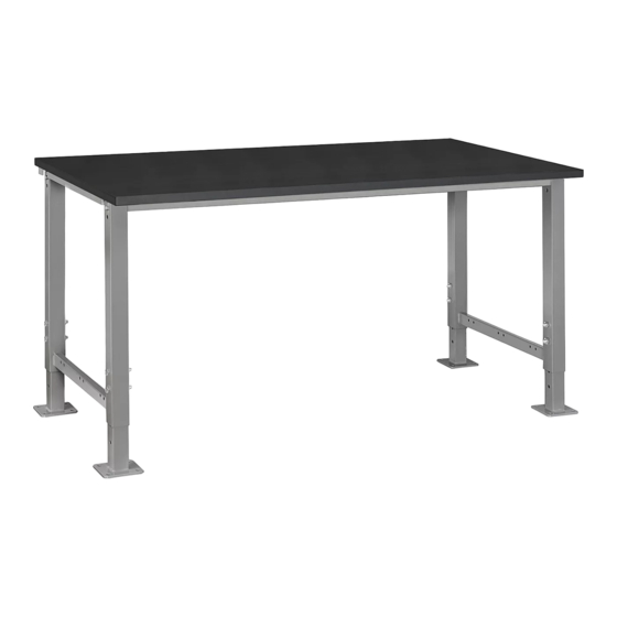
LAB WORKBENCH
TOOLS NEEDED
Drill
Flathead
Drill Bit
1
2
5
NOTE: Hardware packs are included in
tabletop and frame packaging. You may
receive more hardware than needed.
ONLY USE BLUNT-END SCREWS TO ATTACH TABLETOP TO FRAME
PAGE 1 OF 9
1-800-295-5510
uline.com
13 mm Wrench
Flathead
Screwdriver
17 mm Wrench
4
3
SHELF PARTS
6
CAUTION! Do not use pointed-end screws with steel frame packaging.
Pointed-end screws will protrude through tabletop if used.
PARTS
PARTS
#
DESCRIPTION
1
Leg
2
Adjustable Foot
3
Frame Support Bar
4
Phenolic Table Top
Tabletop
#28 1/4-20 x 1/2"
Blunt-end Wood Screw x 28
PARTS
#
DESCRIPTION
5
Full Depth Bottom Shelf
6
Bottom Shelf Support Bar
M8 x 40 Hex Bolt x 12
Para Español, vea páginas 4-6.
Pour le français, consulter les pages 7-9.
60 AND 72" QTY.
2
4
2
1
Hardware Kits
Steel Frame
M10 Nut x 8
M8 x 65 Hex Bolt x 8
M10 x 65 Hex Bolt x 8
60 AND 72" QTY.
1
2
Hardware Kit
M8 Nut x 4
1123 IH-9638
Advertisement

Related Manuals for U-Line H-9638


Summary of Contents for U-Line H-9638
- Page 1 Para Español, vea páginas 4-6. Pour le français, consulter les pages 7-9. H-9638, H-9639 1-800-295-5510 H-10527, H-10528 uline.com LAB WORKBENCH TOOLS NEEDED 13 mm Wrench Drill Flathead Flathead Screwdriver Drill Bit 17 mm Wrench PARTS PARTS DESCRIPTION 60 AND 72" QTY.
- Page 2 ASSEMBLY CAUTION! Some parts may have sharp edges. Care must be taken when handling various pieces to avoid injury. For your safety, wear a pair of work gloves when assembling. LEGS AND FRAME ASSEMBLY 3. While bottom shelf is sitting on leg braces, slide two bottom shelf support bars underneath shelf and align NOTE: Tabletop adds 1"...
- Page 3 ASSEMBLY CONTINUED TOP ASSEMBLY 1. To attach tabletop onto frame assembly, place tabletop on a smooth, non-marring surface with top side facing down. 2. Rotate assembled frame upside down and line up with pre-drilled holes in tabletop. Using #28 blunt- end wood screws and drill with flathead drill bit, attach frame to underside of tabletop.
-
Page 4: Herramientas Necesarias
H-9638, H-9639 800-295-5510 H-10527, H-10528 uline.mx MESA DE TRABAJO PARA LABORATORIOS HERRAMIENTAS NECESARIAS Desarmador Llave de 13 mm Taladro Broca Plana Plano Llave de 17 mm PARTES PARTES DESCRIPCIÓN CANT. PARA 60 Y 72" Pata Base Ajustable Barra de Soporte del Armazón Cubierta de Mesa Fenólica... - Page 5 ENSAMBLE ¡PRECAUCIÓN! Algunas partes pueden tener bordes filosos. Para evitar lesiones, debe tener cuidado cuando manipule varias piezas. Por su seguridad, utilice un par de guantes de trabajo cuando ensamble. ENSAMBLE DE LAS PATAS Y EL ARMAZÓN 3. Cuando la repisa inferior esté apoyada en los soportes para patas, deslice dos barras de soporte NOTA: La cubierta de mesa añade para repisa inferior por debajo de la repisa y alinéelos...
- Page 6 CONTINUACIÓN DE ENSAMBLE ENSAMBLE DE LA CUBIERTA Para asegurar la cubierta al ensamble del armazón, coloque la cubierta sobre una superficie plana que no deje marcas con el lado superior hacia abajo. 2. Gire el armazón ensamblado hacia abajo y alinee con los orificios preperforados en la cubierta.
-
Page 7: Outils Requis
H-9638, H-9639 1-800-295-5510 H-10527, H-10528 uline.ca ÉTABLI DE LABORATOIRE OUTILS REQUIS Tournevis à tête Clé de 13 mm Perceuse Mèche de perceuse à plate Clé de 17 mm tête plate PIÈCES PIÈCES QTÉ POUR 60 ET DESCRIPTION 72 PO Pied Patte réglable... -
Page 8: Montage
MONTAGE MISE EN GARDE! Certaines pièces peuvent avoir des bords tranchants. Manipulez les pièces avec soin pour éviter toute blessure. Pour votre sécurité, portez des gants de travail durant le montage. MONTAGE DES PIEDS ET DU CADRE 3. En gardant la tablette inférieure en travers des renforts de pieds, faites glisser deux barres de REMARQUE : La surface de table ajoute 1 po à... - Page 9 MONTAGE SUITE MONTAGE DE LA SURFACE Pour fixer la surface de table à l'ensemble du cadre, placez la surface sur une surface lisse et non marquante, face vers le bas. 2. Retournez l'ensemble du cadre à l'envers et alignez- le sur les trous prépercés de la surface de table. À l'aide de vis à...
Need help?
Do you have a question about the H-9638 and is the answer not in the manual?
Questions and answers