Advertisement
Available languages
Available languages
Quick Links
H-7562, H-7563, H-7564
π
H-9653, H-9654
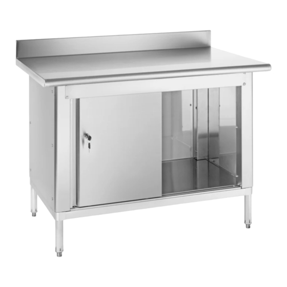
STAINLESS STEEL
CABINET WORKBENCH
TOOLS NEEDED
5/32" Allen
Phillips
Wrench
Screwdriver
(included)
Tabletop x 1
Undershelf x 1
Sliding Door x 2
Door Bracket x 1
PAGE 1 OF 18
1-800-295-5510
uline.com
Flat Head
Screwdriver
Back Panel x 1
Door Slide x 1
Rubber Mallet
PARTS
Leg x 4
Leg Cover x 4
Side Panel x 2
Para Español, vea páginas 7-12.
Pour le français, consulter les pages 13-18.
Set Screw
Set Screw x 13
Cover x 8
Large Phillips
Medium Phillips
Head Bolt x 41
Head Bolt x 3
Small Phillips
Head Bolt x 2
Lock Cover x 1
Caster x 4
(Optional)
1021 IH-7562
Lock x 1
Advertisement

Related Manuals for U-Line H-7562


Summary of Contents for U-Line H-7562
- Page 1 Para Español, vea páginas 7-12. Pour le français, consulter les pages 13-18. H-7562, H-7563, H-7564 π 1-800-295-5510 H-9653, H-9654 uline.com STAINLESS STEEL CABINET WORKBENCH TOOLS NEEDED 5/32" Allen Phillips Flat Head Rubber Mallet Wrench Screwdriver Screwdriver (included) PARTS Set Screw...
- Page 2 ASSEMBLY With the undershelf on its side, push the legs through the collars. (See Figure 1) 6" NOTE: In order for the tabletop to sit flush, the distance from the bottom of the leg tube to the 6" bottom of the shelf leg collar, must be 6". To ensure exact height, mark desired height on each leg with magic marker or grease pencil.
- Page 3 ASSEMBLY CONTINUED 4. Place door bracket onto side panels (at front of table) and secure using six large Phillips head bolts. Inside Outside View Two bolts should be used on the outside and one View bolt on the inside of each side of the door bracket. (See Figure 4) Door Bracket...
- Page 4 ASSEMBLY CONTINUED Place back panel onto shelf with lip facing down and out. Attach to side panels with six large Phillips head bolts. (See Figure 7) Back Panel Figure 7 8. Place door slide between side panels at front of cabinet and line up with pre-threaded holes. Attach to cabinet shelf with two medium Phillips head bolts.
- Page 5 ASSEMBLY CONTINUED 10. Use a flathead screwdriver to secure lock cover to door by folding cover tabs onto inside of door. (See Figure 10) Figure 10 11. From inside of door, align bolt holes and push lock through hole. Secure lock to door using a Phillips screwdriver and two small Phillips head bolts.
-
Page 6: Optional Casters
OPTIONAL CASTERS Flip the cabinet onto its back on a smooth, non-marring surface. Place flat head screwdriver in between leg and foot. Gently tap end of flat head screwdriver with a rubber mallet to remove adjustable feet from tube legs. (See Figure 13) Figure 13 2. -
Page 7: Herramientas Necesarias
H-7562, H-7563, H-7564 π 800-295-5510 H-9653, H-9654 uline.mx MESA DE TRABAJO DE ACERO INOXIDABLE CON GABINETE HERRAMIENTAS NECESARIAS Llave Allen de 5/32" Desarmador Desarmador Plano Mazo de (incluida) de Cruz Caucho PARTES 8 Cubiertas 13 Tornillos para Tornillos de Ajuste... - Page 8 ENSAMBLE 1. Con la repisa inferior de lado, empuje las patas por las ranuras. (Vea Diagrama 1) Pata 6" NOTA: Para que la cubierta de mesa quede al ras, la distancia de la parte inferior del tubo 6" de la pata a la parte inferior de la ranura para patas de la repisa debe ser de 6".
- Page 9 CONTINUACIÓN DEL ENSAMBLE 4. Coloque el soporte para puerta en los paneles laterales (al frente de la mesa) y asegúrelo usando Exterior Interior Vista Vista seis pernos grandes de cruz. Se deben utilizar dos pernos en el exterior y un perno en el interior en cada lado del soporte de la puerta.
- Page 10 CONTINUACIÓN DEL ENSAMBLE Coloque el panel posterior en la repisa con el reborde hacia abajo y afuera. Fije a los paneles laterales con seis pernos grandes de cruz. (Vea Diagrama 7) Panel Posterior Diagrama 7 8. Coloque el riel para puertas entre los paneles laterales al frente del gabinete y alinéelo con los orificios prerroscados.
- Page 11 CONTINUACIÓN DEL ENSAMBLE 10. Utilice un desarmador plano para fijar la cubierta para cerradura a la puerta doblando las pestañas de la cubierta hacia la parte interior de la puerta. (Vea Diagrama 10) Diagrama 10 11. Por dentro de la puerta, alinee los orificios de los pernos y empuje la cerradura a tráves de la abertura.
- Page 12 RUEDAS OPCIONALES 1. Voltee la mesa sobre una superficie lisa que no deje marcas. Coloque el desarmador de cabeza plana entre la pata y la base de la pata. Golpee suavemente el extremo del desarmador con un mazo de caucho para retirar la pata ajustable de los tubos de las patas.
- Page 13 H-7562, H-7563, H-7564 π 1-800-295-5510 H-9653, H-9654 uline.ca ÉTABLI À ARMOIRE EN ACIER INOXYDABLE OUTILS REQUIS Clé Allen de Tournevis Tournevis à tête Maillet en 5/32 po (inclus) cruciforme plate caoutchouc PIÈCES Cache-vis x 8 Vis de réglage x 13...
-
Page 14: Montage
MONTAGE 1. Avec la tablette inférieure posée sur le côté, poussez les pieds à travers les cols. (Voir Figure 1) Pied 6 po REMARQUE : Afin que la surface de table repose bien à plat, la distance entre le bas 6 po du tube de pied et le bas du col de pied de tablette doit être de 6 po. - Page 15 MONTAGE SUITE 4. Placez le support de porte sur les panneaux latéraux (à l'avant de la table) et fixez à l'aide de intérieure extérieure six grands boulons cruciformes. Deux boulons à l'extérieur et un boulon à l'intérieur sont à placer dans chaque côté...
- Page 16 MONTAGE SUITE Placez le panneau arrière sur la tablette en orientant le rebord vers l'extérieur et vers le bas. Fixez aux panneaux latéraux à l'aide de six grands boulons cruciformes. (Voir Figure 7) Panneau arrière Figure 7 8. Placez la coulisse de porte entre les panneaux latéraux à...
- Page 17 MONTAGE SUITE 10. Utilisez un tournevis à tête plate pour fixer le couvre-serrure à la porte en repliant les languettes de couve-serrure à l'intérieur de la porte. (Voir Figure 10) Figure 10 11. Alignez les trous de boulons de l'intérieur de la porte et poussez la serrure à...
- Page 18 ROULETTES OPTIONNELLES 1. Couchez l'armoire en arrière sur une surface plane et non marquante. Positionnez le tournevis à tête plate entre le pied et la patte. Tapotez l'extrémité du tournevis à tête plate avec un maillet en caoutchouc pour retirer les pattes réglables des tubes de pieds.
Need help?
Do you have a question about the H-7562 and is the answer not in the manual?
Questions and answers