Advertisement
Available languages
Available languages
Quick Links
H-2805
H-3109
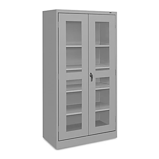
CLEAR-VIEW CABINET
PAGE 1 OF 12
1-800-295-5510
uline.com
Para Español, vea páginas 5-8.
Pour le français, consulter les pages 9-12.
TOOLS NEEDED
CAUTION! Some parts may have sharp
edges. Take care when handling various
pieces to avoid injury. For safety,
wear work gloves when assembling.
11/32" Nut Driver (included)
Flathead Screwdriver
Hammer
1120 IH-2805
Advertisement

Related Manuals for U-Line H-2805GR


Summary of Contents for U-Line H-2805GR
- Page 1 Para Español, vea páginas 5-8. Pour le français, consulter les pages 9-12. H-2805 H-3109 1-800-295-5510 uline.com CLEAR-VIEW CABINET TOOLS NEEDED 11/32" Nut Driver (included) Flathead Screwdriver Hammer CAUTION! Some parts may have sharp edges. Take care when handling various pieces to avoid injury. For safety, wear work gloves when assembling.
- Page 2 PARTS PRIMARY ASSEMBLY HANDLE ASSEMBLY DESCRIPTION QTY. DESCRIPTION QTY. Back Panel Locking Bar Set Left Side Locking Handle with Keys and Hardware Right Side Locking Cam Shelf Cotter Pin Sill Locking Bar Guide Insert (Nylon) Bottom Hinge Pin Nut Driver Left Door #8-32 x 3/8"...
- Page 3 ASSEMBLY INSTRUCTIONS Place the back (1) on a protected surface. 4. Attach the right side (3) to the back as done in step The bottom flange should be facing upward. 2. Make sure the flange is around the back and that (See Figure 1) the lances on the shelf adjustment strips are pointed in the same direction as those on the back and left...
- Page 4 ASSEMBLY INSTRUCTIONS CONTINUED Set the unit upright and tighten all nuts and bolts HANDLE/LOCKING SYSTEM INSTALLATION around the entire unit. 1. Place the locking handle (11) Figure 10 8. Insert the shelves (4) at on the right hand door and Figure 7 desired levels.
-
Page 5: Herramientas Necesarias
H-2805 800-295-5510 H-3109 uline.mx GABINETE CON FRENTE TRANSPARENTE HERRAMIENTAS NECESARIAS Llave de Tuercas de 11/32" (incluida) Desarmador de Cabeza Plana Martillo ¡PRECAUCIÓN! Algunas partes pueden tener bordes filosos. Tenga cuidado al manipular las distintas piezas para evitar lesiones. Para seguridad, use guantes de trabajo para ensamblar las partes. - Page 6 PARTES ENSAMBLE PRIMARIO ENSAMBLE DEL ASA DESCRIPCIÓN CANT. DESCRIPCIÓN CANT. Panel Posterior Juego de Barra de Seguridad Lado Izquierdo Asa de Bloqueo con Llaves y Accesorios Lado Derecho Leva con Seguro Repisa Pasador de Chaveta Umbral Inserta de la Guía de la Barra de Seguridad (Nylon) Parte Inferior Clavija de la Bisagra...
-
Page 7: Instrucciones De Ensamble
INSTRUCCIONES DE ENSAMBLE 1. Coloque el panel posterior (1) sobre una superficie 4. Fije el lado derecho (3) a la parte posterior como protegida. La pestaña inferior deberá mirar hacia hizo en el paso 2. Asegúrese de que la pestaña esté arriba. - Page 8 CONTINUACIÓN DE INSTRUCCIONES DE ENSAMBLE INSTALACIÓN DEL ASA/SISTEMA DE CIERRE Coloque la unidad en posición vertical y apriete todas las tuercas y los pernos de la unidad. 1. Coloque el asa de bloqueo Diagrama 10 8. Inserte las repisas (4) a (11) sobre la puerta derecha Diagrama 7 los niveles deseados.
-
Page 9: Outils Requis
H-2805 1-800-295-5510 H-3109 uline.ca CABINET À PORTES TRANSPARENTES OUTILS REQUIS Tournevis à douille de 11/32 po (compris) Tournevis à tête plate Marteau MISE EN GARDE! Certaines pièces peuvent avoir des bords tranchants. Faites attention lorsque vous manipulez les diverses pièces, afin d'éviter les blessures. - Page 10 PIÈCES ASSEMBLAGE PRIMAIRE ASSEMBLAGE DE LA POIGNÉE DESCRIPTION QTÉ DESCRIPTION QTÉ Panneau arrière Barre de verrouillage (ensemble) Panneau latéral gauche Poignée de verrouillage avec clés et quincaillerie Panneau latéral droit Came de verrouillage Tablette Goupille fendue Seuil de cadre Embout pour barre de verrouillage (nylon) Axe de charnière Haut Tournevis à...
-
Page 11: Instructions De Montage
INSTRUCTIONS DE MONTAGE Placez le panneau arrière (1) sur une surface 4. Fixez le panneau latéral droit (3) au panneau arrière protégée. La bride inférieure doit être orientée vers de la même manière qu'à l'étape 2. Assurez-vous que la bride repose du côté extérieur du panneau le haut. - Page 12 INSTRUCTIONS DE MONTAGE SUITE Placez l'unité en position verticale et serrez tous les INSTALLATION DE LA POIGNÉE DE VERROUILLAGE écrous et boulons de l'unité. 1. Placez la poignée de Figure 10 verrouillage (11) sur la porte 8. Insérez les tablettes (4) Figure 7 de droite et fixez à...
Need help?
Do you have a question about the H-2805GR and is the answer not in the manual?
Questions and answers