Table of Contents
Advertisement
Quick Links
Advertisement
Table of Contents

Related Manuals for GE AZ45E07DA Series


Summary of Contents for GE AZ45E07DA Series
- Page 1 GE Appliances Technical Service Guide April 2016 2016 Zoneline Air Conditioner 230/208 VOLT MODELS AZ45E07DA_ _1 AZ45E12DA_ _1 AZ65H07DA_ _1 AZ65H12DA_ _1 AZ45E09DA_ _1 AZ45E15DA_ _1 AZ65H09DA_ _1 AZ65H15DA_ _1 GE Appliances 31-9252 Louisville, Kentucky 40225...
- Page 2 GE Appliances Technical Service Guide Copyright © 2016 All rights reserved. This service guide may not be reproduced in whole or in part in any form without written permission from the GE Appliances. – 2 –...
-
Page 3: Table Of Contents
Table of Contents Safety Requirements ..................................6 Tools Required ....................................7 Introduction ....................................... 8 Nomenclature ....................................9 Operation ......................................10 Cooling ....................................... 10 Heating ...................................... 10 All Heat Pump Lockout Mode ............................13 Boost Heat Mode .................................. 13 Fan Cycle Operation ................................14 Fan Cycle - Resistance Heating Mode ........................ - Page 4 Service Main Board ................................30 User Interface ....................................32 Components ...................................... 33 Louvers ...................................... 33 Components ...................................... 35 Thermistors Indoor ................................35 Thermistors Outdoor ................................35 Indoor Fan Motor .................................. 36 Indoor Blower Wheel ................................36 Indoor Fan Bearing ................................37 Outdoor Fan Motor Shroud ..............................
- Page 5 Complete charging and recovery information for R410A is available in Service Guide 31-9192 ..55 Charging Summary ..................................56 Complete charging and recovery information for R410A is available in Service Guide 31-9192 ..56 Wiring Diagrams ....................................57 Early Production Wiring Diagram ............................57 Early Production Wiring Diagram ............................58 Serial range for Early Production Zonelines: VF101888 –...
-
Page 6: Safety Requirements
Safety Requirements GE Factory Service Employees are required to use safety glasses with side shields, safety gloves and steel toe shoes for all repairs. Electrically Rated Glove and Steel Toed Work Boot Dyneema®Cut Resistant Dyneema® Cut Resistant Glove Glove Keeper... -
Page 7: Tools Required
Additional Safety Requirements System Pressures Technicians with R-22 experience will need to become familiar working with high and low side pressures that are much higher when using R-410A. A typical R-22 system operates normally with a high side pressure of approximately 260 psi @ 120°F condensing temperature and a low side pressure of approximately76 psi @ 45°F evaporator saturation temperature. -
Page 8: Introduction
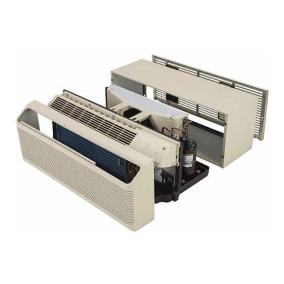
Introduction Zonelines are packaged room air conditioners that provide cooling and heating for residential and commercial properties. Available in 7,000, 9,000, 12,000 and 15,000 BTU models. Accessories are available to duct conditioned air into an adjoining room. The newly designed Zonelines are dimensionally the same size as older models and will t into existing wall cases. -
Page 9: Nomenclature
Nomenclature The nomenclature breaks down and explains what the letters and numbers mean in the model number. Serial Number The rst two characters of the serial number identify the month and year of manufacture. The letter designating the year repeats every 12 years. Example: LA123456S = June, 2013 2024 –... -
Page 10: Operation
Operation Cooling Heating AZ4500 In the cooling mode, the compressor, AZ4500 In the heating mode, AZ4500 will indoor fan and outdoor fan run. utilize the built-in resistance heater, running with the indoor fan at one of AZ6500 In the cooling mode, the compressor, two speeds determined by the Fan indoor fan and outdoor fan run, Speed selection. - Page 11 AZ6500 Automatic changeover between the compressor and the heating elements is utilized. When an AZ6500 Zoneline is in the heating mode, the resistance heater or the compressor runs with In order to keep the compressor from stalling out the appropriate fans. The control is capable of when trying to start against the high side refrigerant independently switching power for two resistance pressure, the control circuit has a built-in automatic...
- Page 12 • 3rd STAGE HEAT (HEATERS A AND B ONLY) When the room temperature falls below 2.7°F from the temperature control set point, the heat pump operation will stop. Stage 3 heating is activated (based on power cord) for all outdoor temperatures, except for l2R lock out conditions.
-
Page 13: All Heat Pump Lockout Mode
All Heat Pump Lockout Mode Boost Heat Mode AZ6500 series ONLY AZ6500 series ONLY The Heat Pump Lockout is controlled through the When the boost heat auxiliary set button is enabled auxiliary set mode. When this auxiliary set button and the outdoor temperature is above 25°F, the rst is On, the control will run in electric resistance heat stage heat (heat pump only) is locked out. -
Page 14: Fan Cycle Operation
Fan Cycle Operation There are two Fan Cycle auxiliary settings. These modes are utilized to switch between CONTINUOUS setting, the fan motor continues to operate even when the compressor or the electric heater cycles ON/OFF. In the CYCLE setting, the indoor fan cycles ON/OFF with the heating and cooling functions. When the Class 2 mode is selected, the fan motor is controlled by the remote wall thermostat, independent of positions of Fan Cycle auxiliary set button modes. -
Page 15: Fan Cycle - Resistance Heating Mode
Fan Cycle - Resistance Heating Mode The indoor fan and heaters are turned On at the same time. The indoor fan is turned O , approximately 20 seconds after the heaters are de-energized as shown. In the o mode, the indoor fan will continue to operate for six seconds after the user has stopped the Zoneline, in order to dissipate the heat inside the Zoneline. -
Page 16: Fan Cycle - Heat Pump Mode
Fan Cycle - Heat Pump Mode AZ6500 series ONLY The indoor fan is turned on 3 seconds before the compressor and outdoor fan is turned ON. The outdoor fan and the compressor are turned ON at the same time. The indoor fan is then turned OFF 6 seconds after the compressor and outdoor fan are turned OFF. -
Page 17: Constant Fan
Constant Fan In Constant Fan mode, the Zoneline operates in High fan mode regardless of fan setting. This feature allows the fan to operate even when the Zoneline is set in the OFF position. This will allow continuous air circulation in the room even if the Zoneline is turned o . -
Page 18: Random Restart
Random Restart The start-up condition for the di erent modes is shown in the following two gures. This function allows for the random restart of Zonelines in a building in the event of a power outage. The restart delay will reduce the initial inrush current from the building to help prevent a second power outage of inde nite length. - Page 19 Random Restart for AZ6500 Series Compressor Stop Compressor 3 mins. Power Down Power Recovered Range Cool Mode Stop Operation Operation Heat Mode Heat Pump Quick Heat Recovery Operation Range Power Down Power Recovered Stop Stop Stop Stop Mode Power Power Recovered Down The main board will power up the Zoneline randomly over a 3 to 20 seconds timing period.
-
Page 20: Freeze Prevention For Indoor Coil (Cooling)
Freeze Prevention for Indoor Coil (Cooling) Cooling Mode During the cooling operation, if the temperature of the indoor coil falls below 34°F for a period of approximately 5 minutes, the compressor will shut o . This will prevent the indoor coil from freezing. The compressor will start running again when the coil temperature reaches 50°F or above. -
Page 21: Indoor Coil Overheat Protection
Indoor Coil Overheat Protection Heat Pump Operation The Overheat Protection is only on the AZ6500 series. The OVERHEAT PROTECTION system protects the Zoneline from overworking when the outdoor temperature is too high for heat pump operation. The temperature of the indoor coil is monitored and if it rises above 131°F, the control stops the outdoor fan. -
Page 22: Reverse Cycle Defrosting Heat Pump Mode
Reverse Cycle Defrosting Heat Pump Mode Reverse Cycle Defrosting During Heat Pump Mode Reverse Cycle Defrost will be controlled as a function of compressor run time and outdoor coil temperature. Defrost Operating Sequence Defrost Enable When either of the conditions are detected, the The reverse cycle defrost will begin when either: Zoneline will initiate a reverse cycle defrost. -
Page 23: Internal Condensate Removal Control
Internal Condensate Removal Control Internal Condensate Removal Control (AZ6500 Only) The Internal Condensate Removal (ICR) function will be utilized to drip the condensation, from the base pan, onto the indoor coil to evaporate it when the compressor is running during the heat pump operation. During heat pump operation, the ICR system will pump condensate water from the Zoneline base-pan into a collector tray positioned above the indoor coil. -
Page 24: Heat Sentinel Mode
Heat Sentinel Mode Auxiliary Controls To prevent the room from overheating (Zoneline The RED auxiliary set button is located behind the must be powered), cooling is energized when the room cabinet, below the user interface. indoor temperature is sensed to be 85°F to maintain There are 10 di erent modes that can be set using room temperature below 85°F in any operation the auxiliary set button. -
Page 25: Aux Set
Aux Set Aux Set - Press the Red AU SET Button hen in the STOP Mode This menu allows the user to set up various con gurations. The display has a number 0 in the left digit, and the setting in the right digit. The heat and cool LED's are also used. On entry, the display shows AU. -
Page 26: Cdc - (Field Supplied)
CDC - (Field Supplied) Remote Thermostat The Central Desk Control (CDC) is a feature that The Remote Thermostat Connectors are included allows the Zoneline to be made operable/inoperable with each Zoneline. If required, order a replacement from a remote location. Operation of the feature (Part #: WP26X20983). -
Page 27: Controls
Controls Main Board - Front Cover MAIN BOARD The new Zoneline series uses a MAIN board that contains the microprocessor. It processes the information input from the USER interface or wall thermostat, the thermistors, and fan motors feedback. It then activates the associated relays for the selected cycle. -
Page 28: Main Board
Main Board J29 INDOOR THERMISTORS J30 OUTDOOR J2 INDOOR MOTORS J3 OUTDOOR HEATER PLUG J4 LOW VOLTAGE J21 COMPRESSOR TRANSFORMER DLB RELAY J23 ICR PUMP J22 REVERSING VALVE COIL AC INPUT PLUG – 28 –... -
Page 29: Component Checks At Main Board
Component Checks at Main Board Thermistors INDOOR J29 pin 1 - 2 AIR range 7k ohms to 64k ohms J29 pin 3 - 4 COIL range 10.5k ohms to 95k ohms OUTDOOR J30 pin 1 - 2 AIR range 3k ohms to 28.5k ohms J30 pin 4 - 5 COIL range 3k ohms to 28.5k ohms Indoor Fan Motor J2 pin 1 - 2 Blue to Yellow... -
Page 30: Service Main Board
Service Main Board Service Main Board (Continued next page) – 30 –... - Page 31 No model number is programmed into the service board so it must be con gured using the on-board DIP switches. S itch Position Meaning S2-1 o = heat pump on = air conditioner S2-2 BTU setting (See chart below) S2-3 BTU setting S2-4 Make-up air module tted...
-
Page 32: User Interface
User Interface The User Interface is a display board with tactile push button switches. There aren’t any processors contained on this board. There is a ferrite ring that the harness connecting the boards wraps around to minimize Electro-Magnetic Interference (EMI). Three screws secure the User Interface/Control Assembly to the chassis. -
Page 33: Components
Components Louvers The louver assembly is shipped from the factory with the air ow set to 45° from horizontal. To change the air ow to 85° from horizontal, remove the four screws and rotate the louver assembly and reinstall screws. Factory set with the air ow set to 45°... - Page 34 Thermistors Also, because R410a has much higher operating pressures, a pressure switch has been added to the Thermistors provide temperature feedback to the compressor discharge line and will remove power main board to maintain proper room temperature to the compressor if the sealed system pressure and operating conditions of the sealed system.
-
Page 35: Components
Components All Zoneline heat-pump models have two indoor Thermistors Indoor thermistors and two outdoor thermistors. Thermistors: All Zoneline models have two indoor One outdoor thermistor is attached to the outdoor thermistors which are attached to the indoor coil. coil and the other outdoor thermistor is set into the base assembly, enabling it to monitor outdoor air The indoor air thermistor is mounted on the front of temperature. -
Page 36: Indoor Fan Motor
Indoor Fan Motor The indoor fan motor turns a blower wheel which is attached to the motor shaft with a 4 mm Allen screw. The opposite end of the blower wheel inserts into a bearing assembly. The main board supplies high voltage DC to drive the fan motor and receives speed feedback from the motor. The motor is secured with a bracket and two screws. -
Page 37: Indoor Fan Bearing
Indoor Fan Bearing COMPONENTS – Indoor Fan Bearing Remove six screws to remove the end cap to access the bearing assembly. Two screws are used to secure the bracket attached to the indoor coil and end cap. Proper Bearing Placement NOTE: When reinstalling the bearing, ensure the shaft goes directly into the bearing assembly. -
Page 38: Outdoor Fan Motor Shroud
Outdoor Fan Motor Shroud The outdoor fan shroud provides proper air ow through the outdoor coil and also supports the outdoor fan motor. The outdoor fan shroud and motor assembly are attached to the base pan and outdoor coil assembly with twelve screws and a “sleeve”... -
Page 39: Outdoor Fan Motor
Outdoor Fan Motor The outdoor fan motor turns a slinger fan blade, which is attached to the motor shaft with a 3/8 in. regular thread nut. The motor is secured to the outdoor shroud with four 5/16 in. hex head shoulder bolts. NOTE: If the wire clip found below the motor breaks, secure the wire to the support with a wire tie. -
Page 40: Heater
Heater The heater assembly sets on the base pan and is secured by two screws on the left end cap. The thermal cut-outs are part of the heater assembly. They can be replaced separately if needed. NOTE: Some models have an additional inline Fuse fuse to the heater... -
Page 41: Power Cords
Po er Cords ICR System All new cords are required for both series of The Internal Condensate Removal system consists of Zonelines. They are redesigned to eliminate the AC a small pump that is driven by the main board. The jumper wires. -
Page 42: Damper Door
Damper Door Make-Up Air Module (MUAM) This feature allows outside air into the room. The This feature allows outside air to be “conditioned” door is secured with two screws from the factory before entering the room. that must be removed upon installation if the The module is secured with two screws and tabbed customer would like to use this feature. - Page 43 The Make-Up Air Module will turn on when the outdoor relative humidity is above 55%, and turns o when the relative humidity is below 50%. This is done by the outdoor humidistat located on the module. The module is designed to turn o the MUAM compressor when temperature is below 50°F.
-
Page 44: Sealed System
Sealed System Complete - cooling only - sealed system with all other components removed. Install a new drier in the liquid line tube between the outdoor coil and the capillaries. – 44 –... -
Page 45: Sealed System Heat Pump
Sealed System Heat Pump Sealed System Heat Pump Components 9,000 BTU heat-pump model shown. Reversing Valve On heat-pump models, the refrigerant ow direction is controlled by the reversing valve assembly. In the cooling mode, the main board supplies line voltage to the solenoid coil, which causes the valve to switch ow direction. -
Page 46: Service Replacement Vavle Assembly
Service Replacement Vavle Assembly Sealed System Common High Pressure S itch – on some models This electrical switch will shut down the compressor if too high of pressure is detected. It is part of the sealed system, tapped o of the compressor discharge line. -
Page 47: Electrical
Electrical Thermal fuse Capacitor Fuse link (230/208 models only) Low voltage transformer Fuse Link: The fuse link is in-line with the Capacitor: The capacitor assists the compressor compressor wiring and comes only as a complete starting and lowers the running current. harness assembly (ONLY on 230 volt models). -
Page 48: Low Voltage Transformer
Lo Voltage Transformer The low voltage transformer mounts to the control console with one screw and tab. One harness connector plugs into the main board. Screw The same transformer is used in all Zoneline models: 208/230 and 265 volt models. The 208/230 volt models use WHITE to RED for line input and BLACK to BLACK for 24 VAC output. -
Page 49: Condensate Removal
Condensate Removal If water that is collected o the indoor coil is not draining back to the base pan, clean the drain trough exit located on the left side of the trough. The water that is collected through the normal process of air conditioning is collected in the rear base pan. -
Page 50: Fault Codes
Fault Codes Fault Code Display Mode While the Zoneline is in the "OFF" mode, press and hold the FAN button with the AUX SET button simultaneously to enter into this mode. The Zoneline will then display all active fault codes held in memory, showing each one for 3 seconds on/o . - Page 51 Fault Code Fault Meaning E ect on operation hile fault Fault reset Number is ACTIVE time Compressor fault - No No e ect Fault clears temperature change has been after 3 detected after 1 minute of minutes. running. Reversing valve fault - No cooling or heat pump Fault clears Temperature change not...
-
Page 52: Service Mode
Service Mode Service Mode AZ6500 While the Zoneline is in "OFF" mode, press and hold 1. "CL": Cooling. Compressor, Indoor Fan, reversing the "+" and "-" buttons simultaneously with the AUX valve, and Outdoor fan are energized. Fan SET button to enter into this mode. speed is high. -
Page 53: Sealed System - Refrigerant Flow Cooling
Sealed System – Refrigerant Flo Cooling – 53 –... -
Page 54: Sealed System - Refrigerant Flow Heating
Sealed System – Refrigerant Flo Heating – 54 –... -
Page 55: Recovery Process
Recovery Process High Pressure Switch On Vapor Port Closed Filter Liquid Port Open High Side Tap Valve (WX5X328) 410A Recovery Cylinder Recovery Hose Hook-Ups Complete charging and recovery information for R410A is available in Service Guide 31-9192 – 55 –... -
Page 56: Charging Summary
Charging Summary Charging Summary Safety Switch Charging Hose Hook-Ups Complete charging and recovery information for R410A is available in Service Guide 31-9192 – 56 –... -
Page 57: Wiring Diagrams
Wiring Diagrams Early Production Wiring Diagram Some early production Zonelines utilized a thermal cut-out that looks like the image shown. This wiring diagram depicts how this cut out is wired into the circuit. NOTE: If this cut out opens, the compressor will only have the run winding energized and will shut o on the overload protector. -
Page 58: Early Production Wiring Diagram
Early Production Wiring Diagram – 58 –... -
Page 59: Latest Production Wiring Diagram
Latest Production Wiring Diagram Later production Zonelines utilize a thermal cut-out that looks like the image shown. This wiring diagram depicts how this cut out is wired into the circuit. NOTE: If this cut out opens, the compressor will be totally “inoperative”. Be sure to check this cut out before replacing the compressor. -
Page 60: Latest Production Wiring Diagram
Latest Production Wiring Diagram – 60 –... -
Page 61: Muam Wiring Diagram
MUAM Wiring Diagram The fans always run, when the power switch is ON, but the compressor cycles on/o during the following conditions: 1. The module is designed to turn the compressor system o when below 50°F. Dehumidi cation Range: Zoneline turns on at outdoor RH% above 55% and turns o below 50% RH, measured at the outdoor humidistat (located on the module). -
Page 62: New Accessories
Ne Accessories RA 204D15PA Sub-Base, 208/230-v, 15-A, w/ Power Cord RA 204D20PA Sub-Base, 208/230-v, 20-A, w/ Power Cord RA 204D30PA Sub-Base, 208/230-v, 30-A, w/ Power Cord RA 315P LCDI Power Cord, 208/230-v, 15-A RA 320P LCDI Power Cord, 208/230-v, 20-A RA 330P LCDI Power Cord, 208/230-v, 30-A RA 315SP... -
Page 63: Warranty
This warranty is extended to the original purchaser and any succeeding owner for products purchased for use within the USA and Canada. If the product is located in an area where service by a GE Authorized Servicer is not available, you may be responsible for a trip change or you may be required to bring the product to an Authorized GE Service location for service. -
Page 64: Index
Index auxiliary settings 14 Personality 27 Power Cord 62 Pressure Switch 29, 46 Proof 63 Capacitor 29, 47 CDC 17, 26, 62 Charging Summary 56 Check Valve 46 Recovery Process 55 Control Lock Out 24 Refrigerant Flow Cooling 53 Refrigerant Flow Heating 54 Remote Thermostat 26 REVERSING VALVE 28 drain pan plug 49...
Need help?
Do you have a question about the AZ45E07DA Series and is the answer not in the manual?
Questions and answers