
Related Manuals for VERDER VERDERAIR CONT-EX VA-C10


Summary of Contents for VERDER VERDERAIR CONT-EX VA-C10
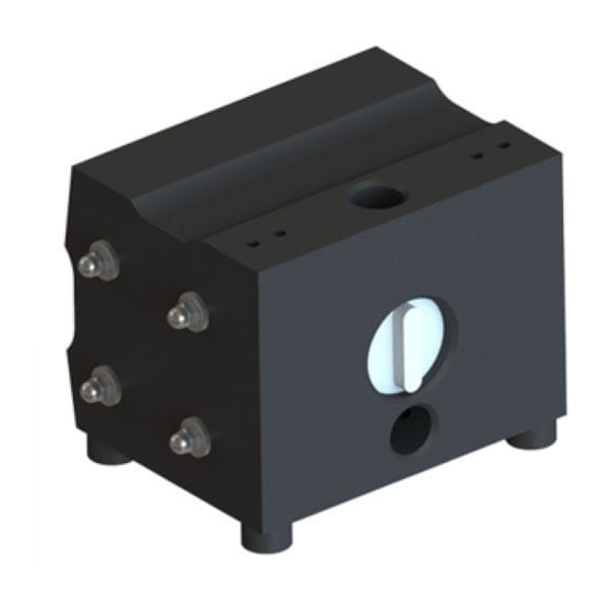
- Page 1 VERDERAIR CONT-EX Solid machined air operated diaphragm pumps Find you local supplier at www.verderair.com or scan the QR code...
-
Page 2: Table Of Contents
TABLE OF CONTENTS Pump Matrix Atex Warnings Installation Operation Maintenance / repair Trouble shooting Parts and kits Torque Values Exploded views Dimensions and mounting Performance charts Technical data Customer services & guarantee VA-C_man rev01-2016_VI_(uk) | 1.02.2017... -
Page 3: Pump Matrix
PumP mATRIX Before putting your pump in operation, NOTE: check the identification plate (ID) on the In case of doubt, please contact your pump. The ID is mentioning the year of local supplier. (www.verderair.com) To build a pump code, please use the construction, the serial number and the below coding system or use the pump construction code of the pump. -
Page 4: Atex
ATEX All pumps of the CONT-EX range are use, grounding, maintenance, and repair manufactured from Conductive Polyethylene of this equipment. The exclamation point and are ATEX certified II 2GD c T70°. symbol alerts you to a general warning The pumps have to be grounded following and the hazard symbol refers to procedure the instructions on page 8. -
Page 5: Warnings
WARNING EQuIPmENT mISuSE HAzARD Misuse can cause death or serious injury. Do not operate the unit when fatigued or under the influence of drugs or alcohol. Do not exceed the maximum working pressure or temperature rating of the lowest rated system component. See Technical Data in all equipment manuals. Use fluids and solvents that are compatible with equipment wetted parts. - Page 6 WARNING PLASTIC PARTS CLEANING SOLVENT HAzARD Use only compatible water-based solvents to clean plastic structural or pressure- containing parts. Many solvents can degrade plastic parts and cause them to fail, which could cause serious injury or property damage. See Technical Data in this and all other equipment instruction manuals.
-
Page 7: Installation
INSTALLATION PLEASE CHECk THE ADDITIONAL DELIVERED EXPLODED VIEW FOR ALL POSITION NumBERS Tighten Fasteners Before Setup Before using the pump for the first time, fluctuations, after transport, after check and retorque the housing bolts (23). dismantling of the pump and after periods Also the valve stops of the discharge valves when the pump hasn’t been working the stops, plugs and housing bolts have to be... - Page 8 mounting Air Line See recommended installation drawing on page 7. The pump exhaust air may contain 1. Install an air regulator and gauge. Set contaminants. Ventilate to a remote area. pressure of the driving air should be See Air Exhaust Ventilation on page 9. limited to the pressure required to run Never move or lift a pump under the pump on the desired working point.
- Page 9 Air Exhaust Ventilation Fluid inlet and outlet ports VA-C series of pump are having the suction and discharge connections integrated in the center block. Suction connection is horizontal Do not restrict the air exhaust port. and discharge vertical. Pay attention to this Excessive exhaust restriction can cause configuration as this is only valid for correct erratic pump operation.
-
Page 10: Operation
Starting and adjusting the pump 5. VA-C pumps are dry self-priming. So they 1. Be sure the pump is properly grounded. don’t need to be filled before first use. See page 8 for proper grounding. The figures of the possible suction heights 2. -
Page 11: Maintenance / Repair
Special precautions Preventive maintenance schedule 1. When medium is left in the pump Establish a preventive maintenance chambers, this can generate chemical schedule, based on the pump’s service reactions when pumping another fluid. history. This is especially important for Always flush pumps with a neutral fluid prevention of spills or leakage due to before changing from medium. - Page 12 Disassembly of the housing Disassembly of the valve seats and valve balls (or cylindrical valves). Unscrew the bolts on the assembly pins (23) on one side using a socket wrench. To have access to the valve seats and balls Remove the washers, than remove the side you need to disassemble the pump side housing (02-03).
- Page 13 Disassembly of the diaphragms and diaphragm shaft. Unscrew one diaphragm (17) (left turning) of the diaphragm shaft (19*). Figure 11 Assembly Before starting to assemble please check all Figure 9 parts on possible damages. Especially the Pull the diaphragm shaft (19*) with the sealing area of the diaphragms have to be second diaphragm out of the centre housing free from scratches (see Figure 12).
- Page 14 For VA-C50 and VA-C130 only : Adjust, when necessary, the position of the put the diaphragm shaft o-rings (20) in holes for the assembly pins by turning one the groove of the centre housing, by of the diaphragms a little backwards. forming them as kidney’s with locking ring pliers (see Figure 13).
- Page 15 Figure 16.1 Figure 16.5 Put the washers on the assembly pins and put the bolts on. Fasten the bolts crosswise up to the torque values as mentioned on page 22. Align both holes Figure 16.2 Figure 17 Always test the pump on leakages before using it.
-
Page 16: Trouble Shooting
Problem Cause Solution Pumps cycles at stall or falls to - Worn check valves and/or - Replace worn parts. hold pressure at stall. o-rings Pump will not cycle, or cycle - Air valve is dirty. - Clean or replace the air valve. once and stops. -
Page 17: Parts And Kits
PART & kITS Parts SEE SEPERATE PARTS LIST kits In case of break down, we recommend to have a spare part kit for your pump on stock. Spare part kits contains: Spare part kit, content Quantity O-ring side housing (22) Ball (11) / cylinder valve (10) Diaphragm (17) O-ring valve plug... -
Page 18: Exploded Views
EXPLODED VIEWS VA-C10 & VA-C20 POS. N° DESCRIPTION QuANTITy NEEDED CENTER HOUSING SIDE HOUSING RIGHT SIDE HOUSING LEFT SHOCK ABSORBER MUFFLER VALVE PLUG CYLINDER VALVE VALVE BALL (*) VALVE SEAT(**) O-RING SET VALVE PLUG DIAPHRAGM O-RING SET HOUSING ASSEMBLY PIN SET AIR VALVE VA-C_man rev01-2016_VI_(uk) | 1.02.2017... - Page 19 EXPLODED VIEWS VA-C50 & VA-C130 POS. N° DESCRIPTION QuANTITy NEEDED CENTER HOUSING SIDE HOUSING RIGHT SIDE HOUSING LEFT SHOCK ABSORBER MUFFLER VALVE PLUG CYLINDER VALVE VALVE BALL (*) VALVE SEAT(**) O-RING SET VALVE PLUG DIAPHRAGM DIAPHRAGM SHAFT SCREW SHAFT BEARING SET SHAFT O-RING SET HOUSING ASSEMBLY PIN SET AIR VALVE...
-
Page 20: Dimensions And Mounting
DImENSIONS M4 GROUNDING ALL TYPES H COMPRESSED AIR G DISCHARGE G SUCTION TyPE VA-C10 NPT 3/8" R 1/4" VA-C20 NPT 1/2" R 1/4" VA-C50 NPT 3/4" R 1/4" VA-C130 NPT 1-1/2" R 1/4" in mm TyPE VA-C10 3,54 3,70 5,20 NPT(f) 3/8"... -
Page 21: Performance Charts
PERFORmANCE CHARTS VA-C10 (102) (87) 0,25 Nm /min 5.45 SCFM (73) 0,1 Nm /min (58) 3.5 SCFM 0,05 Nm /min (44) 1.85 SCFM (29) (15) (0.44) (0.88) (1.32) (1.76) (2.20) (2.64) (3.08) (3.52) Liquid flow m /h (Gpm) VA-C20 (102) (87) 0,20 Nm /min... - Page 22 VA-C50 (102) 0,25 Nm /min (87) 0,15 Nm /min 8.8 SCFM 0,35 Nm /min 5.34 SCFM 12.4 SCFM (73) (58) (44) (29) (15) (2.20) (4.40) (6.60) (8.81) (11.05) (13.21) (15.41) (17.61) Liquid flow m /h (Gpm) VA-C130 (102) 0,2 Nm /min 0,4 Nm /min...
-
Page 23: Technical Data
TECHNICAL DATA ISO measurements Device model VA-C10 VA-C20 VA-C50 VA-C130 Nominal port size 3/8" 1/2" 3/4" 1 1/4" Air connection R 1/4" R 1/4" R 1/4" R 1/4" Weight Suction lift dry max with cylinder valves with ball valves Suction lift wet max Max particle size - suggested Max particle size - possible Max operating pressure... -
Page 24: Customer Services & Guarantee
CuSTOmER SERVICES & GuARANTEE Customer services Warranty disclaimer If you require spare parts, please contact Verder has made an effort to illustrate and your local distributor, providing the following describe the products accurately; however, details: such illustrations and descriptions are for...
Need help?
Do you have a question about the VERDERAIR CONT-EX VA-C10 and is the answer not in the manual?
Questions and answers