Table of Contents
Advertisement
Quick Links
Advertisement
Table of Contents

Related Manuals for ActronAir MGW-BACCS


Summary of Contents for ActronAir MGW-BACCS
-
Page 2: Table Of Contents
CONTENTS 1 Safety Precautions 1.1 Icon description 2 Product Description 2.1 Debugging for Use 2.2 BACnet 2.3 Web Functions 3 IP Address Resetting 4 Installation Instructions 4.1 Product Introduction 4.2 Product Dimensions 4.3 Installation Accessories 4.4 Installation Method... -
Page 3: Safety Precautions
1 Safety Precautions The Installation & Owner's Manual of this product describes how to properly handle the product, prevent personal injury and property losses, as well as how to use the product correctly and safely. Read the following carefully, make sure you understand the content (symbols and marks), and observe the precautions below. - Page 4 WARNING This unit must be installed by professional technicians. Users are not allowed to install the unit themselves; otherwise, personal injury or damage to the controller may occur. Other electrical wiring work must be carried out by a professional technician according to the circuit diagram.
-
Page 5: Product Description
2 Product Description MGW-BACCS Gateway (this Gateway) provides standard BACnet/IP services for VRF units. It is suitable for all ECOFLEX series units, that is, ECOFLEX ODUs and ECOFLEX IDUs. This Gateway supports 3 RS-485 buses and each bus is capable of connecting 8 ECOFLEX refriger- ant systems (the maximum IDU quantity is 64). -
Page 6: Debugging For Use
Indicator Item Status Description The Gateway is powered off. Power supply Steady on The Gateway is powered on. Off/Steady The Gateway main program has not started, or a serious error has occurred. Operating Blinking The Gateway main program is functioning normally. No abnormalities Fault Steady on... - Page 7 If the PC IP address is, for example, 192.168.1.100 and you enter "https://192.168.1.8" in the address bar of the Chrome browser, the following page will be displayed: Click to switch the language. Note: The language selection uses your browser's cache. When the browser is changed or the browser cache is cleared, the default language is restored.
- Page 8 2.1.1.1 Open the System Configuration page, and click "Edit" in the Ethernet pane, and edit relevant parameters in the opened dialog box. The IP Address, Subnet Mask and Gateway Address need to be provided by the IT Administration of the network it is connecting too. Note: After you change the IP address, this page will become unavailable, and you need to log in again by using the new IP address.
- Page 9 2.1.2 Check whether the BACnet function of the Gateway is normal on the VRF Bacnet Console page. Port 0 is X0Y0E, Port 1 is X1Y1E, and Port 2 is X2Y2E. As shown in the figure above, when you click an item in the left list, such as idu-19-2-0-0, the right pane will display the corresponding BACnet parameter values.
-
Page 10: Bacnet
2.2 BACnet 2.2.1 Bacnet Point Description 2.2.1.1 Bacnet Device The Gateway virtualizes VRF units as devices according to the specific type of the VRF units, and each device has different properties. Currently, conventional VRF IDU and ODU are involved. Each air conditioner connected to the Gateway has a unique BACnet device ID. Format of a BACnet device ID of a VRF unit: ABCDEFG Description BACnet configuration... - Page 11 Parameter Instance Parameter name Definition type Mode Operating mode AutoFan Auto fan speed or not Fan speed level FanGear Setpoint Set temperature CoolSetpoint Cooling temperature in auto mode Heating temperature in auto mode HeatSetpoint Room Temperature Indoor ambient temperature Malfunction Code IDU error code LRSwing Left/Right swing status...
- Page 12 Parameter Instance Parameter name Definition type SetLimitMaxCoolStp Setting of the upper limit of the cooling temperature Setting of the lower limit of the cooling temperature SetLimitMinCoolStp SetLimitMode Setting of the mode lock SetLimitOnOff Setting of the on/off lock SetLimitFan Setting of the fan speed lock SetLimitUDSwing Setting of the up/down swing lock SetLockRC...
- Page 13 ④ Inactive-text: No Error ⑤ Active-text: Error (3) Mode - Auto ① Object-identifier: BI 3 ② Object-name: AutoMode ③ Present-Value: current value of the variable, read-only, indicating auto mode or not Description Value Not auto mode Auto mode ④ Inactive-text:Not AutoMode ⑤...
- Page 14 Description Value Not auto fan speed Auto fan speed ④ Inactive-text: Not AutoFan ⑤ Active-text: AutoFan Note: Combine both AutoFan (BI 4) and FanGear (AI 2) to determine the current fan speed of the IDU. When AutoFan (BI 4) is 0, FanGear (AI 2) indicates the current fan speed of the IDU. When AutoFan (BI 4) is 1, the IDU is operating at auto fan speed, and FanGear (AI 2) indicates the actual fan speed level.
- Page 15 (8) Cooling Temperature in Auto Mode ① Object-identifier: AI 4 ② Object-name: Cool Setpoint ③ Present-Value: current value of the variable, read-only, indicating the set cooling temperature of the IDU in auto mode Note: In auto mode, two values are set for the IDU: CoolSetpoint (AI 4) and HeatSetpoint (AI 5). In other modes, Setpoint (AI 3) is set.
- Page 16 Meaning Value 0: No error 01-20: A0-AF, AH, AL, AP, AU 21-40: b0–bF, bH, bL, bP, bU 41-60: C0-CF, CH, CL, CP, CU 61-80: E0-EF, EH, EL, EP, EU 81-100: F0-FF, FH, FL, FP, FU 101-120: H0-HF, HH, HL, HP, HU Low byte of the error Error code table 121-140: L0-LF, LH, LL, LP, LU...
- Page 17 (12) Swing Left/Right ① Object-identifier: AI 8 ② Object-name: LRSwing ③ Present-Value: current value of the variable, read-only, indicating the current left/right swing status of the IDU (13) Swing Up/Down ① Object-identifier: AI 9 ② Object-name: UDSwing ③ Present-Value: current value of the variable, read-only, indicating the current up/down swing status of the IDU (14) Upper Limit of the Heating Temperature ①...
- Page 18 (15) Lower Limit of Heating Temperature ① Object-identifier: AI 11 ② Object-name: LimitMinHeatStp ③ Present-Value: current value of the variable, read-only, indicating the current lower limit of the heating temperature of the IDU The parameter range depends on the IDU. Lower Limit of Heating Temperature (16) Upper Limit of Cooling Temperature ①...
- Page 19 (19) On/Off Lock ① Object-identifier: AI 15 ② Object-name: LimitOnOff ③ Present-Value: current value of the variable, read-only, indicating the current on/off lock status of the IDU Unlocked On locked Off locked (20) Fan Speed Lock ① Object-identifier: AI 16 ②...
- Page 20 Unlocked Angle 1 locked Angle 2 locked Angle 3 locked Angle 4 locked Angle 5 locked Auto swing locked (22) Remote Controller Lock ① Object-identifier: BI 5 ② Object-name: LockRC ③ Present-Value: current value of the variable, read-only, indicating the current remote controller lock status of the IDU Description Value...
- Page 21 (25) T2A ① Object-identifier: AI 19 ② Object-name: T2A ③ Present-Value: current value of the variable, read-only, indicating the current T2A of the IDU (26) T2B ① Object-identifier: AI 20 ② Object-name: T2B ③ Present-Value: current value of the variable, read-only, indicating the current T2B of the IDU (27) IDU Model ①...
- Page 22 AHUKIT (return air control) Floor Standing AHUKIT (discharge air control) Note: Because new models are released regularly, some values may not be listed in the table. For the meaning of specific values, please contact the technical support. (28) IDU HP ①...
- Page 23 (2) Set Temperature ① Object-identifier: AO 2 ② Object-name: Setpoint Setting ③ Present-Value: current value of the variable, write-only, indicating the set temperature of the Note: In auto mode, two values are set for the IDU: Cool Setpoint Setting (AO 3) and Heat Setpoint Setting (AO 4).
- Page 24 (6) Setting Swing Left/Right ① Object-identifier: AO 6 ② Object-name: LRSwing Setting ③ Present-Value: current value of the variable, write-only, setting the left/right swing of the IDU Angle 1 Angle 2 Angle 3 Angle 4 Angle 5 Automatic (7) Setting Swing Up/Down ①...
- Page 25 (10) Setting of the Upper Limit of Cooling Temperature ① Object-identifier: AO 10 ② Object-name: SetLimitMaxCoolStp ③ Present-Value: current value of the variable, write-only, setting the upper limit of the cooling temperature of the IDU (11) Setting of the Lower Limit of the Cooling Temperature ①...
- Page 26 (14) Fan Speed Lock ① Object-identifier: AO 14 ② Object-name: SetLimitFan ③ Present-Value: current value of the variable, write-only, locking fan speed of the IDU Unlocked Fan speed 1 (low speed) locked Fan speed 2 (low speed) locked Fan speed 3 (medium speed) locked Fan speed 4 (medium speed) locked Fan speed 5 (high speed) locked Fan speed 6 (high speed) locked...
- Page 27 (17) Wired Controller Lock ① Object-identifier: BO 2 ② Object-name: SetLockWDC ③ Present-Value: current value of the variable, write-only, locking the wired controller of the IDU Unlock Lock 2.2.1.3 BACnet Device of VRF ODUs (1) Device Information Object Notes: ① Object-identifier: BACnet device ID of a VRF ODU ②...
- Page 28 Parameter Instance Parameter name Definition type Exhaust Temperature Discharge superheat Compressor 1 Current Compressor 1 current Compressor 2 Current Compressor 2 current EXV1 EXV1 EXV2 EXV2 EXV3 EXV3 EXV4 EXV4 SV8b SV8b Crank 1 Auxiliary electric heater 1 Crank 2 Auxiliary electric heater 2 Emergency Stop Emergency stop control...
- Page 29 ④ Inactive-text: Off ⑤ Active-text: On (2) Error Status ① Object-identifier: BI 2 ② Object-name: alarm indication ③ Present-Value: current value of the variable, read-only, indicating whether the IDU has an error No error Error ④ Inactive-text: No Error ⑤ Active-text: Error (3) Operating Mode ①...
- Page 30 (6) Fan 1 Status ① Object-identifier: BI 3 ② Object-name: Fan1 Status ③ Present-Value: current value of the variable, read-only, indicating fan 1 status of the ODU ④ Inactive-text: Off ⑤ Active-text: On (7) Fan 2 Status ① Object-identifier: BI 4 ②...
- Page 31 (11) Compressor 1 Status ① Object-identifier: BI 5 ② Object-name: Compressor 1 Status ③ Present-Value: current value of the variable, read-only, indicating compressor 1 status of the ④ Inactive-text: Off ⑤ Active-text: On (12) Compressor 2 Status ① Object-identifier: BI 6 ②...
- Page 32 (16) Low Pressure ① Object-identifier: AI 10 ② Object-name: Low Pressure ③ Present-Value: current value of the variable, read-only, indicating low pressure of the ODU (17) Error Code ① Object-identifier: AI 11 ② Object-name: Malfunction code ③ Present-Value: current value of the variable, read-only, indicating an error code of the ODU Meaning Value 0: No error...
- Page 33 0001 010110101 Note: The example here is for demonstration purposes only, and does not exist. Note: For error segmentations and system error or ID of the faulty component, refer to the corresponding manual of the ODU. (18) T3 ① Object-identifier: AI 12 ②...
- Page 34 (22) ODU HP ① Object-identifier: AI 16 ② Object-name: HP ③ Present-Value: current value of the variable, read-only, indicating the ODU HP (22) EXV1 ① Object-identifier: AI 17 ② Object-name: EXV1 ③ Present-Value: current value of the variable, read-only, indicating EXV 1 opening of the ODU (23) EXV2 ①...
- Page 35 (27) SV2 ① Object-identifier: BI 8 ② Object-name: SV2 ③ Present-Value: current value of the variable, read-only, indicating SV 2 status of the ODU ④ Inactive-text: Off ⑤ Active-text: On (28) SV3 ① Object-identifier: BI 9 ② Object-name: SV3 ③ Present-Value: current value of the variable, read-only, indicating SV 3 status of the ODU ④...
- Page 36 ④ Inactive-text: Off ⑤ Active-text: On (31) SV6 ① Object-identifier: BI 12 ② Object-name: SV6 ③ Present-Value: current value of the variable, read-only, indicating SV 6 status of the ODU ④ Inactive-text: Off ⑤ Active-text: On (32) SV7 ① Object-identifier: BI 13 ②...
- Page 37 (34) SV8b ① Object-identifier: BI 15 ② Object-name: SV8b ③ Present-Value: current value of the variable, read-only, indicating SV8b status of the ODU ④ Inactive-text: Off ⑤ Active-text: On (35) SV9 ① Object-identifier: BI 16 ② Object-name: SV9 ③ Present-Value: current value of the variable, read-only, indicating SV 9 status of the ODU ④...
- Page 38 ④ Inactive-text: Off ⑤ Active-text: On (38) ST3 ① Object-identifier: BI 19 ② Object-name: ST3 ③ Present-Value: current value of the variable, read-only, indicating ST 3 status of the ODU ④ Inactive-text: Off ⑤ Active-text: On (39) Electric Heater 1 ①...
- Page 39 ④ Inactive-text: Off ⑤ Active-text: On 2 Output Object(AO/BO) (1) Emergency Stop ① Object-identifier: BO 1 ② Object-name: Emergency Stop ③ Present-Value: current value of the variable, write-only, indicating the ODU emergency stop command ④ Inactive-text: Inactive Emergency Stop ⑤ Active-text: Active Emergency Stop This parameter will trigger the emergency stop logic of the ODU.
-
Page 40: Web Functions
2.3 Web Functions The Gateway is embedded with a web server, which can be used to upgrade and configure the Gateway. The default IP address of the Gateway is 192.168.1.8. In the address bar of the Chrome browser (*4), enter "https://Gateway IP address" to open the web page of the Gateway (*5). Username: admin Default password: 123AB@ab Note: The password is case-sensitive. - Page 41 Web function list Level-1 function Level-2 function Remarks module module System Time Changes the Gateway time. Ethernet Changes the Gateway IP address. Displays the Gateway version and upgrades the System Version Gateway firmware. System Load System Displays the usage of the Gateway CPU and memory. Configuration Configures the BACnet address and port, and Bacnet Configuration...
- Page 42 2.3.1 System Configuration 2.3.1.1 System Time Click "Edit" to open the system time setting dialog box, and click the time area to open the system time change window. Change the time and click "Submit". 2.3.1.2 Ethernet Click "Edit" to open the Ethernet setting dialog box. Enter the correct default gateway address, IP address, and subnet mask, and then click "Submit".
- Page 43 2.3.1.3 System Version Click "Edit" in the pane, click "Select the file", and select the desired firmware. (If a correct file is selected, the selected firmware version will be displayed.) Confirm the version and select upgrade and restart or upgrade without restarting. If the file is incorrect, verification will fail and the system will indicate an error.
- Page 44 Note: It takes 2-3 minutes to verify an upgrade file. While a file is being verified, do not refresh the page. Wait for the verification to complete. Upgrading firmware or restarting the gateway will not change the gateway's original settings. 2.3.1.4 System Load This pane displays the usage of the CPU, memory, and storage of the current device.
- Page 45 After the internal verification, be sure to disable Debug Mode. 2.3.1.6 Impedance Matching...
- Page 46 This pane displays the status of impedance matching. You can click "Edit" to enable or disable impedance matching for buses. 2.3.1.7 System Operation Click "reboot system" to soft reboot the gateway. 2.3.2 VRF Bacnet Console VRF BACnet debugging: You can use the BACnet protocol to obtain the list of names and positions of devices on the BACnet after the current gateway changes the protocol.
- Page 47 2.3.3 User User management: You can add, delete, and modify web users.
-
Page 48: Ip Address Resetting
3 IP Address Resetting If you forgot the IP address and cannot open the Gateway web page, do as follows to reset the IP address: Power off the Gateway, and short circuit the X0Y0E and X1Y1E ports (connect the X ends together, the Y ends together, and the E ends together, respectively). -
Page 49: Installation Instructions
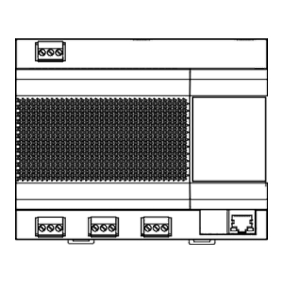
4 Installation Instructions 4.1 Product Introduction X0 Y0 E X1 Y1 E X2 Y2 E 4.2 Product Dimensions Unit: mm 51.5 74.5... -
Page 50: Installation Accessories
4.3 Installation Accessories Please check that you have all the following parts. Name Quantity Remarks Self-tapping screw ST4*20 Plastic expansion pipe For installing the controller onto the wall 3-pin black terminal For communication 3-pin gray terminal For connecting the power supply 4.4 Installation Method 4.4.1. - Page 51 Plastic expansion pipe Phillips head screw ST4*20 (This fixing screw is pre-inserted into the wall and the distance from the highest position of the nut to the wall is 5.5 mm) Drill with a 6mm drill bit, with a drill depth of no Phillips head screw ST4*20 less than 30mm...
Need help?
Do you have a question about the MGW-BACCS and is the answer not in the manual?
Questions and answers