
Related Manuals for Rockwell Automation Allen-Bradley Guardmaster MatGuard 440F-C28011


Summary of Contents for Rockwell Automation Allen-Bradley Guardmaster MatGuard 440F-C28011
- Page 1 MatGuard Mat Manager with MatGuard Pressure Sensitive Sensor Mats Catalog Numbers 440F-C28011, 440F-C28012, 440F-C28013, 440F-C28023, 440F-C28024, 440F-C28025, 440F-C28026 User Manual Original Instructions...
- Page 2 If this equipment is used in a manner not specified by the manufacturer, the protection provided by the equipment may be impaired. In no event will Rockwell Automation, Inc. be responsible or liable for indirect or consequential damages resulting from the use or application of this equipment.
-
Page 3: Table Of Contents
Wiring ............29 Rockwell Automation Publication 440F-UM001B-EN-P - January 2024... - Page 4 Spare Part List ..........68 Rockwell Automation Publication 440F-UM001B-EN-P - January 2024...
- Page 5 Index ............69 Rockwell Automation Publication 440F-UM001B-EN-P - January 2024...
- Page 6 Notes: Rockwell Automation Publication 440F-UM001B-EN-P - January 2024...
-
Page 7: Preface
IEC 62061: 2021 - Safety of machinery - Functional safety of safety-related electrical, electronic, and programmable electronic control systems. • ANSI B11.TR3 - 2000 (2015): Risk Assessment and Risk Reduction-A guide to estimate, evaluate, and reduce risks that are associated with machine tools. Rockwell Automation Publication 440F-UM001B-EN-P - January 2024... -
Page 8: Emc Directives
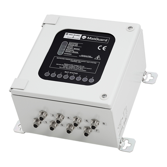
On some applications, to achieve an acceptable level of risk, it can be necessary to combine multiple types of safeguarding systems. Markings Figure 1 - Mat Manager Markings (440F-C2801xx) Rockwell Automation Publication 440F-UM001B-EN-P - January 2024... -
Page 9: Storage
Combinations of chemicals can have unpredictable effects. Tests are recommended in such cases. Small pieces of the vinyl material are available if tests are required. Rockwell Automation Publication 440F-UM001B-EN-P - January 2024... -
Page 10: Possible Misuse
The start or restart of the machine must only be possible by a separate and deliberate action at the designated machine controls. Rockwell Automation Publication 440F-UM001B-EN-P - January 2024... -
Page 11: Summary Of Changes
Industrial Automation Wiring and Grounding Guidelines, publication 1770-4.1 Provides general guidelines for installing a Rockwell Automation industrial system. Product Certifications website, rok.auto/certifications. Provides declarations of conformity, certificates, and other certification details. You can view or download publications at rok.auto/literature. - Page 12 Notes: Rockwell Automation Publication 440F-UM001B-EN-P - January 2024...
-
Page 13: Product Overview
Connections Uniting Trim Perimeter Trim MatGuard Mat Manager The mat manager provides connections for eight individual safety mats. The mat manager monitors the safety mats and deactivates outputs when a person is detected. Rockwell Automation Publication 440F-UM001B-EN-P - January 2024... -
Page 14: Pressure Sensitive Safety Mats
Your catalog selection defines the exit points on the safety mat wiring. When the safety mat is activated, the non-conductive compressible separators (shown as black) compress into their recess, which allows the two plates to make contact. Rockwell Automation Publication 440F-UM001B-EN-P - January 2024... -
Page 15: Matguard Mat Manager Functionality
See Table 2 on page 16 for connection types. IMPORTANT Safety mats must match the connection type of the controller unit. Rockwell Automation Publication 440F-UM001B-EN-P - January 2024... -
Page 16: Wiring The Mat Manager Safety Outputs
Figure 6 on page 17 is a typical illustration of the specific wiring required. See Mat Manager Installation and Wiring on page 35 for details on your specific unit. Rockwell Automation Publication 440F-UM001B-EN-P - January 2024... - Page 17 Any single electrical fault in the safety mat, wiring, or mat manager is detected and the mat manager outputs goes to a safe (off) state. Rockwell Automation Publication 440F-UM001B-EN-P - January 2024...
- Page 18 Chapter 1 Product Overview Notes: Rockwell Automation Publication 440F-UM001B-EN-P - January 2024...
-
Page 19: System Design
7). Other uses of the Guardmaster system, for example, solely as a perimeter access guard, or as a machine enabling device, are not recommended. Figure 7 - Layout Examples Hazard Hazard Safety Mats Rockwell Automation Publication 440F-UM001B-EN-P - January 2024... -
Page 20: Proper Positioning Of Safety Mats
(see Figure 9 on page 21). Applications that use the Guardmaster system as a combined trip and presence sensing Rockwell Automation Publication 440F-UM001B-EN-P - January 2024... - Page 21 Guardmaster safety mat detection zone to the nearest part of the hazard. The ISO 13855 formula for floor-mounted safety mats is: S = (1600 x T) + 1200 mm • S is the minimum safety distance in millimeters. Rockwell Automation Publication 440F-UM001B-EN-P - January 2024...
-
Page 22: Presence Sensing System Within A Guarded Perimeter
Requirements do not necessarily apply. In these applications, the Guardmaster system detects the presence of an operator to help prevent the perimeter-guarding system from being reset and the machine from being restarted while the operator is inside the enclosure. Rockwell Automation Publication 440F-UM001B-EN-P - January 2024... -
Page 23: Fixed Guards
Guardmaster safety mats must be minimized. This configuration typically requires additional angle plates and careful positioning of cable troughs. Good practice is illustrated in Figure 11 on page Rockwell Automation Publication 440F-UM001B-EN-P - January 2024... -
Page 24: Safety Mat Pattern
The vinyl outer surface of the safety mat is sealed to resist the ingress of liquids and rated to IP67. Safety mats resist bleaches, acids, salt, and most industrial chemicals. See Table 1 on page Rockwell Automation Publication 440F-UM001B-EN-P - January 2024... -
Page 25: Wear And Damage
If access to the mat manager is required for manual reset or routine indicator observation, it must be mounted at an accessible position outside the protection zone that provides a good view of the hazard and protection zone. Rockwell Automation Publication 440F-UM001B-EN-P - January 2024... -
Page 26: Electrical Interface
If personnel step on any of the safety mats, the safety outputs open and power to the loads is removed. After stepping off the safety mat, the Reset button must be pressed and released to re-energize the loads. Rockwell Automation Publication 440F-UM001B-EN-P - January 2024... -
Page 27: Reset Modes
Timing diagrams are given in Figure 15 Figure 16 on page 28 for both modes of the Guardmaster system. Rockwell Automation Publication 440F-UM001B-EN-P - January 2024... - Page 28 When used in the auto reset mode, the control system of the machine requires a separate reset function to help prevent machine startup when stepping off the safety mat, or after a temporary power supply failure or dip. Rockwell Automation Publication 440F-UM001B-EN-P - January 2024...
-
Page 29: Auxiliary Output
Final Details Prepare a work schedule and drawings of the system layout and the electrical circuit. We recommend that you record and retain all measurements and calculations in the technical file for the machine. Rockwell Automation Publication 440F-UM001B-EN-P - January 2024... - Page 30 Chapter 2 System Design Notes: Rockwell Automation Publication 440F-UM001B-EN-P - January 2024...
-
Page 31: Safety Mat Installation
32. Where the safety mat wires require extensions (for example, front safety mat to rear safety mat connections, and mat manager connections), use an extra pair of the butt connectors and a length of twin wire. Rockwell Automation Publication 440F-UM001B-EN-P - January 2024... - Page 32 Dimensions on page Active Uniting Trim Fixing on page 34, and Perimeter Trim Fixing on page 7. Install the mat manager and mounting, connect individual safety mats, and interconnect to the machine safety circuit. Rockwell Automation Publication 440F-UM001B-EN-P - January 2024...
-
Page 33: Safety Mat Dimensions
Add 10 mm (0.39 in.) for each uniting trim joint Nominal Mat Size + 6 mm (0.24 in.) Nominal Mat Size + 6 mm (0.24 in.) Active Safety Mat Uniting Trim 16 mm Detection Zone (0.63 in.) Floor Rockwell Automation Publication 440F-UM001B-EN-P - January 2024... -
Page 34: Active Uniting Trim Fixing
Notch the trim thoroughly so that the wiring is not trapped when the perimeter trim flexes. Verify that there are no sharp edges or burrs, which can damage the wires. Rockwell Automation Publication 440F-UM001B-EN-P - January 2024... -
Page 35: Mat Manager Installation And Wiring
Mount the mat manager in the planned position. All wiring to the mat manager includes: • Individual safety mat connections. • Power and I/O wiring (AC/DC voltage, inter-connection to wire safety outputs within the machine safety control circuit). Rockwell Automation Publication 440F-UM001B-EN-P - January 2024... -
Page 36: Mat Manager Enclosure Layout
Four M8 mounting bolts and hardware are required to mount the unit through the enclosure mounting tabs. See dimensions in Specifications on page (7.83) (9.45) 220 (8.66) 140 (5.51) 20.5 (0.71) (0.81) 165 (6.5) 260 (10.24) Rockwell Automation Publication 440F-UM001B-EN-P - January 2024... - Page 37 Reset mode) Individual safety mat connectors (pre-wired to Micro QD, except for 440F-C28024 and 440F-C28025) Internal error status indicator The ribbon cable ends at the main control board. Rockwell Automation Publication 440F-UM001B-EN-P - January 2024...
- Page 38 (all models except 1440F-C28013) All wiring to the mat manager routs through the connections on the enclosure. The configuration depends on the catalog number. See Table 3 on page Rockwell Automation Publication 440F-UM001B-EN-P - January 2024...
-
Page 39: Individual Safety Mat Connections
DIP switch selection. Open the cover to the mat manager and set the DIP switches as shown in Figure 31 on page Rockwell Automation Publication 440F-UM001B-EN-P - January 2024... -
Page 40: Safety Mat Selection
5. When complete, apply power to the system. Modified settings are now active. If there is a discrepancy, the system turns into the Internal Error status. See Internal Error on page 62 for details and how to fix the problem. Rockwell Automation Publication 440F-UM001B-EN-P - January 2024... -
Page 41: Safety Mat M12 Qd Connections
Figure 33 - M12 QD Connections Safety Mat Connector Mat Manager Connector S12 S21 S22 Checkered side brown white connected of safety mat brown white blue black black blue Rockwell Automation Publication 440F-UM001B-EN-P - January 2024... -
Page 42: Flying Lead Connections
However, depending on the detection zone that is designed with standard safety mats, it can be necessary to connect multiple safety mats together. See the connection diagram in Power and I/O Connector Diagrams on page Rockwell Automation Publication 440F-UM001B-EN-P - January 2024... -
Page 43: Power And I/O Connector Diagrams
2 (6.5) 889N-F12AC-2 2 Green 8 Violet 18 AWG 5 (16.4) 889N-F12AC-5 3 Yellow 9 Green/Yellow 22 AWG 4 Gray 10 Orange 300V 10 (32.8) 889N-F12AC-10 5 Rose 11 Blue 6 Red 2 Brown Rockwell Automation Publication 440F-UM001B-EN-P - January 2024... - Page 44 When any of the safety mats are stepped on, the safety outputs open and power is removed from the loads. • After you step off the safety mat, the Reset button must be pressed and released to reenergize the loads. Rockwell Automation Publication 440F-UM001B-EN-P - January 2024...
-
Page 45: C28023 Mat Manager
Convex crimp contacts 09330006104 Contact Harting for an appropriate mating assembly. 440F-C28023 Line (L1) 115/230 V AC Neutral (L2) Case Ground/E Safety Output #1 Safety Output #1 Safety Output #2 Safety Output #2 Rockwell Automation Publication 440F-UM001B-EN-P - January 2024... - Page 46 • Contactor K1 drops out and opens the latching circuit. • After you step off the safety mats, the Start button must be pressed to close the safety outputs and reenergize the loads. Rockwell Automation Publication 440F-UM001B-EN-P - January 2024...
- Page 47 When any of the safety mats are stepped on, the safety outputs open and power is removed from the loads. • After you step off the safety mat, the Reset button must be pressed and released to reenergize the loads. Rockwell Automation Publication 440F-UM001B-EN-P - January 2024...
-
Page 48: C28024 And 440F-C28025 Mat Managers
Table 7 - 440F-C28024 and 440F-C28025 Mat Managers Function Wire Color Controller Connection Gray Safety Output 1 White Pink Safety Output 2 Brown Power Blue Ground Green GND/E No connection Yellow No Connection Rockwell Automation Publication 440F-UM001B-EN-P - January 2024... - Page 49 The mat manager is configured for automatic reset. • Press and release the Start button to energize the loads. • When any of the safety mats are stepped on, the safety outputs open and power is removed from the loads. Rockwell Automation Publication 440F-UM001B-EN-P - January 2024...
-
Page 50: C28026 Mat Manager
Table 8 - 440F-C28026 Mat Manager Function Wire Color Controller Connection White Safety Output 1 Gray Red w/ Yellow Trace Safety Output 2 Pink Black Auxiliary Output Purple Monitoring circuit Yellow Blue Power Brown Ground Green GND/E Rockwell Automation Publication 440F-UM001B-EN-P - January 2024... - Page 51 Figure 46 - Connection Diagram for 440F-C28026 Mat Manager + 24V DC Fuse Reset Momentary Push Button 440F-C28011 Up to 8 Reset Mat Manager Safety Mat Auxiliary Output Motor DC Ground PE Ground Rockwell Automation Publication 440F-UM001B-EN-P - January 2024...
-
Page 52: C28013 Mat Manager
When any of the safety mats are stepped on, the safety outputs open and power is removed from the loads. • After you step off the safety mat, the Reset button must be pressed and released to reenergize the loads. Rockwell Automation Publication 440F-UM001B-EN-P - January 2024... -
Page 53: Reset Mode Selection
4. Check that the presence of a person between the hazardous zone and the safety mat is prevented. Rockwell Automation Publication 440F-UM001B-EN-P - January 2024... -
Page 54: Electrical Functions Check
2. Check the mat manager for the following: • Power status indicator is illuminated (green) • Auto Reset mode is illuminated (green) • Machine Enabled status indicator is illuminated (green) Rockwell Automation Publication 440F-UM001B-EN-P - January 2024... -
Page 55: Functional Checkout
Verify that the technical specifications, together with inspection, test, and service instructions, are available to the appropriate personnel and that an inspection record system is in place. Rockwell Automation Publication 440F-UM001B-EN-P - January 2024... - Page 56 Chapter 3 Install and Commission Notes: Rockwell Automation Publication 440F-UM001B-EN-P - January 2024...
-
Page 57: Safety Mat Cleaning
Start the machine, step onto the safety mat and check that the machine stops immediately. 5. Check that all fixed guards, angle plates, and so on, are in place, undamaged, and securely fixed. Rockwell Automation Publication 440F-UM001B-EN-P - January 2024... -
Page 58: Thorough Inspection And Test
We recommend twice yearly inspections or after damage. Test Contact your local Allen-Bradley distributor or Rockwell Automation sales office for information on an authorized testing service. A person who is competent in electrical and mechanical engineering must perform the tests. -
Page 59: Repair
User repairs are limited to replacement by new Guardmaster system parts. If problems occur, return the units to your local Allen-Bradley product distributor or Rockwell Automation sales office. Any repairs to the connecting wires must be made using the recommended butt splice connectors. - Page 60 Chapter 4 Maintenance Record of Thorough Inspection and Test on page 58 (every 6 months) Date: Inspected By: Comments: Rockwell Automation Publication 440F-UM001B-EN-P - January 2024...
-
Page 61: Status Indicators
Active when AC/DC power is applied to the mat manager Green Green: Run condition, nothing present on safety mat Mat Status 1….8 Red: Stop condition, safety mat actuated Green/Red/Off Off: Safety mat input is not used and is disabled via switches (off) Rockwell Automation Publication 440F-UM001B-EN-P - January 2024... -
Page 62: Internal Error
Check the primary and secondary fuses in the mat manager and replace if necessary. Verify that the correct value of fuse is used (500 mA anti-surge for both primary and secondary fuses). Rockwell Automation Publication 440F-UM001B-EN-P - January 2024... -
Page 63: No Stop
Record the replacement in the inspection log. If either fuse blows immediately or requires early replacement, contact your local Allen- Bradley distributor or Rockwell Automation sales office. 3. If the Machine Enabled status indicator on the Guardmaster mat manager is off and the Power status indicator is on, there is a fault in the system. - Page 64 Chapter 5 Status Indicators and Troubleshooting Notes: Rockwell Automation Publication 440F-UM001B-EN-P - January 2024...
-
Page 65: Matguard Mat Manager Specifications
Enclosure protection Steel, IP65 Torque settings - main 1.3 N•m screw Vibration 0.15 mm (0.01 in.), 10…55Hz Shock 10 g, 11 ms, half-sine Enclosure mounting Four M8 mounting hardware through the enclosure mounting tabs Rockwell Automation Publication 440F-UM001B-EN-P - January 2024... -
Page 66: Safety Mat Specifications
Operating temperature -10…+55 °C (-14…+131 °F) Storage temperature -40…+70 °C (-40…+158 °F) Storage Orientation Safety mats must be stored vertically Thickness 16 mm (0.63 in.) Size Add 6 mm (0.24 in.) to nominal size Rockwell Automation Publication 440F-UM001B-EN-P - January 2024... -
Page 67: Mat Manager Dimensions
4 x 42 (1.65) 4 x 30 (1.18) (7.83) (9.45) 220 (8.66) 140 (5.51) 20.5 (0.71) (0.81) 165 (6.5) 260 (10.24) (0.75) (0.75) (0.75) 4 x 14 (0.75) (0.75) 43.5 (0.75) (0.75) (1.71) Rockwell Automation Publication 440F-UM001B-EN-P - January 2024... -
Page 68: Spare Part List
External corner perimeter trim with cable channel 440F-T3014 Internal corner perimeter trim with cable channel 440F-T3015 Active uniting trim 440F-T3020 Vinyl wire guide 440F-T3230 440F-C4000P 440F-C4000S Safety mat controllers 440F-C4000D 440F-C28013 Fuse 500 mA 440R-A31562 Shorting plug 440F-A28639 Rockwell Automation Publication 440F-UM001B-EN-P - January 2024... - Page 69 65 internal 62 mats 14 measures against bypass 23 mechanical installation fixed guard 23 check 53 flying lead connection 42 functional checkout 55 nature of hazard 19 nature of safeguarding 19 Rockwell Automation Publication 440F-UM001B-EN-P - January 2024...
- Page 70 29 system design 19 presence sensing (guarded perimeter) 22 system components 13 system design requirement 23 test routine 57 thorough 58 thorough inspection and test 58 trim perimeter 14 uniting 14 troubleshoot 59 Rockwell Automation Publication 440F-UM001B-EN-P - January 2024...
- Page 71 MatGuard Mat Manager with MatGuard Pressure Sensitive Sensor Mats User Manual Rockwell Automation Publication 440F-UM001B-EN-P - January 2024...
- Page 72 At the end of life, this equipment should be collected separately from any unsorted municipal waste. Rockwell Automation maintains current product environmental information on its website at rok.auto/pec. Allen-Bradley, expanding human possibility, CompactBlock, Guard I/O, GuardLogix, Guardmaster, MatGuard, POINT Guard I/O, Rockwell Automation, and SmartGuard are trademarks of Rockwell Automation, Inc.
Need help?
Do you have a question about the Allen-Bradley Guardmaster MatGuard 440F-C28011 and is the answer not in the manual?
Questions and answers