Table of Contents
Advertisement
Installation Instructions
Original Instructions
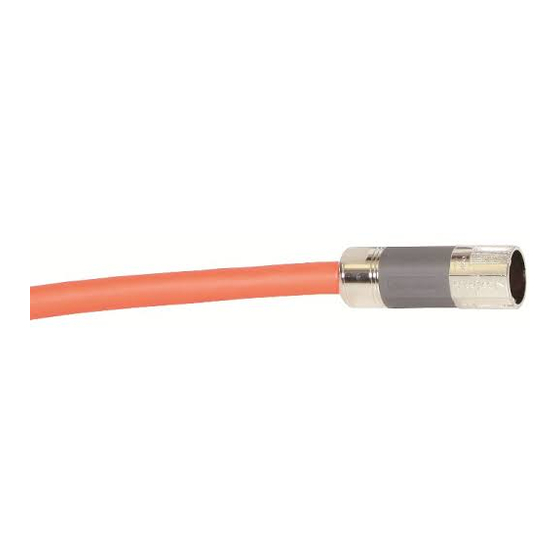
Build Your Own Kinetix TLP Motor Cables
Catalog Numbers 2090-KTPC-MA-AA, 2090-KTPC-MA-AE, 2090-KTFB-MA-AA, 2090-KTFB-MA-AE, 2090-
KTBK-MB-AA, 2090-KTBK-MB-AE, 2090-KTFB-MF-AA, 2090-KTFB-MF-AE, 2090-KTPC-MC-AA, 2090-KTPC-
MC-AE, 2090-KTPC-MD-AA, 2090-KTPC-MD-AE, 2090-KTPC-ME-AA, 2090-KTPC-ME-AE
Topic
Page
2
3
4
4
5
6
7
10
13
13
14
15
17
Advertisement
Table of Contents

Related Manuals for Rockwell Automation Allen-Bradley 2090-KTPC-MA-AA


Summary of Contents for Rockwell Automation Allen-Bradley 2090-KTPC-MA-AA
-
Page 1: Table Of Contents
Installation Instructions Original Instructions Build Your Own Kinetix TLP Motor Cables Catalog Numbers 2090-KTPC-MA-AA, 2090-KTPC-MA-AE, 2090-KTFB-MA-AA, 2090-KTFB-MA-AE, 2090- KTBK-MB-AA, 2090-KTBK-MB-AE, 2090-KTFB-MF-AA, 2090-KTFB-MF-AE, 2090-KTPC-MC-AA, 2090-KTPC- MC-AE, 2090-KTPC-MD-AA, 2090-KTPC-MD-AE, 2090-KTPC-ME-AA, 2090-KTPC-ME-AE Topic Page Before You Begin Wiring Configurations Rectangular Connectors Storage 6-pin Wire Selection and Preparation 9-pin Wire Selection and Preparation Crimping a Contact Contact and Connector Assembly... -
Page 2: Before You Begin
Conductor to Conductor Capacitance: 12AWG or smaller: 120 pF/m 08AWG: 150 pF/m 06AWG: 160 pF/m 04AWG: 190 pF/m Conductor to Shield Capacitance: 12AWG or smaller: 220 pF/m 08AWG: 270 pF/m 06AWG: 290 pF/m 04AWG: 320 pF/m Rockwell Automation Publication 2090-IN048A-EN-P - October 2019... -
Page 3: Wiring Configurations
H - BR- G - PE I - V MF-type Feedback Connector A - T+ B - T- C - BAT + D - BAT- L - Shield/Drain R - GND S - DC +5V Rockwell Automation Publication 2090-IN048A-EN-P - October 2019... -
Page 4: Rectangular Connectors
ATTENTION: Do not store product near any of these chemicals as they may cause stress corrosion cracking in the material: Alkalies, Ammonia, Citrates, Phosphates Citrates, Sulfur Compounds, Amines, Carbonates, Nitrites, Sulfur Nitrites, Tartrates. Rockwell Automation Publication 2090-IN048A-EN-P - October 2019... -
Page 5: 6-Pin Wire Selection And Preparation
Effective crimp length is defined as that portion of the wire barrel, excluding the bellmouth, fully formed by the crimping tool. Rockwell Automation Publication 2090-IN048A-EN-P - October 2019... -
Page 6: 9-Pin Wire Selection And Preparation
The front bellmouth must be visible. The end of the wire must be flush with the end of the wire barrel or protrude no more than the dimension shown in Figure 2. Do not move or bend the locking lances. Rockwell Automation Publication 2090-IN048A-EN-P - October 2019... -
Page 7: Crimping A Contact
Force applied during crimping can cause some bending between the crimped wire barrel and the mating portion of the contact. Such deformation is acceptable within the limits shown in Figure 3 (for 6-pin configurations) and Figure 4 (for 9-pin configurations). Rockwell Automation Publication 2090-IN048A-EN-P - October 2019... - Page 8 Strands Showing Crimping 0.10…0.51 [0.004…0.020] Wire Barrel Front Bellmouth Visible (Applicator) 0.10 [0.04] Min Contact Stop Not Crimped or Deformed Locking Lances Not Deformed 0.25 [0.010] Max Flash No Burrs on Cutoff Tab Rockwell Automation Publication 2090-IN048A-EN-P - October 2019...
- Page 9 Figure 3 - 6-pin Wire Straightness Restrictions 3° Max 3° Max Datum Line 3° Max 3° Max Figure 4 - 9-pin Wire Straightness Restrictions 4° Max Datum Line 4° Max 4° Max 10° Max 10° Max Datum Line Rockwell Automation Publication 2090-IN048A-EN-P - October 2019...
-
Page 10: Contact And Connector Assembly
1. Insert a crimped pin into the back of the plug until it clicks. 2. Slightly tug on the wire to confirm it is set correctly. 3. Repeat this process for the rest of the pins, and set aside. Rockwell Automation Publication 2090-IN048A-EN-P - October 2019... - Page 11 4. Insert a crimped socket into the back of the receptacle, until it clicks. 5. Slightly tug on the wire to confirm it is set correctly. 6. Repeat this process for the rest of the sockets. 7. Align and assemble the receptacle clamps around the receptacle. Rockwell Automation Publication 2090-IN048A-EN-P - October 2019...
- Page 12 9. Thread the screws through the clamp into the nut and hand tighten. 10. Repeat this process for the plug clamps. 11. Insert the receptacle into the plug all the way to verify that a proper connection is made. Rockwell Automation Publication 2090-IN048A-EN-P - October 2019...
-
Page 13: Military-Style Connectors
These products should be used on a first in, first out basis to avoid storage contamination. IMPORTANT Storage temperature for these components is -20…+70 °C (-4…+158 °F). Rockwell Automation Publication 2090-IN048A-EN-P - October 2019... -
Page 14: Wire Selection And Preparation
#16 (2) 1.25 1.95 2090-KTBK-MB-AE 2090-KTFB-MF-AA #16 (17) 1.25 1.95 2090-KTFB-MF-AE #12 (3) 2.95 2090-KTPC-MC-AA 2090-KTPC-MC-AE #16 (6) 1.25 1.95 #8 (3) 2090-KTPC-MD-AA 2090-KTPC-MD-AE #12 (6) 2.95 4.11 2090-KTPC-ME-AA #4 (4) 2090-KTPC-ME-AE 5.19 Rockwell Automation Publication 2090-IN048A-EN-P - October 2019... -
Page 15: Contact And Connector Assembly
3. Install heat shrink tubing (not included in kit) on each wire to be installed in the receptacle. 4. Insert the wires through the receptacle body, and then through the receptacle bushing. IMPORTANT 5. Rotate the wire contact and insert the wire as far as it goes. Rockwell Automation Publication 2090-IN048A-EN-P - October 2019... - Page 16 11. Insert the hardware to secure the receptacle bushing to the receptacle. 12. Screw the receptacle body to the receptacle bushing. 13. Secure the receptacle body with supplied hardware. 14. Repeat this process for the plug connection. Rockwell Automation Publication 2090-IN048A-EN-P - October 2019...
-
Page 17: Additional Resources
Information on how to install, configure, start, and troubleshoot your Manual, publication 2198-UM004 Kinetix 5100 servo drive system. Industrial Automation Wiring and Grounding Guidelines, Provides general guidelines for installing a Rockwell Automation industrial publication 1770-4.1 system. Product Certifications website rok.auto/certifications Provides declarations of conformity, certificates, and other certification details. - Page 18 Rockwell Automation maintains current product environmental information on its website at http://www.rockwellautomation.com/rockwellautomation/about-us/sustainability-ethics/product-environmental-compliance.page. Allen-Bradley, Kinetix, Rockwell Automation, and Rockwell Software are trademarks of Rockwell Automation, Inc. EtherNet/IP is a trademark of ODVA, Inc. Trademarks not belonging to Rockwell Automation are property of their respective companies.
Need help?
Do you have a question about the Allen-Bradley 2090-KTPC-MA-AA and is the answer not in the manual?
Questions and answers