Table of Contents
Advertisement
Quick Links
Installation Instructions
Original Instructions
MatGuard Pressure Sensitive Safety Mat System
Catalog Numbers 440F-C4000D, 440F-C4000P, 440F-C4000S, 440F-C28013
Topic
Summary of Changes
Introduction
Specifications
System Description
Applications
System Configuration
Safety Mat Positioning
Electric Interfacing
Final Safety Mat Layout
Wiring
Final Details
Installation
Commissioning
Maintenance
Repair
Replacement Parts
Service
Approximate Dimensions
Declaration of Conformity
Summary of Changes
This publication contains the following new or updated information. This list
includes substantive updates only and is not intended to reflect all changes.
Topic
Updated
Figure 1...Figure 4
Updated Conformity
Updated Safety mat conformity
Added Declaration of Conformity
Introduction
The MatGuard™ Pressure Sensitive Safety Mat System is designed for use as a
safety product in an industrial environment by professional personnel. The system
protects against risks that the isolation of electrical power when an operator is in
the vicinity of the hazard can minimize. This instruction covers the installation and
use of all parts of the system, including special shapes and sizes of safety mats.
Only suitably trained and qualified personnel must perform all installation
procedures in accordance with statutory requirements for safety. Read this
instruction in full before installation. After installation, retain this instruction in a
safe and accessible place. For further assistance, contact your local Allen-Bradley
product distributor or Rockwell Automation sales office.
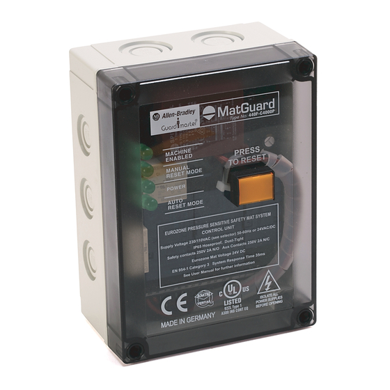
Figure 1 - Control Unit Marking 440F-C4000P and 440F-C4000S
Page
1
1
2
MACHINE
ENABLED
3
MANUAL
RESET MODE
5
POWER
AUTO
6
RESET MODE
7
MATGUARD PRESSURE SENSITIVE SAFETY MAT SYSTEM
CONTROL UNIT
9
Supply Voltage 230/110VAC (see selector) 50-60Hz or 24VAC/DC
IP65 Hoseproof, Dust tight
Safety Contacts 250V 2A N/O Aux Contacts 250V 2A N/C
MatGuard Mat Voltage 24VDC
12
EN ISO 13849-1 Category 3, System Response Time 35ms
See user manual for further information
12
ISOLATE ALL POWER
12
SUPPLIES BEFORE OPENING
13
18
18
Figure 2 - Control Unit Marking 440F-C4000D
19
•
+
A1
20
21
21
--
22
A2
Figure 3 - Safety Mat Marking
MatGuard
Page
MADE IN U.S.A.
1
REFER TO USER MANUAL
2
2
4 M 20 IND CONT EQ
22
EN 13856-1
Figure 4 - Mat Manager Markings 440F-C28013
MADE IN THE UK.
MACHINE
ENABLED
AUTO
RESET MODE
MANUAL
RESET MODE
POWER
MATGUARD PRESSURE SENSITIVE SAFETY MAT SYSTEM
Supply Voltage 230/110VAC (see selector) 50-60Hz or 24VAC/DC
IP65 Hoseproof, Dust tight
Safety Contacts 250V 2A N/O Aux Contacts 250V 2A N/C
MatGuard Mat Voltage 24VDC
EN ISO 13849-1 Category 3, System Response Time 35ms
See user manual for further information
1
2
3
PRESS TO RESET
(a)
The position of the Reset button differs on 440F-C4000 control units.
MatGuard
Type No:
440F-C4000P
PRESS
TO RESET
MADE IN THE UK
83HA TYPE 1 A300
IND CONT EQ
RESET IND
1
2
MC
Y1
Y3
MatGuard
440F-C4000D
EN 13856-1, EN ISO 13849-1 Cat 3
Response time: 35mS
MADE IN ENGLAND
RESET IND
3
4
MC
Y2
Y4
SENSOR MAT
Model No.
MatGuard
Type No:
440F-C28013
ISOLATE ALL POWER
SUPPLIES BEFORE OPENING
CONTROL UNIT
MAT STATUS
4
5
6
7
8
(a)
•
•
Y5
1 3
2 3
3 1
POWER
AUTO RESET MODE
Isolate
MANUAL RESET MODE
before
MACHINE ENABLED
opening
83HA A300
IND CONT EQ
•
•
Y6
1 4
2 4
3 2
Advertisement
Table of Contents

Subscribe to Our Youtube Channel
Related Manuals for Rockwell Automation Allen-Bradley Guardmaster 440F-C4000D


Summary of Contents for Rockwell Automation Allen-Bradley Guardmaster 440F-C4000D
- Page 1 See user manual for further information safe and accessible place. For further assistance, contact your local Allen-Bradley MAT STATUS product distributor or Rockwell Automation sales office. PRESS TO RESET The position of the Reset button differs on 440F-C4000 control units.
-
Page 2: Specifications
IP67 Mechanical life 1 x 10 operations Relative humidity 0…100% Safety mat outer cover material Vinyl Standard color Yellow Operating temperature range -10…+55 °C (14…131 °F) Storage temperature range -40…+70 °C (-40…+158 °F) Rockwell Automation Publication MATGRD-IN001C-EN-P - January 2024... -
Page 3: System Description
The system operates at 24V DC with restricted fault current. Therefore, damage to the safety mats or interconnecting wiring does not generate any electric shock hazard in normal circumstances. Rockwell Automation Publication MATGRD-IN001C-EN-P - January 2024... - Page 4 Manual Reset/ Auto Reset Control Unit N/O PB R IND 31 32 13 14 23 24 Volt Free Auxiliary Contacts for Indication necessary) L1 L2 L3 Sensor Remote Reset Push Button Mats (if necessary) Rockwell Automation Publication MATGRD-IN001C-EN-P - January 2024...
- Page 5 The system alone does not provide protection against hazards that arise from the ejection of materials, gases, and radiation. These applications can require additional protective measures, such as physical guards. • The system is not intended for use as a perimeter-only guard. Rockwell Automation Publication MATGRD-IN001C-EN-P - January 2024...
-
Page 6: System Configuration
Contact your local Allen-Bradley to ketones and most esters. distributor or Rockwell Automation sales office for further information, if necessary. IMPORTANT Combinations of chemicals can have unpredictable effects. - Page 7 Hazard Small and regular protrusions, such as a checker plate pattern, are acceptable. Skimmed concrete floors are ideal. If any doubt exists, contact your local Allen-Bradley distributor or Rockwell Automation sales office. Control Unit Mounting Approximate Dimensions on page 21. Do not mount the control unit within the Safety Mats detection zone.
- Page 8 Allow for conditions that can affect the response time, such as wear on brakes. Some circumstances can require an allowance for further delays in the machine control system. Rockwell Automation Publication MATGRD-IN001C-EN-P - January 2024...
- Page 9 Reset button operated (if in Manual Reset mode) • Machine start circuit enabled IMPORTANT If one or both of the contactors stick on, the motor stops when the safety mat is stood on and the fault is detected. Rockwell Automation Publication MATGRD-IN001C-EN-P - January 2024...
- Page 10 Contactor CONTACTOR Auxiliary AUXILIARY Control Unit Safety Mats Contacts SENSOR MATS CONTROL UNIT CONTACTS Motor MOTOR N/O PB R IND –VE 14 24 Protection PROTECTION (Thermal E.G. THERMAL Cutout) CUT OUT Fuse FUSES Rockwell Automation Publication MATGRD-IN001C-EN-P - January 2024...
- Page 11 If the value changes, repeat the safety distance calculations. conditions and under fault conditions. Figure 22 on page 12 Figure 23 on page 12 show both reset modes of the MatGuard safety mat system. Rockwell Automation Publication MATGRD-IN001C-EN-P - January 2024...
-
Page 12: Contactor Monitoring
PLC in systems that use PLC functional machine control in combination with hard wired safety circuits. Other uses include diagnostics in protection schemes, and/or driving status lamps or alarms. The safety function must not depend on this output. Rockwell Automation Publication MATGRD-IN001C-EN-P - January 2024... -
Page 13: Safety Mat Installation
Strip wires 8 mm (0.31 in.) and insert into the crimping barrel. Crimp using the correct cavity size on the crimp tool. Heat crimped splice using heat gun with deflector until tubing shrinks and adhesive shrinks and flows. Rockwell Automation Publication MATGRD-IN001C-EN-P - January 2024... - Page 14 Protect all wiring in suitable conduit. If possible, the wiring and conduit must not cross a floor area where it is a tripping hazard. If crossing the floor is unavoidable, enclose the wiring and conduit within the 440F-T3230 protective wire guide. Rockwell Automation Publication MATGRD-IN001C-EN-P - January 2024...
- Page 15 31 32 13 14 23 24 230v AUTO Date tick boxes 500 mAT Fuse Replacement Fuse replacement Up 110V Supply UP 110V SUPPLY Down 230V Supply DOWN 230V SUPPLY Automatic AUTOMATIC Manual MANUAL Rockwell Automation Publication MATGRD-IN001C-EN-P - January 2024...
- Page 16 Rockwell Automation Publication MATGRD-IN001C-EN-P - January 2024...
- Page 17 Press the Reset button: Machine-enabled status indicator illuminates. • When the safety mat operates: Machine-enabled status indicator turns off. • Stand off the safety mat: Machine-enabled status indicator is still off. • Press the Reset button: Machine-enabled status indicator illuminates. Rockwell Automation Publication MATGRD-IN001C-EN-P - January 2024...
-
Page 18: Functional Checkout
We recommend thorough inspections every 6 months or after damage. Maintenance Contact your local Allen-Bradley distributor or Rockwell Automation sales office for information on an authorized testing service. A person who is competent in During maintenance operations, disconnect the prime mover of the machine electrical and mechanical engineering must perform the tests. - Page 19 Record the replacement in the inspection log. If either fuse blows immediately or requires early replacement, contact your local Allen-Bradley distributor or Rockwell Automation sales office. If the machine-enabled status indicator on the safety mat control unit is off and the power status indicator is on, there is a fault in the system. On...
-
Page 20: Replacement Parts
440F-T2015 1000 x 1000 39.4 x 39.4 440F-M2020BYNN 440F-T2020 1000 x 1200 39.4 x 47.2 440F-M2024BYNN 440F-T2024 1000 x 1250 39.4 x 49.2 440F-M2025BYNN 440F-T2025 1000 x 1500 39.4 x 59.1 440F-M2030BYNN 440F-T2030 Rockwell Automation Publication MATGRD-IN001C-EN-P - January 2024... -
Page 21: Approximate Dimensions
Figure 35 - 440F-C4000S Control Unit and 440F-C28013 Mat Manager (Steel) [mm (in.)] (6.5) (9.1) 11 (0.43) Record of Thorough Examination and Test on page 18 (every 6 months) 210 (8.3) 143 (5.6) Date Inspected By Comments 225 (8.9) 4 x M6 (0.23) Rockwell Automation Publication MATGRD-IN001C-EN-P - January 2024... -
Page 22: Declaration Of Conformity
MatGuard Pressure Sensitive Safety Mat System Installation Instructions Declaration of Conformity CE Conformity Rockwell Automation declares that the products that are shown in this document conform with the essential requirements of the 2014/30/EU EMC Directive and 2006/42/EC Machinery Directive. For a comprehensive CE certificate visit: rok.auto/certifications. - Page 23 MatGuard Pressure Sensitive Safety Mat System Installation Instructions Notes: Rockwell Automation Publication MATGRD-IN001C-EN-P - January 2024...
-
Page 24: Rockwell Automation Support
Rockwell Otomasyon Ticaret A.Ş. Kar Plaza İş Merkezi E Blok Kat:6 34752 İçerenköy, İstanbul, Tel: +90 (216) 5698400 EEE Yönetmeliğine Uygundur Allen-Bradley, expanding human possibility, GuardMaster, MatGuard, and Rockwell Automation are trademarks of Rockwell Automation, Inc. Trademarks not belonging to Rockwell Automation are property of their respective companies.
Need help?
Do you have a question about the Allen-Bradley Guardmaster 440F-C4000D and is the answer not in the manual?
Questions and answers