Table of Contents
Advertisement
Quick Links
Advertisement
Table of Contents

Subscribe to Our Youtube Channel
Related Manuals for schmersal SFB-EC


Summary of Contents for schmersal SFB-EC
- Page 1 Manual Safety Field Box SFB-EC...
- Page 2 Type description Part no. SFB-EC-8M12-IOP 103047531 Status of document Version: V 1.01 Date: 30.08.2023 Language: Part no. Manual: 103047534...
- Page 3 2.1.5 FailSafe over EtherCAT® communication ........ 12 2.1.6 EtherCAT® Linear topology ............13 2.1.7 System Layout SFB-EC ............14 Configurable functions SFB-EC ............15 2.2.1 Parameter data sets of the device ports ........15 2.2.2 Description stable time filter ............16 Wiring examples and parameterization ..........
- Page 4 LED diagnostic indicators ..............37 3.3.1 LED indicators, device ports X0 – X7 ........37 3.3.2 LED indicators, EtherCAT® ports IN/OUT ....... 38 3.3.3 Central LED indicators of SFB-EC ........... 38 Set-up ....................40 Set-up and maintenance ............... 40 4.1.1 Set-up ..................40 4.1.2 Maintenance ................
- Page 5 4.2.18 Mapping of the Group Ports ............64 4.2.19 Programming of the safety logic ..........66 4.2.20 Download Safety Project ............70 4.2.21 FSoE Diagnosis ................. 71 Data Layout SFB-EC ................74 4.3.1 Cyclic data (PDO) ..............74 4.3.2 Acyclic Data (SDO) ..............79 Diagnostic system ................
-
Page 6: About This Document
ESI File Stored in the device and downloadable with the web server or from Internet at www.products.schmersal.com 1) Enter search term "SFB-EC" in the Schmersal Online Catalog at www.products.schmersal.com 1.1.3 Target group: authorized qualified personnel All operations described in this manual must be carried out by trained specialist personnel, authorised by the plant operator only. - Page 7 1.1.5 Used short forms Short form Meaning Safety Field Box EtherCAT® with FSoE FSoE FailSafe over EtherCAT® EtherCAT® Technology Group EtherCAT Slave Information Process Data Object Service Data Object CANopen over EtherCAT Ethernet over EtherCAT 1oo1 1 out of 1, single channel application (IEC 61508) 1oo2 1 out of 2, two channel (redundant) application (IEC 61508) OSSD...
-
Page 8: Safety Instructions
In the event of improper or unintended use or tampering, use of the safety fieldbox could expose persons to danger or cause damage to the machine or system components. CAUTION The SFB-EC is only for use in LAN, not for connection to telecommunication circuits. 1.2.4 Exclusion of liability We shall accept no liability for damages and malfunctions resulting from defective mounting or failure to comply with this manual / operating instruction. -
Page 9: Product Description
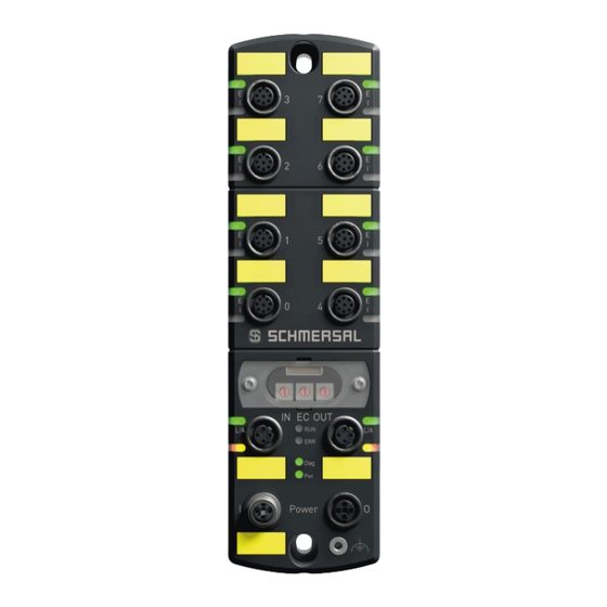
2.1 Module description 2.1.1 Purpose, ordering code, module overview The SFB-EC-8M12-IOP safety fieldbox is designed for connection of up to 8 safety switchgear units with parallel IO signals to a EtherCAT® / FSoE network. A maximum of 4 BDF200-FB control panels can be connected to the device ports X4 –... - Page 10 Module overview Device ports X0 – X3 Device ports X4 – X7 FB-Interface for BDF200-FB Error-LED X3 Error-LED X7 Device port X3 Device port X7 Input-LED X3 Input-LED X7 Error-LED X2 Error-LED X6 Device port X2 Device port X6 Input-LED X2 Input-LED X6 Error-LED X1 Error-LED X5...
- Page 11 2.1.2 Safety inputs and test pulse outputs The SFB-EC-8M12-IOP has two safety inputs and two test pulse outputs for the supply of dry contacts at each of the 8 device ports X0 - X7. These safety inputs are usable for:...
- Page 12 2.1.4 Diagnostic input / FB interface The SFB-EC-8M12-IOP has one diagnostic input at each of the 8 device ports X0 - X7 for status signals of the connected safety switchgear. At the 4 device ports X4 - X7 a FB interface is additionally integrated on this input.
- Page 13 2.1.6 EtherCAT® Linear topology The SFB-EC supports the Linear topology. INFORMATION Further information about the configuration of Linear topology can be found in the documentation of your EtherCAT® Master. 2 Product description...
- Page 14 2.1.7 System Layout SFB-EC A typical system layout with the wiring of the safety switchgears is shown in the figure below. Power 24 VDC INFORMATION Further information about the connection of the different safety switchgear can be found in chapter 2.2 and 2.3.
- Page 15 Safety-Relay-Modules (SRB-E) with 2 channel safety inputs WARNING For safety switchgear with electronic OSSDs, cross fault detection of the device connection cable must be carried out by the safety switchgear! The SFB-EC monitors the test pulses on the outputs of the safety switchgear. 2 Product description...
- Page 16 Parameter data set Type C, safety monitoring 1oo2 Cross fault detection: ON / SFB handles cross fault detection. for electromechanics safety switches and sensors with 2 NC contacts − − for electromechanics solenoid interlocks with 2 NC contacts and 1 wire control of the unlocking function Parameter data set Type D, safety monitoring 1oo1 Cross fault detection: ON / SFB handles cross fault detection.
- Page 17 Operation of the stable time filter when using 1 channel safety inputs − The stable time filter effects a debounce function for the input signal. − If the contact is switched on for the first time, the monitoring time is started. −...
- Page 18 Inputs X1 & X2 − up to Cat 4 / PL e / SIL 3 Output DO: − SCHMERSAL devices: CSS range, RSS range, … 2.3.2 Electronic safety sensor / AOPD, 4/5-pole M12 connector Type A: Safety sensor with electronic OSSD, monitoring 1oo2...
- Page 19 − up to Cat 4 / PL e / SIL 3 Output DO: − up to Cat 3 / PL d / SIL 2 SCHMERSAL devices: MZM 100, AZM 200, AZM 201, AZM 300, AZM 40, … 2.3.4 Electronic safety interlock, interlock function via 2 wires...
- Page 20 − up to Cat 4 / PL e / SIL 3 Output DO: − up to Cat 3 / PL d / SIL 2 SCHMERSAL devices: AZM 161-FB, AZM 170-FB, AZM 150-ST, … WARNING For safety switchgear with dry contacts, cross-fault detection must be activated ! Set to parameter type C.
- Page 21 − up to Cat 4 / PL e / SIL 3 Output DO: − up to Cat 3 / PL d / SIL 2 SCHMERSAL devices: AZ range, PS range, BDF 100-NH(K), ZQ range, … WARNING For safety switchgear with dry contacts, cross-fault detection must be activated ! Set to parameter type C.
- Page 22 The safety output Y1 can be loaded with a maximum of 15 mA. All SCHMERSAL Safety-Relay-Modules of the SRB-E series with 2 inputs for pulsed 24V signals up to a load of < 15 mA can be connected. (e.g. SRB-E-301ST, SRB-E-201ST/LC, etc.)
- Page 23 Monitoring time Stable time 0.1 s Safety classification Inputs X1 & X2 − up to Cat 4 / PL e / SIL 3 Output DO: − SCHMERSAL devices: SLC 440-COM range, SLG 440-COM range, SLB 440 range, … 2 Product description...
-
Page 24: Technical Data
Power I/O M12-POWER / 4-pole, T-coded EtherCAT® IN/OUT M12 / 4-pole, D-coded M12 connector tightening torque min. 0.8 Nm / max. 1.5 Nm Recommended for SCHMERSAL cables 1.0 Nm Fixing screws 2x M6 Tightening torque max. 3.0 Nm Viewing window screws... - Page 25 2.4.2 Electrical Data Designation Value Electrical Data – Power I / O Supply voltage U 24 VDC -15% / +10% (stabilised PELV mains unit) Rated operating voltage U 24 VDC Current consumption SFB 200 mA Rated operating current I 10 A (external fuse protection required) Device fuse rating ≤...
-
Page 26: Safety Classification
Designation Value Diagnostic input / FB interface Switching thresholds - 3 V … 5 V (Low) 13 V … 30 V (High) Current consumption per input < 12 mA / 24 V Permissible residual drive current < 1.0 mA Input debounce filter 10 ms FB interface data transmission rate 19.2 kBaud... - Page 27 2.5.2 Safety inputs 1-channel Designation Value Standards EN ISO 13849-1, IEC 61508, EN 62061 Category 90 % 2.3 x 10 2.0 x 10 suitable for SIL 1 applications Mission time 20 years Response time of local safety input > EtherCAT 30 ms Test interval for error detection 10 s...
- Page 28 (see operating instruction actuator) WARNING In addition to the maximum reaction times of the SFB-EC, the reaction times of the connected safety switchgear, the configured watchdog time of the communication, the reaction time of the safety logic, the reaction time of output and the reaction times of other components, as for example actuators, must be taken into calculation.
- Page 29 Recommended setting for EtherCAT cycle times ≤ 1 ms: 30 ms ! INFORMATION The minimum watchdog time for the SFB-EC is calculated as follows: SFB ACK-Time (25 ms) + 4x set EtherCAT cycle time EtherCAT cycle times > 100 ms are not supported ! The watchdog time (WD-Com) must be calculated twice for the SFRT, because the safety outputs are also controlled via the EtherCAT®.
- Page 30 Calculation of the "Safety Function Response Time" (SFRT) Example: Calculation of the "Safety Function Response Time" (SFRT) for a Safety Input Function of the SFB-EC: Based on: Cycle time EtherCAT: 1 ms RT-Com: 4 ms WD_Time FSoE-Master: 30 ms RT-Sensor:...
-
Page 31: Installation
3 Installation 3.1 Mounting CAUTION The field box must be installed in a way that only authorised specialist personnel can access it. 3.1.1 General mounting instructions Fasten fieldbox with two M6-screws on a flat mounting surface, for mechanically strain-free installation. The maximum tightening torque is 3.0 Nm. Any mounting position. -
Page 32: Further Accessories
Dispose of the safety fieldbox properly in accordance with national regulations and laws. 3.1.4 Accessories INFORMATION Further accessories can be found under the search term "SFB-EC" in the Schmersal Online Catalogue at products.schmersal.com. Pre-wired and connecting cables Description Length [m] Type designation... -
Page 33: Electrical Connection
In case of a fault, a voltage of up to 60 V can be applied to the device ports. 3.2.2 Notes for replacing the device To replace a defective SFB-EC, follow the steps below: • Bring the machine and the SFB into a de-energized state • Disconnect all cables and dismount the old device. - Page 34 3.2.3 Overview of connections and LED indicators Device ports X0 – X3 Device ports X4 – X7 FB-Interface for BDF200-FB Error-LED X3 Error-LED X7 Device port X3 Device port X7 Input-LED X3 Input-LED X7 Error-LED X2 Error-LED X6 Device port X2 Device port X6 Input-LED X2 Input-LED X6...
- Page 35 3.2.4 Power supply and fuse protection The supply voltage of the safety fieldbox is to be protected with a fuse of 10 A. In order to increase the cable cross section for the supply voltage of the fieldbox, both connections from Us and GND must be connected in parallel. Pins 1 + 4 and 2 + 3 in the fieldbox are bridged.
- Page 36 Signal Description of fieldbox signals Transmit-Data + Receive-Data + Transmit-Data - Receive Data - Flange Ethernet shielding Colour code of the SCHMERSAL M12 cables, acc. DIN 47100 M12, 4-pin M12, 8-pin Wire colour Wire colour Wire colour Brown White Grey...
-
Page 37: Led Diagnostic Indicators
3.3 LED diagnostic indicators 3.3.1 LED indicators, device ports X0 – X7 There are 2 LED indicators on each device port. A green/red error LED and a yellow input LED to display the switching condition at the safety inputs. Error LED device ports (E) The error LED may exhibit the following display and flashing pattern: Display Description... - Page 38 Green, ON Link active, but no data exchange Green, n Flash PHY Auto Negoitation Error 3.3.3 Central LED indicators of SFB-EC There are 4 LEDs for central diagnostics of the fieldbox: (RUN) = green LED for EtherCAT RUN status −...
- Page 39 EtherCAT® ERROR status LED (ERR) The ERR LED shows the error state of the EtherCAT-State-Machine. The ERROR status LED may exhibit the following display and flashing pattern: Display Description No Error SFB operates without error Red, flashes Invalid Configuration General Configuration Error Red, Local Error Single Flash...
-
Page 40: Set-Up And Maintenance
4 Set-up 4.1 Set-up and maintenance 4.1.1 Set-up A check must be carried out to ensure that the projected safety function is effective. WARNING The safety functions, configuration of the safety fieldbox and correct installation must be checked by a responsible safety specialist/safety representative. 4.1.2 Maintenance The safety fieldbox operates maintenance-free if installed and used properly. -
Page 41: Project Engineering
4.2 Configuration of the SFB-EC 4.2.1 Project engineering The project engineering of the SFB-EC in TwinCAT is done in two data areas: Cyclic data (PDO) The cyclic communication transports the safety I/O data and the functional status information via the corresponding “Process Data Object” (PDO). - Page 42 4.2.2 Install ESI file The device data required for project planning is saved in ESI files (EtherCAT Slave Information). You will find the ESI file for the SFB-EC: Online at www.products.schmersal.com / search keyword "SFB-EC" − − Downloadable from device via the web server info page (Refer to chapter 6) the documentation of your EtherCAT®...
- Page 43 4.2.3 Connecting EtherCAT® Master with TwinCAT Create the connection with your EtherCAT® Master (target system) in the TwinCAT user interface. Choose the relevant device in the dialog and confirm with OK. If the device is not listed, it can be searched for in the network via the "Search (Ethernet)"...
- Page 44 4.2.4 Activate TwinCAT Config Mode Changes to the configuration of the devices can only be made in TwinCAT if Config Mode has been activated. Select the Config Mode menu item from the menu bar or click on the icon in the toolbar. The symbol at the lower right side of the status bar gives information about the operating mode of the Master.
- Page 45 4.2.5 Device scan EtherCAT® devices Via a device scan all connected EtherCAT® devices can be listed in their correct topology. This method only works if the system structure is already complete and the devices can be accessed online. Right-click on "Devices" in the Solution Explorer and select the "Scan" option. Depending on the Master device the Ethernet interface of the Master must be selected: Select here „Device 2 (EtherCAT)“.
- Page 46 The following automatic request "Scan for Boxes" can be confirmed with "Yes”. The Free Run mode can be activated after a scan. After scanning, all devices are displayed in the Solution Explorer hierarchy. 4 Set-up...
- Page 47 INFORMATION If devices are already present, TwinCAT shows the changes compared to the configuration in a comparison view. By the option ">> Copy All >>" the scanned device configuration can be transferred. If the selection is identical, the selection is green or a corresponding message is displayed.
- Page 48 4.2.6 Manual adding EtherCAT® Device An EtherCAT® device can also be added manually to the configuration. For this click with the right mouse button in the Solution Explorer on the EtherCAT® Master and select "Add New Item". In the selection, the SFB can be found by navigation or by using the "Search" field. Select the device and click OK.
- Page 49 Select the menu item "Mailbox -> EoE" in the opened dialog. After a scan, the IP address of the gateway (= Ethernet port of the CX) is already entered. The IP address of the SFB-EC is still not valid. 4 Set-up...
- Page 50 Enter a valid IP address for the SFB-EC. The web page of the device can now be accessed via an Internet browser. The EoE service can be disabled by deselecting the "Virtual Ethernet Port" option. INFORMATION If an external device is used as an EtherCAT® master (e.g. Beckhoff CX), it must be configured as a TCP/IP gateway in order to achieve external access to a device in the EtherCAT®...
- Page 51 4.2.8 Link Acknowledge Fault The signal Acknowledge Fault is provided as PDO of the SFB to acknowledge present faults. It is necessary during project engineering and must be linked to an input. Select "Acknowledge Fault global" of the SFB in the Solution Explorer. Select the "Linked to..."...
- Page 52 4.2.9 Free Run Mode The "Free Run" option switches the EtherCAT fieldbus to OP status and communication with the devices starts. In contrast to the “Run” mode the "Free Run" has no real-time character and is only suitable for commissioning. In the menu item of the EtherCAT master "Device 2 (EtherCAT)"...
- Page 53 4.2.10 Run Mode TwinCAT can be set to real-time mode via the Run Mode button. WARNING In Run mode, only devices that are used in at least one task are updated. If no task is created in the project besides the I/O Idle task, no data exchange is executed.
- Page 54 The task now contains a new variable that can be linked to a device so that com- munication takes place in real-time mode. Select the variable and click on "Linked to...". Select an input of the SFB and click OK. INFORMATION It may be necessary to adjust the filters on the right side of the "Link"...
- Page 55 • Switch SFB-EC de-energized • Select TwinSAFE address • Close the viewing window again • Supply SFB-EC with power again WARNING The safety functions, configuration of the safety fieldbox and correct installation must be checked by a responsible safety administrator / safety representative.
- Page 56 4.2.12 Create a TwinSAFE project To set up a FSoE connection the TwinSAFE extension within TwinCAT is necessary. Safety logic is inserted in a safety project. Each safety project is assigned to a target system as safety master, which executes the logic of the TwinSafeGroups. Devices can be inserted into a TwinSafeGroup as alias devices.
- Page 57 A preconfigured Safety project can now be found in the Solution Explorer. 4 Set-up...
- Page 58 4.2.13 Select FSoE Master Select the FSoE master (target system) on which the safety project is to run. Double-click on the "Target System" entry in the safety project. Select your connected FSoE master terminal (here EL6930). Click the Select button in the Physical Device section. Select / Link Select the corresponding master terminal from the project hierarchy in the dialog and confirm the selection with OK.
- Page 59 4.2.14 Inserting the FSoE connection Right-click on the "Alias Devices" element in the Safety project and select "Import Alias Device(s) from I/O-configuration". Select the FSoE module of the SFB and confirm the selection with OK. 4 Set-up...
- Page 60 Recommended setting for EtherCAT cycle times ≤ 1 ms: 30 ms ! INFORMATION The minimum watchdog time for the SFB-EC is calculated as follows: SFB ACK-Time (25 ms) + 4x set EtherCAT cycle time EtherCAT cycle times > 100 ms are not supported ! WARNING The watchdog time has a direct effect on the Safety response time.
- Page 61 4.2.16 Setting the safety parameters The safety parameters for the individual device connections of the SFB-EC are also stored in the FSoE master and sent to the device during startup. Double-click the alias device of the SFB in the safety project.
-
Page 62: Error Acknowledgement
Error Acknowledgement Insert a non-safe input as Error Acknowledgement for the group port. Double click on the "ErrorAcknowledgement" alias device. To do this, click on the Select button. Link this input bit to the desired digital input that is to be used for error acknowledgement. - Page 63 Run/Stop Insert a non-safety input as Run/Stop indicator for the corresponding Group Port. Right-click on "Alias Devices" and select "Add" -> "New Item...". Select "1 Digital Input (Standard)" in the following dialog and assign a name. In the example the name "RunStop" is selected, because this signal should release the RUN state.
- Page 64 4.2.18 Mapping of the Group Ports Double-click on the "TwinSafeGroup1" element in the safety project and select the "Variables" tab under "Variable Mapping" at the bottom. Here the alias device "Error Acknowledgement" is already preconfigured. Click on the drop-down button in the "Assignment" column of the "RunStop" alias device.
- Page 65 Select "RunStop" in the selection window under Alias Devices and select "Channel 1 - In". Confirm the selection with OK. The TwinSAFE Group is now configured and can be used. It is executed as long as the RunStop input is active. Errors can be reset via the Error Acknowledge input.
- Page 66 4.2.19 Programming of the safety logic To link the safe inputs and outputs of the different safety devices, proceed as follows: Double-click "TwinSafeGroup" in the Solution Explorer. Open the "Toolbox" to display various function blocks. INFORMATION If you do not see a toolbox, this window can be activated in the menu under "View"...
- Page 67 Drag and drop the element "safeDecouple" from the toolbox into the middle area of "Network1". Repeat the step to get a total of 2 decouple blocks. 4 Set-up...
- Page 68 Select "DecIn1" from "FBDecouple1". Select a variable name in the properties (here "iInX0"). Create a name for the output DecOut1 at FBDecouple2 (here "oDOX0"). HINWEIS If you do not see the "Properties" window, it can be activated via the "View" menu or by pressing "F4".
- Page 69 In the "Variable Mapping" -> "Variables" area, now link both variables with an input respectively output of the SFB. Input mapping Output mapping 4 Set-up...
- Page 70 4.2.20 Download Safety Project The Safety project is executed inside the FSoE Master and must first be compiled and downloaded. INFORMATION Further information about downloading a “Safety Project” can be found in the documentation of your FSoE Master. Example FSoE Master terminal Navigate to Safety Target System and note or copy the serial number of the FSoE master terminal.
- Page 71 4.2.21 FSoE Diagnosis The following chapters show different ways to diagnose a Safety Connection. FSoE PDOs The state of a FSoE connection can be diagnosed inside their PDOs: The first byte of the PDO provides information about the FSoE state. - "36"...
- Page 72 TwinSAFE View The TwinSAFE Group supports an online view in which the states of the FSoE connections as well as the data can be analyzed. Double-click on the TwinSafeGroup in your safety project. Select the button "Show Online Data" in the toolbar or via the TwinSAFE menu. The TwinSAFE view now changes and shows the status and signals.
- Page 73 In the list in the lower part, more detailed information on the individual TwinSAFE groups, alias devices and I/Os can be found under the "Safety Project Online View" tab. 4 Set-up...
- Page 74 4.3 Data Layout SFB-EC 4.3.1 Cyclic data (PDO) The cyclic communication transports the safety I/O data and the functional status information via the corresponding Process Data Object (PDO). The direction of the data to be transferred is always defined from the PLC's point of view.
- Page 75 The bit assignment of the data bytes in the individual PDO are described below. Module 1 / FSoE Data, Safety Input data (SFB => PLC) Module 1 (FSoE (4 Byte I/O)) Data Label [Type] SFB Data Signal Safety Input Data Safety Input X1/X2 FSoE Inputs [BIT]...
- Page 76 Module 2 / Functional Data, Input data (SFB => PLC) / Output data (PLC => SFB) Module 2 (Functional Data) Data Label [Type] SFB Data Signal Functional Input / Output Data Qualifier-Bit Device port Port Qualifier [BIT] Device port X0 Port X0.Qualifier 0 = Device port passivated Device port X1...
- Page 77 Module 3 / FB-I Data, Input data (SFB => PLC) Module 3 (FB-I Data) Data Label [Type] FB-Interface Data Signal FB-Interface Input Data FB-I Response data from device at X4 FB-I Port 4 Inputs [BIT] E-STOP not actuated Port X4.E-STOP not actuated 0/1 = FB-I response bits BDF200 NO contact Pos.
- Page 78 Module 3 / FB-I Data, Output data (PLC => SFB) Module 3 (FB-I Data) Data Label [Type] FB-Interface Data Signal FB-Interface Output Data FB-I Request data for device at X4 FB-I Port 4 Outputs [BIT] LED G24 Signal lamp red Port X4.G24 signal lamp RED 0/1 = FB-I request bits BDF200 LED G24 Signal lamp green...
- Page 79 EtherCAT®. For this a mailbox procedure is used, with which the EtherCAT master can exchange data with an EtherCAT slave. The SFB-EC transmits the diagnostic history, the device slot parameters, the mod- ule status and a timestamp in the "CANopen over EtherCAT" (CoE) service.
- Page 80 Current Timestamp The current timestamp in “nano-seconds after power ON of the SFB-EC” can be read out separately. Name: Timestamp Index: 0x10F8 Sub- Content / Data Description Datatype Index Value Timestamp in ns after Power ON of the SFB UINT64...
- Page 81 Sub- Content / Data Description Datatype Index Number of Subindices UINT8 Internal Current Timestamp of SFB-EC UINT32 Status module: Bit 0: 1 = RUN UINT8 Bit 0: 0 = Module fault active Status device ports: Bit 1: 1 = OK...
-
Page 82: Diagnostic System
5 Diagnostic system 5.1 SFB-EC Diagnostics The safety fieldbox SFB-EC can detect module faults and device port faults. In case of module faults, the SFB-EC is completely passivated. Module faults are for example, over temperature of the SFB, under voltage or internal module faults. - Page 83 5.1.2 Diagnostic messages Device-Port faults The "Device-Port passivated" status indicates that a device port has been switched to the safety state due to a fault. Error No. Error message Status Device-Ports Device-Port X0 passivated, see message single error at X0 Device-Port X1 passivated, see message single error at X1 Device-Port X2 passivated, see message single error at X2 Device-Port X3 passivated, see message single error at X3...
- Page 84 Error No. Error message Fault Safety-Inputs Fault on Safety inputs Device-Port X0, check parameter cross-wire monitoring and wiring Fault on Safety inputs Device-Port X1, check parameter cross-wire monitoring and wiring Fault on Safety inputs Device-Port X2, check parameter cross-wire monitoring and wiring Fault on Safety inputs Device-Port X3, check parameter cross-wire monitoring and wiring Fault on Safety inputs Device-Port X4, check parameter cross-wire monitoring and wiring Fault on Safety inputs Device-Port X5, check parameter cross-wire monitoring and wiring...
- Page 85 Error No. Error message Fault Pulse-Outputs Fault on pulse outputs Device-Port X0, check wiring Fault on pulse outputs Device-Port X1, check wiring Fault on pulse outputs Device-Port X2, check wiring Fault on pulse outputs Device-Port X3, check wiring Fault on pulse outputs Device-Port X4, check wiring Fault on pulse outputs Device-Port X5, check wiring Fault on pulse outputs Device-Port X6, check wiring Fault on pulse outputs Device-Port X7, check wiring...
- Page 86 Error No. Error message Overload fault Digital-Output Overload digital output Device-Port X0, check load and wiring Overload digital output Device-Port X1, check load and wiring Overload digital output Device-Port X2, check load and wiring Overload digital output Device-Port X3, check load and wiring Overload digital output Device-Port X4, check load and wiring Overload digital output Device-Port X5, check load and wiring Overload digital output Device-Port X6, check load and wiring...
- Page 87 Error No. Error message Discrepancy- / Stable time fault Discrepancy / stable time error Device-Port X0, check parameter stable time filter and safety guard Discrepancy / stable time error Device-Port X0, check parameter stable time filter and safety guard Discrepancy / stable time error Device-Port X0, check parameter stable time filter and safety guard Discrepancy / stable time error Device-Port X0, check parameter stable time filter and safety guard...
- Page 88 5.2.1 Module error If a module error is detected, the SFB-EC responds as follows: − The SFB is completely passivated, i.e. all 8 device ports are passivated. All input and output data are set to "0".
- Page 89 The system reacts according to the responses defined in the FSoE specification. In the event of an error in the safety related communication, all input and output data of the SFB-EC are set to "0" and the module remains passivated until the error in the communication has been corrected.
- Page 90 5.3 Acknowledgement corrected faults 5.3.1 Acknowledgement module faults If a module error is detected, all device ports are passivated. (Refer to chapter 5.2.1) An acknowledge request is sent when the detected module fault is removed and when no further module fault is detected. Acknowledgement Request: (Request acknowledgement - Module 2 (Functional Data), refer to chapter 4.3.1)
- Page 91 Acknowledgement with global acknowledgement pulse The real acknowledgement is done via an acknowledgement pulse of 500 ms (+/- 150 ms) which is sent from the PLC to the SFB-EC. The pulse always globally acknowledges all removed module faults and device port faults ! Faults that have not yet been removed are not acknowledged.
-
Page 92: Web Server
6 Web Server 6.1 Description Web server A web server for displaying status and diagnostic data is integrated in the SFB-EC. To access the WebServer of the SFB, the IP settings of the device must be set in the EoE service. - Page 93 6.1.1 Page: SFB Home The "SFB Home" page displays an overview of the most important status, network and device data. Pos. Graphic Definition Description Language The language of the display can be changed between German and English with the language buttons. Blink SFB The "Blink SFB"...
- Page 94 The "Diagnostics" page displays the fault messages that the field box has sent to the PLC. The fault messages should be stored in the controller. The SFB-EC stores these fault messages only so long as switched on. Each fault message is displayed with a time stamp, a status icon, the fault number and the fault description.
- Page 95 6.1.3 Page: Status Device Ports The "Status Device Ports" page displays the fault status and I/O status of each device port. The meaning of the colours of the status indicators are explained on the "Help" page. (Refer to chapter 6.1.5) 6 Web Server...
- Page 96 6.1.4 Page: Parameters The "Parameters" page displays the “Configuration Type” and the set parameter values from each device port. If the SFB-EC has not been parameterized yet, the parameter values are empty! 6 Web Server...
- Page 97 6.1.5 Page: Help The "Help" page shows the meaning of the colours of all status displays on the web server. In addition, the limit values are displayed for the supply voltage and the field box temperature. 6 Web Server...
- Page 98 6.1.6 Page: Info The "Info" page shows the type designation, the order number and the support address of Schmersal. The ESI file saved in the field box can be downloaded using the "Download ESI File" button. 6 Web Server...
- Page 99 However, if the power supply is looped through from field box to field box, the maximum ratings given below apply. Three different configurations are shown for each of the different SCHMERSAL devices. One configuration with long cable lengths (maximum), one configuration with medium cable lengths (medium) and one configuration with shorter cable lengths (small).
- Page 100 Device / Max. Number Length of cable (A) Length of cables (B) Length of cables (C) configuration number of of field until 1st field box between the field boxes for device connection version devices boxes AZM 201 / Maximum 10.0 m 10.0 m 7.5 m AZM 201 / Medium...
-
Page 101: Eu Declaration Of Conformity
7.2 EU Declaration of conformity INFORMATION The currently valid declaration of conformity can be downloaded from the internet at www.products.schmersal.com 7 Annex... - Page 102 K. A. Schmersal GmbH & Co. KG Möddinghofe 30, D - 42279 Wuppertal Germany Phone: +49 - (0)2 02 - 64 74 - 0 Telefax: +49 - (0)2 02 - 64 74 - 1 00 E-Mail: info@schmersal.com Internet: www.schmersal.com Subject to technical changes, all data without liability.
Need help?
Do you have a question about the SFB-EC and is the answer not in the manual?
Questions and answers