Table of Contents
Advertisement
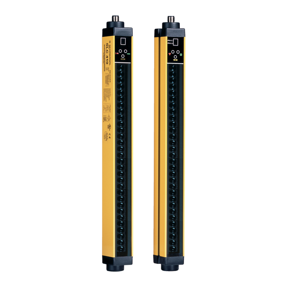
SLC 410 / SLG 410
MOUNTING AND WIRING INSTRUCTIONS
TABLE OF CONTENTS
INTRODUCTION ........................................................................................................................2
OPERATION...............................................................................................................................3
INSTALLATION ..........................................................................................................................4
POSITION........................................................................................................................... 5
SAFETY DISTANCE CALCULATION .................................................................................... 6
VERTICAL POSITION OF THE BARRIER............................................................................. 7
HORIZONTAL POSITION OF THE BARRIER........................................................................ 8
ELECTRICAL CONNECTIONS ............................................................................................. 9
MULTIPLE SYSTEMS........................................................................................................ 12
DISTANCE BETWEEN REFLECTING SURFACES ............................................................. 12
USE OF DEFLECTION MIRRORS ...................................................................................... 14
MECHANICAL ASSEMBLY AND OPTIC ALIGNMENT......................................................... 15
OPERATION AND TECHNICAL DATA ...................................................................................16
SIGNALS .......................................................................................................................... 16
TEST FUNCTION .............................................................................................................. 17
OUTPUTS STATUS ........................................................................................................... 17
TECHNICAL SPECIFICATIONS ......................................................................................... 18
DIMENSIONS ..........................................................................................................................19
CHECKS AND MAINTENANCE...............................................................................................21
TROUBLESHOOTING ....................................................................................................... 22
SPARE PARTS.........................................................................................................................23
PHOTOELECTRIC
SAFETY
BARRIER
SLC 410 / SLG 410
Advertisement
Table of Contents

Related Manuals for schmersal SLC 410


Summary of Contents for schmersal SLC 410
-
Page 1: Table Of Contents
SLC 410 / SLG 410 PHOTOELECTRIC SAFETY BARRIER SLC 410 / SLG 410 MOUNTING AND WIRING INSTRUCTIONS TABLE OF CONTENTS INTRODUCTION ........................2 OPERATION..........................3 INSTALLATION ..........................4 POSITION........................... 5 SAFETY DISTANCE CALCULATION ..................6 VERTICAL POSITION OF THE BARRIER................7 HORIZONTAL POSITION OF THE BARRIER................ 8 ELECTRICAL CONNECTIONS ..................... -
Page 2: Introduction
The SLC 410 / SLG 410 photoelectric barrier is a optoelectronic safety system. It belongs to the family of Type 4 according to EN 954-1. The SLC 410 / SLG 410 barrier, which consists of an Emitter and a Receiver, is a type 4 optoelectronic safety device according to standards EN 61496-1 and EN 61496-2. -
Page 3: Operation
If the latter is placed horizontally, this value refers to the depth of the protected area. The working range is the maximum operative distance that can exist between the Emitter and the Receiver. SLC 410 / SLG 410 is available with the following resolutions: – 14 mm (protected height from 150 mm to 1800 mm) PROTECTION OF FINGERS –... -
Page 4: Installation
INSTALLATION Before installing the SLC 410 / SLG 410 safety system, make sure that: The safety system is only used as a stopping device and not as a machine control device. The machine control can be actuated electrically. All dangerous machine movements can be interrupted immediately. In particular, the machine stopping times must be known and, if necessary, measured. -
Page 5: Position
The recommended Cf factors are shown in the table below: ENVIRONMENTAL CONDITION CORRECTION FACTOR Cf 0.25 Steam 0.50 Dust 0.50 Dense fumes 0.25 If the device is installed in places that are subject to sudden changes in temperature, the appropriate precautions must be taken in order to prevent the formation of condensation on the lenses, which could have an adverse effect on monitoring. -
Page 6: Safety Distance Calculation
SAFETY DISTANCE CALCULATION The barrier must be installed at a distance that is greater than or equal to the minimum safety distance S, so that a dangerous point can only be reached after all hazardous machine movements have stopped (Figure 3). According to European standard EN999, the minimum safety distance S must be calculated using the following formula: S = K (t... -
Page 7: Vertical Position Of The Barrier
VERTICAL POSITION OF THE BARRIER 14 mm resolution models These models are suitable for the protection of fingers. S = K (t ) + C and S > 100 mm point of safety barrier danger 30 mm resolution models These models are suitable for the protection of hands. -
Page 8: Horizontal Position Of The Barrier
Multibeam Models. point of danger These models are suitable for the protection of the entire body and must not be used to protect arms or legs. safety barrier The minimum safety distance S is calculated according to the following formula: S = K * (t ) + C direction... -
Page 9: Electrical Connections
ELECTRICAL CONNECTIONS WARNINGS Before making the electrical connections, make sure that the supply voltage complies with the one specified in the technical data sheet. Emitter and Receiver units must be supplied with PELV type 24V ± 20% power supply (e.g. by means of an insulating transformer according to EN 60724). The external power supply must comply with EN 60204 (it can bridge short-term mains failures of up 20 msec). - Page 10 Connector pins EMITTER RECEIVER Figure 8 EMITTER NUMBER NAME MEANING 24 V Power supply (positive) 2 (see table 2) SEL RANGE/TEST1 Input 1 for range / TEST selection Power supply (negative) 4 (see table 2) SEL RANGE/TEST2 Input 2 for range / TEST selection Ground connection Table 1 RANGE and TEST SELECTION...
- Page 11 Example of connection of the SLC 410 / SLG 410 barrier to the SCR 1R1 safety module Colour code: brown white blue black grey Refer to table 2, page 10 for the correct connection of pins 2 and 4 Figure 9 Warnings regarding the connection cables •...
-
Page 12: Multiple Systems
MULTIPLE SYSTEMS When more than one SLC 410 / SLG 410 system is used, precautions must be taken to avoid optical interference between them: install units so that the beam emitted by the Emitter of one system can only be received by the relative Receiver. - Page 13 Figure 12 illustrates the values for the minimum distance d that must be maintained when the distance l between the Emitter and Receiver is changed. Figure 12 After installing the system, check whether any reflecting surfaces intercept the beams, first in the centre and then in the vicinity of the Emitter and Receiver.
-
Page 14: Use Of Deflection Mirrors
USE OF DEFLECTION MIRRORS In order to protect or control areas that can be accessed from more than one side, to the Emitter and Receiver in addition, one or more deflection mirrors can be installed. These mirrors enable the optical beams generated by the Emitter to be deviated on one or more sides. -
Page 15: Mechanical Assembly And Optic Alignment
MECHANICAL ASSEMBLY AND OPTIC ALIGNMENT The Emitter and the Receiver must be assembled opposite each other. Use the fastening brackets and inserts supplied with the system to place the Emitter and the Receiver so that these are aligned and parallel to each other and with the connectors facing the same way. Perfect alignment of the Emitter and Receiver is essential in order to assure correct barrier operation. -
Page 16: Operation And Technical Data
OPERATION AND TECHNICAL DATA SIGNALS COLOUR STATUS DISPLAY (4) CONDITION Yellow System activated. Initial TEST. Yellow TEST condition Green Green Normal operation, low range Green Normal operation, high range F + fault code Malfunction * from 1 to 3 COLOUR STATUS DISPLAY (8) CONDITION... -
Page 17: Test Function
The minimum duration of the TEST function must be 80 msec. OUTPUTS STATUS The SLC 410 / SLG 410 features two semiconductor outputs on the Receiver, the status of which depends on the condition of the protected area. The maximum load allowed is 500 mA a t 24 V , which corresponds to a resistive load of 48Ω. -
Page 18: Technical Specifications
TECHNICAL SPECIFICATIONS TECHNICAL SPECIFICATIONS OF SLC 410 / SLG 410 BARRIERS Protected height 160 – 1810 Resolutions 14 – 30 –50 0 - 2 (low) Working range (selectable) 14mm models 0 - 5 (high) Working range (selectable) 0 - 6 (low) -
Page 19: Dimensions
DIMENSIONS (in mm) Figure 17 Emitter and Receiver SLC-410 E/Rxxxx-xx-12 0160 0310 0460 0610 0760 0910 1060 1210 1360 1510 1660 1810 1001 1151 1301 1451 1601 1751 1901 1060 1210 1360 1510 1660 1810 (PROTECTED AREA) Mounting 2 mounting kits 3 mounting kits SLG-410-E/Rxxxx-xx-12 0500-02 0800-03 0900-04... - Page 20 inserts M8 Type SMB 250 SMB 370 SMB 540 SMB 715 SMB 885 SMB 1060 1060 SMB 1230 1230 SMB 1400 1400 SMB 1575 1575 SMB 1750 1750 SMB 1900 1900 Figure 19 Fastening brackets for deviation mirrors Figure 20 Deviation mirrors...
-
Page 21: Checks And Maintenance
Make sure that during each stage of the test object’s movements the red LED on the Receiver is permanently on. Figure 21 The SLC 410 / SLG 410 barrier does not require any specific maintenance operations; however, periodic cleaning of the front protective surfaces of the Emitter and Receiver optics is recommended. -
Page 22: Troubleshooting
Check the connection of terminals 2 and 4 (SEL RANGE/TEST) SEL RANGE/TEST on the connector. signals 2, 3 Internal system failure Return the equipment to the K.A. Schmersal GmbH for repair. RECEIVER CODE DIAGNOSIS REMEDY DISPLAYED Overcurrent on one or... -
Page 23: Spare Parts
MS LC-01 Mounting set with 2 mounting kits 1666713100 MS LC-02 Mounting set with 3 mounting kits 1666713110 Specifications subject to change without warning. • No part of this manual may be reproduced without the prior consent of K.A. Schmersal GmbH.
Need help?
Do you have a question about the SLC 410 and is the answer not in the manual?
Questions and answers