Advertisement
Available languages
Available languages
Quick Links
SOLAR INVERTER WITH LCD DISPLAY &
MODEL
VT-6605305
VT-6608305
VT-6610305
Thank you for selecting and buying V-TAC Product. V-TAC will serve you
the best. Please read these instructions carefully & keep this user manual
handy for future reference. If you have any another query, please contact
our dealer or local vendor from whom you have purchased the product.
They are trained and ready to serve you at the best.
IN CASE OF ANY QUERY/ISSUE WITH THE PRODUCT, PLEASE REACH OUT TO US AT: SUPPORT@V-TAC.EU
FOR MORE PRODUCTS RANGE, INQUIRY PLEASE CONTACT OUR DISTRIBUTOR OR NEAREST
DEALERS. V-TAC EUROPE LTD. BULGARIA, PLOVDIV 4000, BUL.L.KARAVELOW 9B
INSTRUCTION MANUAL
DC SWITCH -THREE PHASE
SKU
11371
11372
11373
INTRODUCTION
Multi-Language Manual QR CODE
Please scan the QR code to access the manual
in multiple languages.
Advertisement

Subscribe to Our Youtube Channel
Related Manuals for V-TAC VT-6605305


Summary of Contents for V-TAC VT-6605305
- Page 1 Please scan the QR code to access the manual in multiple languages. IN CASE OF ANY QUERY/ISSUE WITH THE PRODUCT, PLEASE REACH OUT TO US AT: SUPPORT@V-TAC.EU FOR MORE PRODUCTS RANGE, INQUIRY PLEASE CONTACT OUR DISTRIBUTOR OR NEAREST DEALERS. V-TAC EUROPE LTD. BULGARIA, PLOVDIV 4000, BUL.L.KARAVELOW 9B...
- Page 2 WARNING 1. Please make sure to turn off the power before starting the installation. 2. Installation must be performed by a qualified electrician. 3. Proper grounding should be ensured throughout the installation. This marking indicates that this Caution, risk of product should not be disposed electric shock.
- Page 3 SAFETY GUIDELINES After receiving this product, first ma ke sure that the product is well packaged. If you have any questions, please contact the shipping company or local distributor immediately. Installation of PV inverters must be performed by professional technician who has been specially trained, thoroughly read and familiar with all the contents of this manual and familiar with the safety requirements of the electrical system.
- Page 4 WHAT TO DO AFTER SCRAPPING Do not dispose of the inverter together with household waste. The user has the responsibility and obligation to send it to the designated organization for recycling and disposal. DELIVERY AND INSTALLATION Keep the package and unit complete, dry and clean during storage and delivery.
- Page 5 MAINTENANCE AND INSPECTION Only qualified electricians are allowed to perform the mainte- nance, inspection, and components replacement of the inverter. Contact with the local dealer or supplier for maintenance. In order to avoid irrelevant personnel from entering the mainte- ...
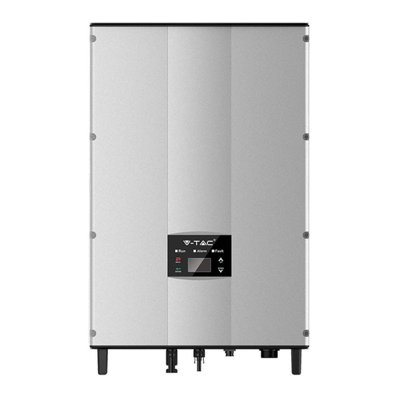
- Page 6 The recommended solar modules need to comply with IEC61730 Class A standard. SUPPORTED GRID CONNECTION STRUCTURE The series grid-tied solar inverters support TN-S, TN-C, TN-C-S and TT grid connection. When applied to the TT connection, the N-to-PE voltage should be less than 30V. Figure 2 Type of grid PRODUCT APPEARANCE Figure 3 Products appearance...
- Page 7 PARTS INSTRUCTION Na me Instruc tion Cover Operational panel LED status light, LCD display, keypad DC switc h On–off of the DC input (optional) DC input port For the c onnec tion of solar modules Communication port RS485 and EXT c ommunication port AC terminal For the c onnec tion of AC output Cooling chamber...
- Page 8 ICONS CERTIFICATION Icons Instruction TUV certification mark. The inverter is certified by TUV. CE certification mark. The inverter complies with the CE directive. CQC certification mark. The inverter is certified by CQC. EU WEEE mark. Cannot dispose of the inverter as household waste. PRODUCTS MODULES Table of the grid-tied solar inverter Product name...
- Page 9 DIMENSIONS AND WEIGHT Figure 5 Inverter dimensions Table of inverter dimension and net weight Model H (mm) W (mm) D (mm) Net weight (kg) 4kW / 4kW–S / 5kW / 5kW-S / 6kW 8kW / 10kW Figure 6 Paper packages dimension Table of packages dimension and gross weight Weight Packaging...
- Page 10 STORAGE If the inverter is not put into use immediately, the storage of inverter should meet the following requirements: • Do not remove the outer packing. • The inverter needs to be stored in a clean and dry place, and prevent the erosion of dust and water vapor.
- Page 11 Table of detailed delivery list of single-phase inverter Na me Q ua ntity 4kW / 4kW- S / 5kW / 5kW- S / 6kW / 8kW / 10kW inverter Installation brac ket Operation manual Assembling bolts M5*20 Expansion bolts M6*50 Communic ation c onnec tor DC c onnec tor 2 pairs / 1 pair(4kW- S、5kW- S)...
- Page 12 (2) The installation site must be well ventilated and away from raindrops or direct sunlight. (3) There must be enough pre-reserved space around the installation site for convenient disassemble of the inverter and air convection Figure 8 Installation space (4) The ambient temperature of installation should be -25°C~60°C. (5) The installation site should be away from electronic devices which can generate strong electromagnetic interference.
- Page 13 CABLE SPECIFICATION In order to regulate and compatible with the inverter AC/DC connector or terminal block specifications, below requirements on the AC/DC cable connected to corresponding inverter should be fulfilled: Table of cable specifications DC side AC side Min cross section Min cross-section Min cross section Inverter model...
- Page 14 Table of size of installation bracket Spacing of installation hole Inverter model A(mm)*B(mm) 4kW / 4kW-S / 5kW / 5kW-S / 6kW / 260*45 8kW / 10kW The procedures for installation of inverter are listed below: (1) Use the punch positioning plate in the packaging box to determine the punch position. As shown in Figure 10 Level the holes with a level ruler and mark it with a marking pen.
- Page 15 (4) Fix the installation bracket onto the expansion bolts and ensure the installation is firm enough(tightening torque is 13N•m) . As shown in Figure Figure 13 Fix the installation bracket (5) Hang the inverter onto the installation bracket and ensure the installation is firm enough.
- Page 16 WIRING INSTALLATION This section presents the detailed contents and safety precautions related to electrical connection. Fig 16 is the connection diagram for PV grid-connected system. Figure 16 PV grid-connected system diagram Electrical connection must be carried out by professional technicians as wrong operation may cause damage to the device, physical injuries or even death during system operation.
- Page 17 WIRING INSTALLATION Figure 17 MC4 DC connector and PV string connection The procedures for connecting PV string t to the inverter DC input are shown below : (1) Before connecting PV string to inverter, ensure proper measures against lightening and short circuit have been taken; ...
- Page 18 (4) Connect PV string to the inverter and ensure tightly-fastened (5) When removing the DC connector from the inverter, insert the head of the straight screwdriver into the raised hole in the middle of the connector, and force the movable end of the connector to exit.
- Page 19 OPERATION INSPECTION BEFORE OPERATION The following items must be checked strictly before running the PV grid-connected inverter (including but not limited to the following items): (1) Ensure the installation site meet the requirement mentioned in “before installation” for easy installation, removing, operation and maintenance. (2) Ensure the mechanical installation meet the requirement.
- Page 20 STOPPING When it is necessary to carry out power-off maintenance, inspection and fault elimination on the inverter, stop the inverter according to the following steps: (1) Disconnect the breaker on inverter public grid AC side; (2) Disconnect the integrated DC switch of the inverter; (3) Disconnect the switch on PV string DC input side;...
- Page 21 MAINTENANCE GUIDE CLEAN THE INVERTER Cleaning procedure is as follows: (1) Disconnect the input and output switches. (2) Wait ten minutes. (3) Clean the surface and air inlet/outlet of the inverter with soft brush or vacuum cleaner; (4) Repeat inspection before operation - operating content. (5) Restart the inverter.
- Page 22 (5) Clean the inverter cooling bin and fan with soft brush or vacuum cleaner. (6) Install the screws and covers of cooling bin or fan box to their original place. (7) Install the inverter to its original place again according to section installation. (8) Repeat the operations in section inspection before operation.
- Page 23 DISPLAY AND OPERATION PANEL This chapter describes the panel displaying and how to operate on the panel, which involves the LCD display, LED indicators and operation panel. LED INDICATORS There are three LED indicators on the panel: (1) “Run”, operation indicator, green; (2) “Warn”...
- Page 24 Inverter stand-by. The public grid fault(A001, A003, Warn A004, A005or A006); Fault Yellow indicator blinks in every 0.5s, others off fault (1) Inverter stand-by. Temperature abnormal(E006); (2) Recoverable Inverter stand-by. DC input fault Warn (E001); Fault Yellow indicator keeps on, others off Hardware or software fault (E003, E004, E005, E008, E009, E011, E013 or E015).
- Page 25 All information is displayed on the LCD screen. The background illumination of LCD screen will go out to save power if there is not button operation in 15 seconds. But it can be activated by pressing any button. Press “ENT” to enter into the main interface if the background illumination is on.
- Page 26 HISTORY Press “ ” and “ ” in the main interface to select “History”, and then press “ENT” to view the parameters which is shown in Figure 27. H is to ry 2 01 2 / 0 1 / 0 5 1 1 : 3 2 : 1 6 A 0 05 : G ri d un de r fr eq Figure 27 History parameters “Historical record”...
- Page 27 “Setup menu” can realize parameter setup shown in table of parameters setting. LCD MENUS:...
- Page 28 Table 6-3 Parameters setting Setting item LCD display Instruction Enter into the interface and edit the data through “ ” or “ ”. And then R S 4 85 A dd re ss press “ENT” again to the next bit. RS485 0 01 Address...
- Page 29 Enter into the interface and edit the data through “ ” or “ ”. And then press “ENT” again to the next bit. After editing the four bits, press “ENT” to save the edition and press U se r Pa ss wo rd “ESC”...
- Page 30 Enter into the interface and edit the user period through “ ” or “ ”. And then press “ENT” again to the next bit. After editing, press “ENT” to save the edition and press “ESC” to U se r Pe ri od exit.
- Page 31 Input password 0000 Run Param UV Volt OV time UV time UF Freq OV Volt UF time Password is required when enter into ACUV Volt(phase volt) 184V the interface of “Run Param”. Get the password from the supplier if ACUV Time necessary.
- Page 32 Input Password 0000 Run Param UV volt 1 OV time 1 UV time 1 UF Freq 1 OV volt 1 UF time 1 ACUV Volt(phase volt) 115V ACUV Time 00.04s There are 2 protections under ACOV Volt(phase volt) 309V G83/G59(UK) and PEA(Thailand) ACOV Time standards, and there is only one 00.02s...
- Page 33 SYSTEM INFORMATION Press “ ” and “ ” in the main interface to select “System Information”, and then press “ENT” to view the parameters which is shown in Figure 30. System Information Part No . Serial No . Soft Ver Figure 30 System information The system information include “product model”, “serial No.”, “software version”...
- Page 34 Table of inverter control Control item LCD display Instruction Control the “On/Off” through the panel. O n / O ff C tr l Press “ ” and “ ” in the control On/Off control O FF interface to select the operation. Press “ENT”...
- Page 35 Australia AS4777.2&AS4777.3 Singapore 400~415V 50Hz AS/NZS3100 New Zealand Belgium Luxembourg C10/C11 380~400V 50Hz Holland Denmark TF3.2.1 380~400V 50Hz Thailand 380V 50Hz China CGC/CF001 380V 50Hz Italy ENEL 400V 50Hz The user can change the country setting through the following ways: LCD screen :...
- Page 36 MONITORING COMMUNICATION This chapter describes the communication connection of inverter and monitoring system (Industrial master, private computers, smart phones and so on). The standard communication mode of grid-tied solar inverter is RS485 which includes “RS485-M” and “RS485-S” ports. The RS485-M ports can communicate with private computers, smart phones and so on.
- Page 37 Figure 35 RS485 pin on inverter Figure 36 Communication connector CONNECTION STEPS: (1) Connect the communication connector configured for the inverter to the RS485 terminal of the inverter, as shown in Fig 37; Figure 37 Detailed connectiona (2) According to the table of Optional communication accessories, connect the communica- tion connector pinout and the user's device, make sure the connection is correct.
- Page 38 TROUBLESHOOTING Table of0 Fault code Fault Message Instruction Fault analysis code PV1 undervoltage A001 Input UV Input undervoltage PV2 undervoltage A002 Bus UV Bus undervoltage DC input A003 Grid UV AC undervoltage Low voltage of the public grid A004 Grid OV AC overvoltage High voltage of the public grid A005...
- Page 39 Output short- E015 OutputShort Output short-circuit circuit E018 Input OC Input overcurrent DC input overcurrent Inconsistent grid voltage, Data consistency E019 Incnst frequency, leakage current or fault AC/DC injection E020 PowerReversed DC power reversed DC power reversed The communication between Power meter Meter smart meter and inverter is faulty...
- Page 40 Rat ed out put power(W) 4000 4000 5000 5000 6000 8000 10000 320~460Vac, 50Hz(47~51.5Hz) / 60Hz(57~61.5Hz) Volt age(V)/ f requency(Hz) range Maximum out put current (A) 12.8 16.1 265A @ 34ms Maximum out put f ault current Output (AC ) Less t han 10 A AC inrush current Maximum out put overcurrent...
- Page 41 è stato acquistato il prodotto. Loro sono addestrati e pronti a servirla nel miglior modo possibile. IN CASE OF ANY QUERY/ISSUE WITH THE PRODUCT, PLEASE REACH OUT TO US AT: SUPPORT@V-TAC.EU FOR MORE PRODUCTS RANGE, INQUIRY PLEASE CONTACT OUR DISTRIBUTOR OR NEAREST...
- Page 42 AVVERTIMENTO: 1. Spegnere l'elettricità prima di iniziare. 2. Installazione soltanto da parte di un elettricista certificato. 5. Durante l'installazione, deve essere garantita una messa a terra adeguata. Questo marchio indica che il Attenzione, rischio prodotto non deve essere smaltito di scossa elettrica. con altri rifiuti domestici.
- Page 43 SAFETY GUIDELINES Dopo aver ricevuto il prodotto, accertarsi che sia ben imballato. In caso di domande, contattare immediatamente lo spedizioniere o il distributore locale. L'installazione degli inverter fotovoltaici deve essere eseguita da tecnici professionisti che abbiano ricevuto una formazione specifica, che abbiano letto attentamente e familiarizzato con l'intero contenuto del presente manuale e che siano a conoscenza dei requisiti di sicurezza dell'impianto elettrico.
- Page 44 COSA FARE DOPO LA ROTTAMAZIONE Non smaltire l'inverter insieme ai rifiuti domestici. L'utente ha la responsabilità e l'obbligo di inviarlo all'organizzazione designata per il riciclaggio e lo smaltimento. CONSEGNA ED INSTALLAZIONE Mantenere l'imballaggio e l'unità completi, asciutti e puliti durante lo stoccaggio e la consegna.
- Page 45 MANUTENZIONE ED ISPEZIONE La manutenzione, l'ispezione e la sostituzione dei componenti dell'inverter devono essere eseguite soltanto da elettricisti qualificati. Per la manutenzione, rivolgersi al rivenditore o al fornitore locale. Per evitare che personale non pertinente o persone estranee acceda- ...
- Page 46 I moduli solari fotovoltaici consigliati devono essere conformi alla classe A della norma IEC 61730. CONFIGURAZIONE SUPPORTATA DI COLLEGAMENTO ALLA RETE Gli inverter fotovoltaici collegati alla rete in serie supportano le connessioni alla rete TN-S, TN-C, TN-C-S e TT. Quando viene utilizzata la connessione TT, la tensione N-to-PE deve essere inferiore a 30 V.
- Page 47 DESCRIZIONE DELLE PARTI Denominazione Descrizione Coperchio Pannello di controllo Indicatore luminoso LED, display LCD, tastiera Interruttore di corrente continua Attivazione-disattivazione dell'ingresso della corrente continua (opzionale) Porta di ingresso della Per il collegamento di moduli solari fotovoltaici corrente continua Porta di comunicazione Porta di comunicazione RS485 e EXT Per il collegamento dell'uscita in corrente alternata Terminale di corrente alternata...
- Page 48 ICONE DI CERTIFICAZIONE Icone Descrizione Il marchio WEEE UE. Non è possibile smaltire l'inverter con i rifiuti domestici. Marchio di certificazione CE. L'inverter è conforme alla direttiva CE. MODELLI DI PRODOTTO Tabella dell'inverter fotovoltaico collegato alla rete Denominazione del prodotto Potenza nominale in uscita (W) Modello Trifase (L1, L2, L3, N, PE)
- Page 49 DIMENSIONI E PESO Figura 5 Dimensioni dell'inverter Tabella delle dimensioni e del peso netto dell'inverter Peso netto (kg) Modello H (mm) W (mm) D (mm) 4kW / 4kW–S / 5kW / 5kW-S / 6kW 8kW / 10kW Figura 6 Dimensioni degli imballaggi in carta Tabella delle dimensioni e del peso lordo degli imballaggi Peso Materiale...
- Page 50 STOCCAGGIO Le seguenti istruzioni per lo stoccaggio devono essere seguite se l'inverter non viene utilizzato immediatamente: • Non rimuovere l'imballaggio esterno. • L'inverter deve essere conservato in un luogo pulito e asciutto, protetto dalla polvere e dal vapore acqueo che può causare corrosione. •...
- Page 51 Tabella con l'elenco dettagliato dei componenti contenuti nella consegna dell'inverter monofase Denominazione Quantità 4kW / 4kW- S / 5kW / 5kW- S / 6kW / 8kW / 10kW inverter Staffa di montaggio Manuale di istruzioni Bulloni di montaggio M5*20 Bulloni ad espansione M6*50 Connettore di comunicazione Connettore di corrente continua 2 pairs / 1 pair(4kW- S、5kW- S)...
- Page 52 (2) Il luogo di installazione deve essere ben ventilato e protetto dalla pioggia o dalla luce solare diretta. (3) Lo spazio attorno al luogo di installazione deve essere sufficiente per consentire un comodo smontaggio dell'inverter e la convezi- one dell'aria. Figura 8 Spazio per l'installazione (4) La temperatura ambiente di installazione deve essere compresa tra -25°C e 60°C.
- Page 53 SPECIFICHE TECNICHE DEI CAVI Al fine di regolare e renderlo compatibile con il connettore di corrente alternata/corrente continua o con le specifiche tecniche della morsettiera dell'inverter, è necessario soddisfare i seguenti requisiti del cavo della corrente alternata/corrente continua collegato all'inverter corrispondente: Tabella delle specifiche tecniche dei cavi Lato corrente continua...
- Page 54 Table of size of installation bracket Spacing of installation hole Inverter model A(mm)*B(mm) 4kW / 4kW-S / 5kW / 5kW-S / 6kW / 260*45 8kW / 10kW Le procedure di installazione dell'inverter sono elencate di seguito: (1) Utilizzare il pannello di posizionamento dei fori, fornito in dotazione, per determinare la posizione dei fori.
- Page 55 (4) Fissare la staffa di montag- gio sui bulloni ad espansione e assicurarsi che l'installazione sia sufficientemente sicura (la coppia di serraggio è di 13 N•m), come illustrato nella Figura 13. Figura 13 Fissare la staffa di montaggio (5) Fissare l'inverter alla staffa di montaggio e assicurarsi che l'installazione sia sufficiente- mente sicura.
- Page 56 INSTALLAZIONE DEI CAVI Questa sezione fornisce istruzioni dettagliati e precauzioni di sicurezza relative al all'esecuzione dei collegamenti elettrici. La Figura 16 rappresenta lo schema di collega- mento del sistema fotovoltaico collegato alla rete. Figura 16 Schema del sistema fotovoltaico connesso alla rete ...
- Page 57 INSTALLAZIONE DEI CAVI Figura 17 Connettore di corrente continua MC4 e collegamento della stringa fotovoltaica Di seguito sono riportate le procedure per il collegamento della stringa fotovoltaica all'ingresso della corrente continua dell'inverter. (1) Prima di collegare la stringa fotovoltaica all'inverter, assicurarsi che siano state adottate misure adeguate di protezione contro i fulmini ed i cortocircuiti;...
- Page 58 (4) Collegare la stringa fotovoltaica all'inverter e assicurarsi che sia fissata saldamente. (5) Quando si rimuove il connettore di corrente continua dall'inverter, inserire la testa del cacciavite diritto nel foro rialzato al centro del connet- tore e premere l'estremità mobile del connettore per farla uscire.
- Page 59 MESSA IN ESERCIZIO ISPEZIONE PRIMA DELLA MESSA IN ESERCIZIO Prima della messa in esercizio dell'inverter fotovoltaico collegato alla rete, è necessario controllare rigorosamente i seguenti elementi (compresi, ma non solo, i seguenti): (1) Assicurarsi che il luogo di installazione sia conforme ai requisiti riportati nei "Prima dell'installazione"...
- Page 60 ARRESTO Quando è necessario eseguire interventi di manutenzione, di ispezione e di eliminazione dei guasti dell'inverter, arrestare l'inverter seguendo le seguenti istruzioni: (1) Scollegare l'interruttore sul lato corrente alternata della rete pubblica dell'inverter; (2) Scollegare l'interruttore in corrente continua integrato dell'inverter; (3) Scollegare l'interruttore sul lato di ingresso della corrente continua della stringa fotovoltaica;...
- Page 61 MANUALE DI MANUTENZIONE PULIZIA DELL'INVERTER La procedura di pulizia è la seguente: (1) Scollegare gli interruttori di ingresso e di uscita. (2) Attendere dieci minuti. (3) Pulire la superficie e l'ingresso/uscita dell'aria dell'inverter con una spazzola morbida o un’aspirapolvere; (4) Ripetere l'ispezione prima della messa in funzione – contenuto operativo. (5) Riavviare l'inverter.
- Page 62 (5) Pulire il contenitore di raffreddamento e la scatola del ventilatore dell'inverter con una spazzola morbida o un’aspirapolvere. (6) Installare le viti ed i coperchi del contenitore di raffreddamento e della scatola del ventilatore nella loro posizione originale. (7) Reinstallare l'inverter nella sua posizione originale come indicato nella sezione "Installazione".
- Page 63 DISPLAY E PANNELLO DI CONTROLLO Questo capitolo descrive il display del pannello di controllo e le modalità di funzionamen- to, che comprende il display LCD, gli indicatori LED ed il pannello di controllo. INDICATORI LED Sul pannello di controllo sono presenti tre indicatori LED: (1) "Funzionamento", indicatore di funzionamento, verde;...
- Page 64 Stand-by dell'inverter. Guasto alla rete pubblica Funzionamento (A001, A003, A004, A005 o A006); Attenzione L'indicatore giallo lampeggia ad intervalli di 0,5 secondi, Guasto gli altri sono spenti. Guasto (1) Stand-by dell'inverter. Temperatura anomala (E006); Funzionamento (2) Stand-by dell'inverter riparabile. Guasto all'ingresso Attenzione della corrente continua (E001);...
- Page 65 Tutte le informazioni vengono visualizzate sul display LCD. Se non si preme nessun pulsante entro 15 secondi, la retroilluminazione dello schermo LCD si spegne per risparmiare energia. Tuttavia, può essere attivato premendo qualsiasi tasto. Se la retroilluminazione è accesa, premere "ENT" per accedere all'interfaccia principale.
- Page 66 HISTORY Premere " " e " " nell'interfaccia principale per selezionare "Cronologia", quindi premere "ENT" per visualizzare i parametri, come illustrato nella Figura 27. H is to ry 2 01 2 / 0 1 / 0 5 1 1 : 3 2 : 1 6 A 0 05 : G ri d un de r fr eq Figura 27 Parametri della cronologia “Registrazione nella cronologia”...
- Page 67 Il "Menu di impostazione" consente l'impostazione dei parametri illustrati nella tabella di Impostazioni dei parametri. MENU DEL DISPLAY LCD:...
- Page 68 Tabella 6-3 Impostazioni dei parametri Impostazione Display LCD Descrizione Accedere all'interfaccia e modificare i dati con " " o " ". Quindi premere nuovamente "ENT" per passare al R S 4 85 A dd re ss bit successivo. Dopo aver modificato i Indirizzo 0 01 tre bit, premere "ENT"...
- Page 69 Accedere all'interfaccia e modificare i dati con " " o " ". Quindi premere nuovamente "ENT" per passare al bit successivo. Dopo aver modificato tutti e quattro i bit, premere "ENT" per salvare le modifiche e "ESC" per uscire. La password predefinita è "0000"; U se r Pa ss wo rd Password 0 00 0...
- Page 70 Accedere all'interfaccia e modificare il periodo dell'utente tramite " " o " ". Quindi premere nuovamente "ENT" per passare al bit successivo. Al termine della modifica, premere "ENT" per salvare le modifiche e "ESC" per uscire. U se r Pe ri od S ta rt : 2 01 2 - 0 1 - 0 1 Periodo La data e l'ora di impostazione...
- Page 71 Input password 0000 Run Param UV Volt OV time UV time UF Freq OV Volt UF time ACUV Volt(phase volt) 184V Per accedere all'interfaccia "Parametri di funzionamento" è necessaria una password. Se ACUV Time necessario, richiedere la password Parametri di 0.20s al fornitore.
- Page 72 Input Password 0000 Run Param UV volt 1 OV time 1 UV time 1 UF Freq 1 OV volt 1 UF time 1 ACUV Volt(phase volt) 115V ACUV Time 00.04s ACOV Volt(phase volt) 309V ACOV Time 00.02s ACUF Frequency Secondo gli standard G83/G59 47.99Hz (Regno Unito) e PEA (Tailandia), sono previste due protezioni, mentre...
- Page 73 INFORMAZIONI DEL SISTEMA Premere " " e " " nell'interfaccia principale per selezionare "Informazioni del sistema", quindi premere "ENT" per visualizzare i parametri, come illustrato nella Figura 30. System Information Part No . Serial No . Soft Ver Figura 30 Informazioni sul sistema Le informazioni del sistema includono "modello del prodotto", "numero di serie", "versione del software"...
- Page 74 Tabella di controllo dell'inverter Display LCD Descrizione Elemento di controllo Controllo "attivazione/disattivazione" dal pannello. Premere " " e " " nell'interfaccia di O n / O ff C tr l Controllo controllo per selezionare l'operazione. attivazione/ O FF Premere "ENT" per confermare disattivazione l'operazione, quindi premere "ESC"...
- Page 75 Paese Certificazione Commenti Tabella di riferimento: Certificazione di rete e tensione e frequenza di rete in alcuni Paesi Frequenza Tensione Certificazione Paese trifase di rete...
- Page 76 Australia AS4777.2&AS4777.3 Singapore 400~415V 50Hz AS/NZS3100 New Zealand Belgium Luxembourg C10/C11 380~400V 50Hz Holland Denmark TF3.2.1 380~400V 50Hz Thailand 380V 50Hz China CGC/CF001 380V 50Hz Italy ENEL 400V 50Hz L'utente può modificare l'impostazione del Paese nei seguenti modi: Display LCD: MENU > Menu principale: Impostazioni > Menu Impostazioni: Paese > Paese: V - p v 1 : 0 00 .
- Page 77 COMUNICAZIONE DI MONITORAGGIO Questo capitolo descrive il collegamento di comunicazione tra l'inverter ed il sistema di monitoraggio (dispositivo di controllo industriale, computer personale, smartphone, ecc.). La modalità di comunicazione standard dell'inverter fotovoltaico collegato alla rete è RS485, che comprende le porte "RS485-M" e "RS485-S". Le porte RS485-M possono comunicare con computer personali, smartphone, ecc.
- Page 78 Figura 35 Pin RS485 dell'inverter Figura 36 Connettore di comunicazione FASI DI COLLEGAMENTO: (1) Collegare il connettore di comunicazione configurato per l'inverter al terminale RS485 dell'inverter, come illustrato nella figura 37; Figura 37 Collegamento dettagliato (2) In base alla tabella degli accessori di comunicazione opzionali, collegare il pim del connettore di comunicazione ed il dispositivo dell'utente, verificando che il collegamento sia corretto.
- Page 79 RISOLUZIONE DEI PROBLEMI Tabella dei codici di guasto Codice Messaggio Descrizione Analisi del guasto di guasto Sottotensione PV1 A001 Input UV Input undervoltage Sottotensione PV2 A002 Bus UV Bus undervoltage Ingresso della corrente alternata A003 Grid UV AC undervoltage Bassa tensione della rete pubblica A004 Grid OV AC overvoltage...
- Page 80 Output short- E015 OutputShort Cortocircuito in uscita circuit Sovracorrente dell'ingresso E018 Input OC Input overcurrent della corrente continua Tensione di rete, frequenza, Data consistency corrente di dispersione o E019 Incnst iniezione corrente alternata/corrente fault continua incoerenti Alimentazione in corrente E020 PowerReversed DC power reversed continua invertita...
- Page 81 Rat ed out put power(W) 4000 4000 5000 5000 6000 8000 10000 320~460Vac, 50Hz(47~51.5Hz) / 60Hz(57~61.5Hz) Volt age(V)/ f requency(Hz) range Maximum out put current (A) 12.8 16.1 265A @ 34ms Maximum out put f ault current Output (AC ) Less t han 10 A AC inrush current Maximum out put overcurrent...
- Page 82 Please scan the QR code to access the manual in multiple languages. IN CASE OF ANY QUERY/ISSUE WITH THE PRODUCT, PLEASE REACH OUT TO US AT: SUPPORT@V-TAC.EU FOR MORE PRODUCTS RANGE, INQUIRY PLEASE CONTACT OUR DISTRIBUTOR OR NEAREST DEALERS. V-TAC EUROPE LTD. BULGARIA, PLOVDIV 4000, BUL.L.KARAVELOW 9B...
- Page 83 WARNING 1. Please make sure to turn off the power before starting the installation. 2. Installation must be performed by a qualified electrician. 3. Proper grounding should be ensured throughout the installation. This marking indicates that this Caution, risk of product should not be disposed electric shock.
- Page 84 SAFETY GUIDELINES After receiving this product, first ma ke sure that the product is well packaged. If you have any questions, please contact the shipping company or local distributor immediately. Installation of PV inverters must be performed by professional technician who has been specially trained, thoroughly read and familiar with all the contents of this manual and familiar with the safety requirements of the electrical system.
- Page 85 WHAT TO DO AFTER SCRAPPING Do not dispose of the inverter together with household waste. The user has the responsibility and obligation to send it to the designated organization for recycling and disposal. DELIVERY AND INSTALLATION Keep the package and unit complete, dry and clean during storage and delivery.
- Page 86 MAINTENANCE AND INSPECTION Only qualified electricians are allowed to perform the mainte- nance, inspection, and components replacement of the inverter. Contact with the local dealer or supplier for maintenance. In order to avoid irrelevant personnel from entering the mainte- ...
- Page 87 The recommended solar modules need to comply with IEC61730 Class A standard. SUPPORTED GRID CONNECTION STRUCTURE The series grid-tied solar inverters support TN-S, TN-C, TN-C-S and TT grid connection. When applied to the TT connection, the N-to-PE voltage should be less than 30V. Figure 2 Type of grid PRODUCT APPEARANCE Figure 3 Products appearance...
- Page 88 PARTS INSTRUCTION Na me Instruc tion Cover Operational panel LED status light, LCD display, keypad DC switc h On–off of the DC input (optional) DC input port For the c onnection of solar modules Communication port RS485 and EXT c ommunic ation port AC terminal For the c onnection of AC output Cooling chamber...
- Page 89 ICONS CERTIFICATION Icons Instruction EU WEEE mark. Cannot dispose of the inverter as household waste. CE certification mark. The inverter complies with the CE directive. PRODUCTS MODULES Table of the grid-tied solar inverter Product name Model Rated output power (W) Three-phase (L1,L2,L3,N,PE) Three-phase grid-tied solar inverter 4000...
- Page 90 DIMENSIONS AND WEIGHT Figure 5 Inverter dimensions Table of inverter dimension and net weight Model H (mm) W (mm) D (mm) Net weight (kg) 4kW / 4kW–S / 5kW / 5kW-S / 6kW 8kW / 10kW Figure 6 Paper packages dimension Table of packages dimension and gross weight Weight Packaging...
- Page 91 STORAGE If the inverter is not put into use immediately, the storage of inverter should meet the following requirements: • Do not remove the outer packing. • The inverter needs to be stored in a clean and dry place, and prevent the erosion of dust and water vapor.
- Page 92 Table of detailed delivery list of single-phase inverter Na me Q ua ntity 4kW / 4kW- S / 5kW / 5kW- S / 6kW / 8kW / 10kW inverter Installation brac ket Operation manual Assembling bolts M5*20 Expansion bolts M6*50 Communic ation c onnec tor DC c onnec tor 2 pairs / 1 pair(4kW- S、5kW- S)...
- Page 93 (2) The installation site must be well ventilated and away from raindrops or direct sunlight. (3) There must be enough pre-reserved space around the installation site for convenient disassemble of the inverter and air convection Figure 8 Installation space (4) The ambient temperature of installation should be -25°C~60°C. (5) The installation site should be away from electronic devices which can generate strong electromagnetic interference.
- Page 94 CABLE SPECIFICATION In order to regulate and compatible with the inverter AC/DC connector or terminal block specifications, below requirements on the AC/DC cable connected to corresponding inverter should be fulfilled: Table of cable specifications DC side AC side Min cross section Min cross-section Min cross section Inverter model...
- Page 95 Table of size of installation bracket Spacing of installation hole Inverter model A(mm)*B(mm) 4kW / 4kW-S / 5kW / 5kW-S / 6kW / 260*45 8kW / 10kW The procedures for installation of inverter are listed below: (1) Use the punch positioning plate in the packaging box to determine the punch position. As shown in Figure 10 Level the holes with a level ruler and mark it with a marking pen.
- Page 96 (4) Fix the installation bracket onto the expansion bolts and ensure the installation is firm enough(tightening torque is 13N•m) . As shown in Figure Figure 13 Fix the installation bracket (5) Hang the inverter onto the installation bracket and ensure the installation is firm enough.
- Page 97 WIRING INSTALLATION This section presents the detailed contents and safety precautions related to electrical connection. Fig 16 is the connection diagram for PV grid-connected system. Figure 16 PV grid-connected system diagram Electrical connection must be carried out by professional technicians as wrong operation may cause damage to the device, physical injuries or even death during system operation.
- Page 98 WIRING INSTALLATION Figure 17 MC4 DC connector and PV string connection The procedures for connecting PV string t to the inverter DC input are shown below : (1) Before connecting PV string to inverter, ensure proper measures against lightening and short circuit have been taken; ...
- Page 99 (4) Connect PV string to the inverter and ensure tightly-fastened (5) When removing the DC connector from the inverter, insert the head of the straight screwdriver into the raised hole in the middle of the connector, and force the movable end of the connector to exit.
- Page 100 OPERATION INSPECTION BEFORE OPERATION The following items must be checked strictly before running the PV grid-connected inverter (including but not limited to the following items): (1) Ensure the installation site meet the requirement mentioned in “before installation” for easy installation, removing, operation and maintenance. (2) Ensure the mechanical installation meet the requirement.
- Page 101 STOPPING When it is necessary to carry out power-off maintenance, inspection and fault elimination on the inverter, stop the inverter according to the following steps: (1) Disconnect the breaker on inverter public grid AC side; (2) Disconnect the integrated DC switch of the inverter; (3) Disconnect the switch on PV string DC input side;...
- Page 102 MAINTENANCE GUIDE CLEAN THE INVERTER Cleaning procedure is as follows: (1) Disconnect the input and output switches. (2) Wait ten minutes. (3) Clean the surface and air inlet/outlet of the inverter with soft brush or vacuum cleaner; (4) Repeat inspection before operation - operating content. (5) Restart the inverter.
- Page 103 (5) Clean the inverter cooling bin and fan with soft brush or vacuum cleaner. (6) Install the screws and covers of cooling bin or fan box to their original place. (7) Install the inverter to its original place again according to section installation. (8) Repeat the operations in section inspection before operation.
- Page 104 DISPLAY AND OPERATION PANEL This chapter describes the panel displaying and how to operate on the panel, which involves the LCD display, LED indicators and operation panel. LED INDICATORS There are three LED indicators on the panel: (1) “Run”, operation indicator, green; (2) “Warn”...
- Page 105 Inverter stand-by. The public grid fault(A001, A003, Warn A004, A005or A006); Fault Yellow indicator blinks in every 0.5s, others off fault (1) Inverter stand-by. Temperature abnormal(E006); (2) Recoverable Inverter stand-by. DC input fault Warn (E001); Fault Yellow indicator keeps on, others off Hardware or software fault (E003, E004, E005, E008, E009, E011, E013 or E015).
- Page 106 All information is displayed on the LCD screen. The background illumination of LCD screen will go out to save power if there is not button operation in 15 seconds. But it can be activated by pressing any button. Press “ENT” to enter into the main interface if the background illumination is on.
- Page 107 HISTORY Press “ ” and “ ” in the main interface to select “History”, and then press “ENT” to view the parameters which is shown in Figure 27. H is to ry 2 01 2 / 0 1 / 0 5 1 1 : 3 2 : 1 6 A 0 05 : G ri d un de r fr eq Figure 27 History parameters “Historical record”...
- Page 108 “Setup menu” can realize parameter setup shown in table of parameters setting. LCD MENUS:...
- Page 109 Table 6-3 Parameters setting Setting item LCD display Instruction Enter into the interface and edit the data through “ ” or “ ”. And then R S 4 85 A dd re ss press “ENT” again to the next bit. RS485 0 01 Address...
- Page 110 Enter into the interface and edit the data through “ ” or “ ”. And then press “ENT” again to the next bit. After editing the four bits, press “ENT” to save the edition and press U se r Pa ss wo rd “ESC”...
- Page 111 Enter into the interface and edit the user period through “ ” or “ ”. And then press “ENT” again to the next bit. After editing, press “ENT” to save the edition and press “ESC” to U se r Pe ri od exit.
- Page 112 Input password 0000 Run Param UV Volt OV time UV time UF Freq OV Volt UF time Password is required when enter into ACUV Volt(phase volt) 184V the interface of “Run Param”. Get the password from the supplier if ACUV Time necessary.
- Page 113 Input Password 0000 Run Param UV volt 1 OV time 1 UV time 1 UF Freq 1 OV volt 1 UF time 1 ACUV Volt(phase volt) 115V ACUV Time 00.04s There are 2 protections under ACOV Volt(phase volt) 309V G83/G59(UK) and PEA(Thailand) ACOV Time standards, and there is only one 00.02s...
- Page 114 SYSTEM INFORMATION Press “ ” and “ ” in the main interface to select “System Information”, and then press “ENT” to view the parameters which is shown in Figure 30. System Information Part No . Serial No . Soft Ver Figure 30 System information The system information include “product model”, “serial No.”, “software version”...
- Page 115 Table of inverter control Control item LCD display Instruction Control the “On/Off” through the panel. O n / O ff C tr l Press “ ” and “ ” in the control On/Off control O FF interface to select the operation. Press “ENT”...
- Page 116 Reference Table: Grid certification and grid voltage and frequency of some countries...
- Page 117 Australia AS4777.2&AS4777.3 Singapore 400~415V 50Hz AS/NZS3100 New Zealand Belgium Luxembourg C10/C11 380~400V 50Hz Holland Denmark TF3.2.1 380~400V 50Hz Thailand 380V 50Hz China CGC/CF001 380V 50Hz Italy ENEL 400V 50Hz The user can change the country setting through the following ways: LCD screen :...
- Page 118 MONITORING COMMUNICATION This chapter describes the communication connection of inverter and monitoring system (Industrial master, private computers, smart phones and so on). The standard communication mode of grid-tied solar inverter is RS485 which includes “RS485-M” and “RS485-S” ports. The RS485-M ports can communicate with private computers, smart phones and so on.
- Page 119 Figure 35 RS485 pin on inverter Figure 36 Communication connector CONNECTION STEPS: (1) Connect the communication connector configured for the inverter to the RS485 terminal of the inverter, as shown in Fig 37; Figure 37 Detailed connectiona (2) According to the table of Optional communication accessories, connect the communica- tion connector pinout and the user's device, make sure the connection is correct.
- Page 120 TROUBLESHOOTING Table of0 Fault code Fault Message Instruction Fault analysis code PV1 undervoltage A001 Input UV Input undervoltage PV2 undervoltage A002 Bus UV Bus undervoltage DC input A003 Grid UV AC undervoltage Low voltage of the public grid A004 Grid OV AC overvoltage High voltage of the public grid A005...
- Page 121 Output short- E015 OutputShort Output short-circuit circuit E018 Input OC Input overcurrent DC input overcurrent Inconsistent grid voltage, Data consistency E019 Incnst frequency, leakage current or fault AC/DC injection E020 PowerReversed DC power reversed DC power reversed The communication between Power meter Meter smart meter and inverter is faulty...
- Page 122 Rat ed out put power(W) 4000 4000 5000 5000 6000 8000 10000 320~460Vac, 50Hz(47~51.5Hz) / 60Hz(57~61.5Hz) Volt age(V)/ f requency(Hz) range Maximum out put current (A) 12.8 16.1 265A @ 34ms Maximum out put f ault current Output (AC ) Less t han 10 A AC inrush current Maximum out put overcurrent...
- Page 123 INTERRUPTEUR DC -TRI-PHASÉ WARRANTY INTRODUCTION Merci d’avoir choisi et acheté un produit à V-TAC. V-TAC vous offrira le meilleur. Veuillez lire attentivement ces instructions avant de commencer l’installation et conservez ce manuel à portée de main pour référence ultérieure. Si vous avez d’autres questions, veuillez contacter notre distributeur ou le fournisseur local auprès duquel vous avez acheté...
- Page 124 AVERTISSEMENT 1. Veuillez mettre hors tension et lire ces instructions avant de commencer l’installation. 2. Installation par électricien certifié. 5. Une mise à terre appropriée doit être assurée au cours de l’installation. Ce marquage indique que ce produit ne doit pas être éliminé Attention, risque de avec d'autres déchets choc électrique.
- Page 125 GUIDES DE PRÉCAUTION Après avoir reçu ce produit, assurez-vous d'abord qu'il est bien emballé. Si vous avez des questions, veuillez contacter immédiatement la société d'expédition ou le distributeur local. L'installation des onduleurs photovoltaïques doit être effectuée par un technicien professionnel spécialement formé, ayant lu attentivement le contenu de ce manuel et connaissant les exigences de sécurité...
- Page 126 CE QU'IL FAUT FAIRE APRÈS LA MISE AU REBUT Ne pas jeter l'onduleur avec les déchets ménagers. L'utilisateur a la responsabilité et l'obligation de l'envoyer à l'organisme désigné pour le recyclage et l'élimination. LIVRAISON ET INSTALLATION Conservez l'emballage et l'appareil complet, sec et propre pendant le ...
- Page 127 MAINTENANCE ET INSPECTION Seuls des électriciens qualifiés sont autorisés à effectuer la mainte- nance, l'inspection et le remplacement des composants de l'onduleur. Contacter le revendeur ou le fournisseur local pour l'entretien. Afin d'éviter que du personnel non concerné ne pénètre dans la ...
- Page 128 Les modules solaires recommandés doivent être conformes à la norme IEC61730 Classe A. STRUCTURE DE CONNEXION AU RÉSEAU SUPPORTÉE Les onduleurs solaires reliés au réseau de la série prennent en charge les connexions au réseau TN-S, TN-C, TN-C-S et TT. Lorsqu'ils sont appliqués à la connexion TT, la tension N-à-PE doit être inférieure à...
- Page 129 INSTRUCTIONS SUR LES PIÈCES N°. Instruction Couvercle Panneau opérationnel Voyant d'état LED, écran LCD, clavier Interrupteur CC Mise hors tension de l'entrée CC (en option) Port d'entrée CC Pour la connexion des modules solaires Port de communication Port de communication RS485 et EXT Terminal CA Pour la connexion de la sortie CA Chambre de refroidissement...
- Page 130 ICÔNES DE CERTIFICATION Icônes Instruction Marque EU WEEE. Impossible de jeter l'onduleur avec les déchets ménagers. Marque de certification CE. L'onduleur est conforme à la directive CE. PRODUITS MODULES Tableau de l'onduleur solaire raccordé au réseau Puissance nominale Produit nom Modèle de sortie (W))
- Page 131 DIMENSIONS ET POIDS Figure 5: Dimensions de l'onduleur Tableau des dimensions et du poids net de l'onduleur Modèle H (mm) W (mm) D (mm) Poids net (kg) 4kW / 4kW–S / 5kW / 5kW-S / 6kW 8kW / 10kW Figure 6: Dimensions des paquets de papier Tableau des dimensions et du poids brut des paquets Poids Matériau...
- Page 132 STOCKAGE : Si l'onduleur n'est pas utilisé immédiatement, le stockage de l'onduleur doit répondre aux exigences suivantes : • Ne pas retirer l'emballage extérieur. • l'onduleur doit être stocké dans un endroit propre et sec, et empêcher l'érosion de la poussière et de la vapeur d'eau.
- Page 133 Tableau de la liste de livraison détaillée de l'onduleur monophasé N° Quantité 4kW / 4kW- S / 5kW / 5kW- S / 6kW / 8kW / 10kW Onduleur Support d'installation Manuel d'utilisation Boulons d'assemblage M5*20 Boulons d'expansion M6*50 Connecteur de communication Connecteur CC 2 pairs / 1 pair(4kW- S、5kW- S)...
- Page 134 (2) Le site d'installation doit être bien ventilé et éloigné des gouttes de pluie ou de la lumière directe du soleil. (3) Il doit y avoir un espace suffisant autour du site d'installation pour faciliter le démontage de l'onduleur et la convection de l'air. Figure 8 Espace d'installation (4) La température ambiante de l'installation doit être de -25°C~60°C.
- Page 135 SPÉCIFICATION DES CÂBLES Afin de réguler et d'être compatible avec les spécifications du connecteur CA/CC ou du bornier de l'onduleur, les exigences ci-dessous concernant le câble CA/CC connecté à l'onduleur correspondant doivent être respectées : Tableau des spécifications du câble Côté...
- Page 136 Tableau des spécifications du micro disjoncteur Espacement du trou d'installation Modèle d'onduleur A(mm)*B(mm) 4kW / 4kW-S / 5kW / 5kW-S / 6kW / 260*45 8kW / 10kW Les procédures d'installation de l'onduleur sont indiquées ci-dessous : (1) Utilisez la plaque de positionnement du poinçon dans la boîte d'emballage pour déterminer la position du poinçon.
- Page 137 (4) Fix the installation bracket onto the expansion bolts and ensure the installation is firm enough(tightening torque is 13N•m). As shown in Figure Figure 13: Fixer le support d'installation (5) Accrochez l'onduleur sur le support d'installation et assurez-vous que l'installation est suffisamment solide.
- Page 138 INSTALLATION DU CÂBLAGE Cette section présente le contenu détaillé et les précautions de sécurité liées au raccord- ement électrique. La figure 16 est le schéma de connexion du système PV connecté au réseau. Figure 16: Schéma du système PV connecté au réseau ...
- Page 139 INSTALLATION DU CÂBLAGE Figure 17: Connecteur MC4 CC et connexion de la chaîne PV Les procédures de connexion de la chaîne PV à l'entrée CC de l'onduleur sont présentées ci-dessous. Les chaînes PV ne peuvent être connectées à l'onduleur qu'après la prise de mesures de protection conformes aux réglementations électriques locales et le respect des paramètres techniques de ce manuel.
- Page 140 (4) Connectez la chaîne PV à l'ondu- leur et assurez-vous qu'elle est bien fixée. (5) Lorsque vous retirez le connecteur CC de l'onduleur, insérez la tête du tournevis droit dans le trou en relief au milieu du connecteur, et forcez l'extrémité...
- Page 141 FONCTIONNEMENT INSPECTION AVANT L'UTILISATION Les éléments suivants doivent être strictement vérifiés avant de faire fonctionner l'onduleur PV connecté au réseau (y compris, mais sans s'y limiter, les éléments suivants) : (1) S'assurer que le site d'installation répond aux exigences mentionnées dans la section "avant l'installation"...
- Page 142 ARRÊTER Lorsqu'il est nécessaire d'effectuer une maintenance hors tension, une inspection et une élimination des défauts sur l'onduleur, arrêter l'onduleur en suivant les étapes suivantes : (1) Débrancher le disjoncteur du côté CA du réseau public de l'onduleur ; (2) Déconnecter l'interrupteur CC intégré de l'onduleur ; (3) Déconnecter l'interrupteur du côté...
- Page 143 GUIDE D'ENTRETIEN NETTOYER L'ONDULEUR La procédure de nettoyage est la suivante : (1) Déconnecter les interrupteurs d'entrée et de sortie. (2) Attendre dix minutes. (3) Nettoyer la surface et l'entrée/sortie d'air de l'onduleur avec une brosse douce ou un aspirateur ; (4) Répétez l'inspection avant le fonctionnement * contenu du fonctionnement.
- Page 144 (5) Nettoyer le bac de refroidissement et le ventilateur de l'onduleur avec une brosse douce ou un aspirateur. (6) Installez les vis et les couvercles du bac de refroidissement ou du boîtier du ventilateur à leur emplacement d'origine. (7) Réinstallez l'onduleur à son emplacement d'origine conformément à la section d'installation. (8) Répétez les opérations de la section Inspection avant fonctionnement.
- Page 145 PANNEAU D'AFFICHAGE ET DE COMMANDE Ce chapitre décrit l'affichage du panneau et la manière d'opérer sur le panneau, ce qui implique l'écran LCD, les indicateurs LED et le panneau de commande. INDICATEURS LED Il y a trois indicateurs LED sur le panneau : (1) "Run", indicateur de fonctionnement, vert ;...
- Page 146 Onduleur en veille. Défaut du réseau public Exécuter (A001, A003, A004, A005ou A006) ; Avertir Le voyant jaune clignote toutes les 0,5 sec., Défaut les autres sont éteints. Défaut (1) Onduleur en veille. Température anormale (E006) ; Exécuter (2) Onduleur En Veille Récupérable. Défaut de Avertir l'entrée CC (E001) ;...
- Page 147 Toutes les informations sont affichées sur l'écran LCD. L'éclairage de fond de l'écran LCD s'éteint pour économiser l'énergie si aucun bouton n'est actionné pendant 15 secondes. Mais il peut être activé en appuyant sur n'importe quel bouton. Appuyez sur "ENT" pour accéder à l'interface principale si le rétro-éclairage est activé. Tous les paramètres peuvent être visualisés et réglés sur l'interface.
- Page 148 HISTOIRE Appuyez sur " " et " " dans l'interface principale pour sélectionner "History", puis appuyez sur "ENT" pour afficher les paramètres illustrés à la Figure 27. H is to ry 2 01 2 / 0 1 / 0 5 1 1 : 3 2 : 1 6 A 0 05 : G ri d un de r fr eq Figure 27: Paramètres d'historique L'enregistrement historique peut afficher 32 informations historiques, appuyez sur les...
- Page 149 Le "Menu de configuration" permet de régler les paramètres indiqués dans le tableau des paramètres. MENUS LCD :...
- Page 150 Tableau 6-3: Paramètres de réglage Affichage LCD Instruction Élément de réglage Entrez dans l'interface et modifiez les données en appuyant sur " " ou " ". Appuyez ensuite sur "ENT" R S 4 85 A dd re ss pour passer au bit suivant. Après Adresse 0 01 avoir édité...
- Page 151 Entrez dans l'interface et éditez les données par " " ou " ". Puis appuyez sur "ENT" pour passer au bit suivant. Après avoir modifié les quatre bits, appuyez sur "ENT" pour sauvegarder l'édition et appuyez sur "ESC" pour sortir. U se r Pa ss wo rd Le mot de passe par défaut est Mot de...
- Page 152 Entrez dans l'interface et éditez la période de l'utilisateur par " " ou " ". Appuyez ensuite sur "ENT" pour passer à l'étape suivante. Après l'édition, appuyez sur "ENT" pour enregistrer l'édition et appuyez sur "ESC" pour sortir. U se r Pe ri od S ta rt : 2 01 2 - 0 1 - 0 1 L'heure et la date de réglage Période de...
- Page 153 Input password 0000 Run Param UV Volt OV time UV time UF Freq OV Volt UF time Le mot de passe est nécessaire pour ACUV Volt(phase volt) entrer dans l'interface de "Run Param". 184V Obtenez le mot de passe auprès du fournisseur si nécessaire.
- Page 154 Input Password 0000 Run Param UV volt 1 OV time 1 UV time 1 UF Freq 1 OV volt 1 UF time 1 ACUV Volt(phase volt) 115V ACUV Time 00.04s Réglez ACUV Volt, ACUV time et ACOV Volt(phase volt) autres dans les sous-menus 309V correspondants, puis appuyez sur ACOV Time...
- Page 155 INFORMATIONS SUR LE SYSTÈME Appuyez sur " " et " " dans l'interface principale pour sélectionner "Informations système", puis appuyez sur "ENT" pour afficher les paramètres illustrés à la Figure 30. System Information Part No . Serial No . Soft Ver Figure 30: Informations sur le système Les informations du système comprennent le "modèle du produit", le "numéro de série", la "version du logiciel"...
- Page 156 Tableau de contrôle de l'onduleur Élément de Instruction Affichage LCD commande Contrôlez la fonction "On/Off" par le biais du panneau. O n / O ff C tr l Commande Appuyez sur " " et " " dans l'interface de marche/arrêt de commande pour sélectionner O FF l'opération.
- Page 157 N°. Pays Certification Remarques Tableau de référence : Certification du réseau et tension et fréquence du réseau de certains pays Fréquence Tension N°. Pays Certification du réseau triphasée...
- Page 158 Australia AS4777.2&AS4777.3 Singapore 400~415V 50Hz AS/NZS3100 New Zealand Belgium Luxembourg C10/C11 380~400V 50Hz Holland Denmark TF3.2.1 380~400V 50Hz Thailand 380V 50Hz China CGC/CF001 380V 50Hz Italy ENEL 400V 50Hz L'utilisateur peut modifier le réglage du pays de la manière suivante : LCD screen: MENU >...
- Page 159 COMMUNICATION DE SURVEILLANCE Ce chapitre décrit la connexion de communication de l'onduleur et du système de surveil- lance (maître industriel, ordinateurs privés, téléphones intelligents, etc.) Le mode de communication standard de l'onduleur solaire relié au réseau est le RS485 qui comprend les ports "RS485-M"...
- Page 160 Figure 35: Broche RS485 sur l'onduleur Figure 36: Connecteur de communication ÉTAPES DE CONNEXION : (1) Connectez le connecteur de communication configuré pour l'onduleur à la borne RS485 de l'onduleur, comme indiqué sur la Figure 37 Figure 37: Connexion détaillée (2) Selon le tableau des accessoires de communication en option, connectez le brochage du connecteur de communication et l'appareil de l'utilisateur, assurez-vous que la connexion est correcte.
- Page 161 DÉPANNAGE Tableau des codes d'erreur Code Message Instruction Analyse de la défaillance d'erreur Sous-tension PV1 A001 Input UV Input undervoltage Sous-tension PV2 A002 Bus UV Bus undervoltage Entrée DC A003 Grid UV AC undervoltage Basse tension du réseau public A004 Grid OV AC overvoltage Haute tension du réseau public...
- Page 162 Court-circuit E015 OutputShort Surintensité de l'entrée CC de sortie E018 Input OC Input overcurrent Surintensité de l'Entrée CC Tension, fréquence, courant de Data consistency fuite ou injection CA/CC E019 Incnst fault incohérents du réseau E020 PowerReversed DC power reversed Inversion de l'alimentation CC La communication entre le Power meter compteur intelligent et l'onduleur...
- Page 163 Puissance de sortie nominale (W) 4000 4000 5000 5000 6000 8000 10000 320~460Vac, 50Hz(47~51.5Hz) / 60Hz(57~61.5Hz) Plage de tension (V)/ fréquence (Hz) Courant de sortie maximum (A) 12.8 16.1 Courant de défaut de 265A @ 34ms Sortie sortie maximum (CC) Less t han 10 A Courant d'appel CA Surintensité...
Need help?
Do you have a question about the VT-6605305 and is the answer not in the manual?
Questions and answers