Table of Contents
Advertisement
Quick Links
Thank you for selecting and buying V-TAC Product. V-TAC will serve you
the best. Please read these instructions carefully & keep this user manual
handy for future reference. If you have any another query, please contact
our dealer or local vendor from whom you have purchased the product.
They are trained and ready to serve you at the best.
IN CASE OF ANY QUERY/ISSUE WITH THE PRODUCT, PLEASE REACH OUT TO US AT: SUPPORT@V-TAC.EU
FOR MORE PRODUCTS RANGE, INQUIRY PLEASE CONTACT OUR DISTRIBUTOR OR NEAREST
DEALERS. V-TAC EUROPE LTD. BULGARIA, PLOVDIV 4000, BUL.L.KARAVELOW 9B
INSTRUCTION MANUAL
SOLAR INVERTER
INTRODUCTION
Multi-Language Manual QR CODE
Please scan the QR code to access the manual
in multiple languages.
Advertisement
Table of Contents

Subscribe to Our Youtube Channel
Related Manuals for V-TAC VT-6603105


Summary of Contents for V-TAC VT-6603105
- Page 1 Please scan the QR code to access the manual in multiple languages. IN CASE OF ANY QUERY/ISSUE WITH THE PRODUCT, PLEASE REACH OUT TO US AT: SUPPORT@V-TAC.EU FOR MORE PRODUCTS RANGE, INQUIRY PLEASE CONTACT OUR DISTRIBUTOR OR NEAREST DEALERS. V-TAC EUROPE LTD. BULGARIA, PLOVDIV 4000, BUL.L.KARAVELOW 9B...
-
Page 2: Safety Precautions
WARNING 1. Please make sure to turn off the power before starting the installation. 2. Installation must be performed by a qualified electrician. 3. Proper grounding should be ensured throughout the installation. This marking indicates that this Caution, risk of product should not be disposed electric shock. -
Page 3: Safety Guidelines
SAFETY GUIDELINES After receiving this product, first ma ke sure that the product is well packaged. If you have any questions, please contact the shipping company or local distributor immediately. Installation of PV inverters must be performed by professional technician who has been specially trained, thoroughly read and familiar with all the contents of this manual and familiar with the safety requirements of the electrical system. -
Page 4: What To Do After Scrapping
WHAT TO DO AFTER SCRAPPING Do not dispose of the inverter together with household waste. The user has the responsibility and obligation to send it to the designated organization for recycling and disposal. DELIVERY AND INSTALLATION Keep the package and unit complete, dry and clean during storage and ... -
Page 5: Maintenance And Inspection
MAINTENANCE AND INSPECTION Only qualified electricians are allowed to perform the mainte- nance, inspection, and components replacement of the inverter. Contact with the local dealer or supplier for maintenance. In order to avoid irrelevant personnel from entering the mainte- ... -
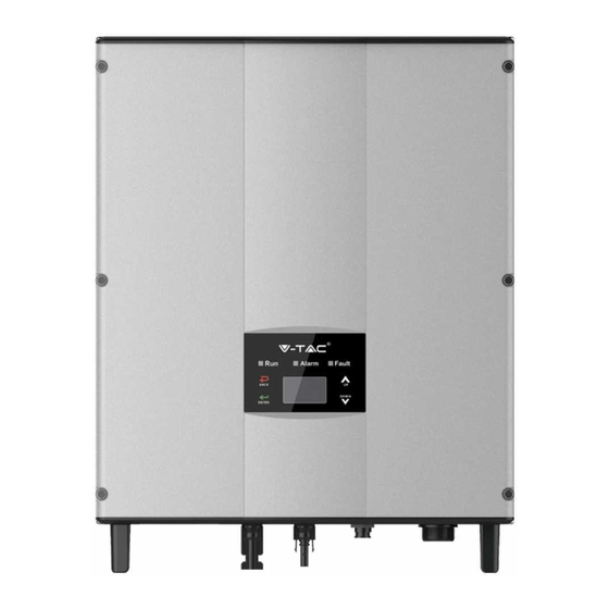
Page 6: Product Appearance
The recommended solar modules need to comply with IEC61730 Class A standard. SAFETY GUIDELINES The series grid-tied solar inverters support TN-S, TN-C, TN-C-S and TT grid connection. When applied to the TT connection, the N-to-PE voltage should be less than 30V. PRODUCT APPEARANCE Figure 3 Products appearance... - Page 7 PARTS INSTRUCTION N o . N a m e Ins t ruc t io n Co ver LED display panel LED indicato rs DC switch On –o ff o f the DC input (o ptio nal) DC input po rt Fo r the co nnectio n o f so lar mo dules A C terminal Fo r the co nnectio n o f A C o utput...
-
Page 8: Products Modules
ICONS CERTIFICATION Icons Instruction EU WEEE mark. Cannot dispose of the inverter as household waste. CE certification mark. The inverter complies with the CE directive. PRODUCTS MODULES Table of the grid-tied solar inverter Rated output Product name Model power Single-phase (L, N, PE) Single-phase grid-tied solar inverter... -
Page 9: Dimensions And Weight
DIMENSIONS AND WEIGHT Figure 5 Inverter dimensions Table of inverter dimension and net weight Net weight Model H (mm) D (mm) (mm) (kg) 3KW-2M / 5kW-2M Figure 6 Paper packages dimension Table of packages dimension and gross weight Gross Packagin weight Model (mm) -
Page 10: Installation
STORAGE If the inverter is not put into use immediately, the storage of inverter should meet the following requirements: • Do not remove the outer packing. • The inverter needs to be stored in a clean and dry place, and prevent the erosion of dust and water vapor. -
Page 11: Before Installation
Table of detailed delivery list of single-phase inverter N A M E Q UA N T IT Y 3KW-2M / 5KW-2M Installatio n bracket Operatio n manual B o lt M 5*20 Expansio n bo lts M 6*60 3KW-2M / 5KW-2M Co mmunicatio n co nnecto r DC co nnecto r 3KW-2M / 5KW-2M:2 pairs... - Page 12 Figure 8 Installation space Ensure there is sufficient space for heat-releasing. In generally, below space requirement should be met: Table of detailed installation space M inim um c le a ra nc e Lateral 200mm To p 450mm B o tto m 450mm Figure 9 Installation position ...
-
Page 13: Cable Specification
CABLE SPECIFICATION In order to regulate and compatible with the inverter AC/DC connector or terminal block specifications, below requirements on the AC/DC cable connected to corresponding inverter should be fulfilled: Table of cable specifications D C s ide A C s ide M ini c ro s s - s e c t io na l M in c ro s s - M in c ro s s s e c t io na l... -
Page 14: Installation Of Single-Phase Inverter
INSTALLATION OF SINGLE-PHASE INVERTER Figure 10 Installation bracket Figure 11 Installation bracket of 0.75~3KW inverter of 4~6KW inverter Table of size of installation bracket Table of instruction of installation bracket N o . S t ruc t ure ins t ruc t io n Ins t a lla t io n ho le M o de l Installatio n ho leΦ... -
Page 15: Wiring Installation
WIRING INSTALLATION This section describes the electrical connection related content and related safety precautions. Figure 13 is the schematic diagram of the photovoltaic grid-connected system. Figure 13 PV grid-connected system diagram Electrical connection must be carried out by professional technicians as wrong operation may cause damage to the device, physical injuries or even death during system operation. - Page 16 WIRING INSTALLATION Figure 14 Connection between DC connector and solar modules Connection steps: (1) Lighting, short-circuit and other protection measures which meet the local electrical safety laws and regulations are needed before the AC connection. PV strings can be connected to inverter only after protection measures which conform to local electrical regulations are taken and the technical parameters in this manual are fulfilled.
- Page 17 (3) After the DC connector is connected, use a multimeter to measure the voltage of the DC input string, verify the polarity of the DC input cable, and ensure that the voltage of each string is within the allowable range of the inverter, as shown in Figure 15 (4) Connect the DC connector with the inverter and ensure tightly-fastened;...
- Page 18 OPERATION INSPECTION BEFORE OPERATION The following items must be checked strictly before running the PV grid-connected inverter (including but not limited to): (1) Ensure the installation site meet the requirement mentioned in installation pace for easy installation, removing, operation and maintenance; (2) Ensure the mechanical installation meet the requirement mentioned in table of installation pace;...
-
Page 19: Daily Maintenance
STOPPING When it is necessary to carry out power-off maintenance, inspection and fault elimination on the inverter, stop the inverter according to the following steps: (1) Disconnect the breaker on inverter public grid AC side; (2) Disconnect the integrated DC switch of the inverter; (3) Disconnect the circuit switch on PV string DC input side;... -
Page 20: Display Panel
MAINTENANCE GUIDE Clean the inverter Cleaning procedure is as follows: (1) Disconnect the input and output switches. (2) Wait ten minutes. (3) Use a soft brush or a vacuum cleaner to clean the surface and the inlet and outlet of the inverter. -
Page 21: Operation Panel
Inverter stand-by. The public grid fault(A001, A003, A004, A005or A006); Warn Recoverable Fault Yellow indicator blinks in every 0.5s, others off fault (1) Inverter stand-by. Temperature abnormal(E006); (2) Inverter stand-by. DC input fault (E001); Warn Yellow indicator keeps on, others off Fault Hardware or software fault (E003, E004, E005, E008, E009, E011, E013 or E015). -
Page 22: Functions Operation
All information is displayed on the LCD screen. The background illumination of LCD screen will go out to save power if there is not button operation in 15 seconds. But it can be activated by pressing any button. Press “ENT” to enter into the main interface if the background illumination is on, as shown in Figure 19. -
Page 23: Parameter Settings
HISTORY Press “ ” and “ ” in the main interface to H is to ry select “History”, and then press “ENT” to 2 01 2 / 0 1 / 0 5 1 1 : 3 2 : 1 6 view the parameters which is shown in A 0 05 : G ri d un de r fr eq Figure 21. -
Page 24: Lcd Menus
“Setup menu” can realize parameter setup shown in table of parameters setting. LCD MENUS:... - Page 25 Table 6-3 Parameters setting Setting item LCD display Instruction Enter into the interface and edit the data through “ ” or “ ”. And then R S 4 85 A dd re ss press “ENT” again to the next bit. RS485 0 01 Address...
- Page 26 Enter into the interface and edit the data through “ ” or “ ”. And then press “ENT” again to the next bit. After editing the four bits, press “ENT” to save the edition and press U se r Pa ss wo rd “ESC”...
- Page 27 Enter into the interface and edit the user period through “ ” or “ ”. And then press “ENT” again to the next bit. After editing, press “ENT” to save the edition and press “ESC” to U se r Pe ri od exit.
- Page 28 Input password 0000 Run Param UV Volt OV time UV time UF Freq OV Volt UF time Password is required when enter into ACUV Volt(phase volt) 184V the interface of “Run Param”. Get the password from the supplier if ACUV Time necessary.
- Page 29 Input Password 0000 Run Param UV volt 1 OV time 1 UV time 1 UF Freq 1 OV volt 1 UF time 1 ACUV Volt(phase volt) 115V ACUV Time 00.04s There are 2 protections under ACOV Volt(phase volt) 309V G83/G59(UK) and PEA(Thailand) ACOV Time standards, and there is only one 00.02s...
-
Page 30: System Information
SYSTEM INFORMATION Press “ ” and “ ” in the main interface to select “System Information”, and then press “ENT” to view the parameters which is shown in Figure 24. System Information Part No . Serial No . Soft Ver Figure 24 System information The system information include “product model”, “serial No.”, “software version”... -
Page 31: Grid Certification Choice
Table of inverter control Control item LCD display Instruction Control the “On/Off” through the panel. O n / O ff C tr l Press “ ” and “ ” in the control On/Off control O FF interface to select the operation. Press “ENT”... - Page 32 After finish the country setting, please follow the user manual required with the proper use of inverter. Comparison Table: Available countries and their grid certification Country Certification Remark Germany VDE0126& AR-N4105 G83/G59 Australia AS4777 Greece VDE0126 Denmark TF3.2.1 Holland C10/C11 China Thailand Other...
-
Page 33: Monitoring Communication
MONITORING COMMUNICATION This chapter describes the communication connection of inverter and monitoring system (Industrial master, private computers, smart phones and so on). The standard communication mode of grid-tied solar inverter is RS485 which includes “RS485-M” and “RS485-S” ports. The RS485-M ports can communicate with private computers, smart phones and so on. -
Page 34: Connection Steps
Figure 29 RS485 pin on inverter Figure 30 Communication connector CONNECTION STEPS: (1) Connect the communication connector configured for the inverter to the RS485 terminal of the inverter, as shown in Fig b; Figure 31 Detailed connectiona (2) According to the table of Optional communication accessories, connect the commu- nication connector pinout and the user's device, make sure the connection is correct. -
Page 35: Troubleshooting
TROUBLESHOOTING Table of Fault code Fault code Message Instruction Fault analysis PV1 undervoltage A001 Input UV Input undervoltage PV2 undervoltage A002 Bus UV Bus undervoltage DC input A003 Grid UV AC undervoltage Low voltage of the public grid A004 Grid OV AC overvoltage High voltage of the public grid A005... -
Page 36: Technical Parameters
Output short- E015 OutputShort Output short-circuit circuit E018 Input OC Input overcurrent DC input overcurrent Inconsistent grid voltage, Data consistency E019 Incnst frequency, leakage current or fault AC/DC injection E020 PowerReversed DC power reversed DC power reversed The communication between Power meter Meter smart meter and inverter is faulty... - Page 37 Single-phase M o del 3kW-2M 5kW-2M M ax. DC vo ltage (V) Starting vo ltage (V) 1 20 1 20 M P P T vo ltage(V) 1 25-550 1 25-550 Operatio n vo ltage (V) 1 80-500 250-500 M P P T/strings per M P P T Input(DC) 5000 3000...
Need help?
Do you have a question about the VT-6603105 and is the answer not in the manual?
Questions and answers