Advertisement
Quick Links
SOLAR INVERTER WITH LCD DISPLAY &
Thank you for selecting and buying V-TAC Product. V-TAC will serve you
the best. Please read these instructions carefully & keep this user manual
handy for future reference. If you have any another query, please contact
our dealer or local vendor from whom you have purchased the product.
They are trained and ready to serve you at the best.
IN CASE OF ANY QUERY/ISSUE WITH THE PRODUCT, PLEASE REACH OUT TO US AT: SUPPORT@V-TAC.EU
FOR MORE PRODUCTS RANGE, INQUIRY PLEASE CONTACT OUR DISTRIBUTOR OR NEAREST
DEALERS. V-TAC EUROPE LTD. BULGARIA, PLOVDIV 4000, BUL.L.KARAVELOW 9B
INSTRUCTION MANUAL
DC SWITCH -THREE PHASE
INTRODUCTION
Multi-Language Manual QR CODE
Please scan the QR code to access the manual
in multiple languages.
5
*
WARRANTY
Advertisement

Subscribe to Our Youtube Channel
Related Manuals for V-TAC VT-6605305


Summary of Contents for V-TAC VT-6605305
- Page 1 Please scan the QR code to access the manual in multiple languages. IN CASE OF ANY QUERY/ISSUE WITH THE PRODUCT, PLEASE REACH OUT TO US AT: SUPPORT@V-TAC.EU FOR MORE PRODUCTS RANGE, INQUIRY PLEASE CONTACT OUR DISTRIBUTOR OR NEAREST DEALERS. V-TAC EUROPE LTD. BULGARIA, PLOVDIV 4000, BUL.L.KARAVELOW 9B...
- Page 2 WARNING 1. Please make sure to turn off the power before starting the installation. 2. Installation must be performed by a qualified electrician. 3. Proper grounding should be ensured throughout the installation. This marking indicates that this Caution, risk of product should not be disposed electric shock.
- Page 3 SAFETY GUIDELINES After receiving this product, first ma ke sure that the product is well packaged. If you have any questions, please contact the shipping company or local distributor immediately. Installation of PV inverters must be performed by professional technician who has been specially trained, thoroughly read and familiar with all the contents of this manual and familiar with the safety requirements of the electrical system.
- Page 4 WHAT TO DO AFTER SCRAPPING Do not dispose of the inverter together with household waste. The user has the responsibility and obligation to send it to the designated organization for recycling and disposal. DELIVERY AND INSTALLATION Keep the package and unit complete, dry and clean during storage and ...
- Page 5 MAINTENANCE AND INSPECTION Only qualified electricians are allowed to perform the mainte- nance, inspection, and components replacement of the inverter. Contact with the local dealer or supplier for maintenance. In order to avoid irrelevant personnel from entering the mainte- ...
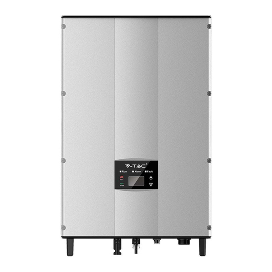
- Page 6 The recommended solar modules need to comply with IEC61730 Class A standard. SUPPORTED GRID CONNECTION STRUCTURE The series grid-tied solar inverters support TN-S, TN-C, TN-C-S and TT grid connection. When applied to the TT connection, the N-to-PE voltage should be less than 30V. Figure 2 Type of grid PRODUCT APPEARANCE Figure 3 Products appearance...
- Page 7 PARTS INSTRUCTION Na me Instruc tion Cover Operational panel LED status light, LCD display, keypad DC switc h On–off of the DC input (optional) DC input port For the c onnec tion of solar modules Communic ation port RS485 and EXT c ommunic ation port AC terminal For the c onnec tion of AC output Cooling chamber...
- Page 8 ICONS CERTIFICATION Icons Instruction EU WEEE mark. Cannot dispose of the inverter as household waste. CE certification mark. The inverter complies with the CE directive. PRODUCTS MODULES Table of the grid-tied solar inverter Product name Model Rated output power (W) Three-phase (L1,L2,L3,N,PE) Three-phase grid-tied solar inverter 4000...
- Page 9 DIMENSIONS AND WEIGHT Figure 5 Inverter dimensions Table of inverter dimension and net weight Model H (mm) W (mm) D (mm) Net weight (kg) 8kW / 10kW Figure 6 Paper packages dimension Table of packages dimension and gross weight Weight Packaging Model H (mm)
- Page 10 STORAGE If the inverter is not put into use immediately, the storage of inverter should meet the following requirements: • Do not remove the outer packing. • The inverter needs to be stored in a clean and dry place, and prevent the erosion of dust and water vapor.
- Page 11 Table of detailed delivery list of single-phase inverter Na me Q ua ntity 5kW / 8kW / 10kW inverter Installation brac ket Operation manual Assembling bolts M5*20 Expansion bolts M6*50 Communic ation c onnec tor DC c onnec tor 2 pairs / 1 pair(4kW- S、5kW- S) AC c onnec tor BEFORE INSTALLATION Installation tools...
- Page 12 (2) The installation site must be well ventilated and away from raindrops or direct sunlight. (3) There must be enough pre-reserved space around the installation site for convenient disassemble of the inverter and air convection Figure 8 Installation space (4) The ambient temperature of installation should be -25°C~60°C. (5) The installation site should be away from electronic devices which can generate strong electromagnetic interference.
- Page 13 CABLE SPECIFICATION In order to regulate and compatible with the inverter AC/DC connector or terminal block specifications, below requirements on the AC/DC cable connected to corresponding inverter should be fulfilled: Table of cable specifications DC side AC side Min cross section Min cross-section Min cross section Inverter model...
- Page 14 Table of size of installation bracket Spacing of installation hole Inverter model A(mm)*B(mm) 260*45 8kW / 10kW The procedures for installation of inverter are listed below: (1) Use the punch positioning plate in the packaging box to determine the punch position. As shown in Figure 10 Level the holes with a level ruler and mark it with a marking pen.
- Page 15 (4) Fix the installation bracket onto the expansion bolts and ensure the installation is firm enough(tightening torque is 13N•m) . As shown in Figure Figure 13 Fix the installation bracket (5) Hang the inverter onto the installation bracket and ensure the installation is firm enough.
- Page 16 WIRING INSTALLATION This section presents the detailed contents and safety precautions related to electrical connection. Fig 16 is the connection diagram for PV grid-connected system. Figure 16 PV grid-connected system diagram Electrical connection must be carried out by professional technicians as wrong operation may cause damage to the device, physical injuries or even death during system operation.
- Page 17 WIRING INSTALLATION Figure 17 MC4 DC connector and PV string connection The procedures for connecting PV string t to the inverter DC input are shown below: (1) Before connecting PV string to inverter, ensure proper measures against lightening and short circuit have been taken; ...
- Page 18 (4) Connect PV string to the inverter and ensure tightly-fastened (5) When removing the DC connector from the inverter, insert the head of the straight screwdriver into the raised hole in the middle of the connector, and force the movable end of the connector to exit.
- Page 19 OPERATION INSPECTION BEFORE OPERATION The following items must be checked strictly before running the PV grid-connected inverter (including but not limited to the following items): (1) Ensure the installation site meet the requirement mentioned in “before installation” for easy installation, removing, operation and maintenance. (2) Ensure the mechanical installation meet the requirement.
- Page 20 STOPPING When it is necessary to carry out power-off maintenance, inspection and fault elimination on the inverter, stop the inverter according to the following steps: (1) Disconnect the breaker on inverter public grid AC side; (2) Disconnect the integrated DC switch of the inverter; (3) Disconnect the switch on PV string DC input side;...
- Page 21 MAINTENANCE GUIDE CLEAN THE INVERTER Cleaning procedure is as follows: (1) Disconnect the input and output switches. (2) Wait ten minutes. (3) Clean the surface and air inlet/outlet of the inverter with soft brush or vacuum cleaner; (4) Repeat inspection before operation - operating content. (5) Restart the inverter.
- Page 22 (5) Clean the inverter cooling bin and fan with soft brush or vacuum cleaner. (6) Install the screws and covers of cooling bin or fan box to their original place. (7) Install the inverter to its original place again according to section installation. (8) Repeat the operations in section inspection before operation.
- Page 23 DISPLAY AND OPERATION PANEL This chapter describes the panel displaying and how to operate on the panel, which involves the LCD display, LED indicators and operation panel. LED INDICATORS There are three LED indicators on the panel: (1) “Run”, operation indicator, green; (2) “Warn”...
- Page 24 Inverter stand-by. The public grid fault(A001, A003, Warn A004, A005or A006); Fault Yellow indicator blinks in every 0.5s, others off fault (1) Inverter stand-by. Temperature abnormal(E006); (2) Recoverable Inverter stand-by. DC input fault Warn (E001); Fault Yellow indicator keeps on, others off Hardware or software fault (E003, E004, E005, E008, E009, E011, E013 or E015).
- Page 25 All information is displayed on the LCD screen. The background illumination of LCD screen will go out to save power if there is not button operation in 15 seconds. But it can be activated by pressing any button. Press “ENT” to enter into the main interface if the background illumination is on.
- Page 26 HISTORY Press “ ” and “ ” in the main interface to select “History”, and then press “ENT” to view the parameters which is shown in Figure 27. H is to ry 2 01 2 / 0 1 / 0 5 1 1 : 3 2 : 1 6 A 0 05 : G ri d un de r fr eq Figure 27 History parameters “Historical record”...
- Page 27 “Setup menu” can realize parameter setup shown in table of parameters setting. LCD MENUS:...
- Page 28 Table 6-3 Parameters setting Setting item LCD display Instruction Enter into the interface and edit the data through “ ” or “ ”. And then R S 4 85 A dd re ss press “ENT” again to the next bit. RS485 0 01 Address...
- Page 29 Enter into the interface and edit the data through “ ” or “ ”. And then press “ENT” again to the next bit. After editing the four bits, press “ENT” to save the edition and press U se r Pa ss wo rd “ESC”...
- Page 30 Enter into the interface and edit the user period through “ ” or “ ”. And then press “ENT” again to the next bit. After editing, press “ENT” to save the edition and press “ESC” to U se r Pe ri od exit.
- Page 31 Input password 0000 Run Param UV Volt OV time UV time UF Freq OV Volt UF time Password is required when enter into ACUV Volt(phase volt) 184V the interface of “Run Param”. Get the password from the supplier if ACUV Time necessary.
- Page 32 Input Password 0000 Run Param UV volt 1 OV time 1 UV time 1 UF Freq 1 OV volt 1 UF time 1 ACUV Volt(phase volt) 115V ACUV Time 00.04s There are 2 protections under ACOV Volt(phase volt) 309V G83/G59(UK) and PEA(Thailand) ACOV Time standards, and there is only one 00.02s...
- Page 33 SYSTEM INFORMATION Press “ ” and “ ” in the main interface to select “System Information”, and then press “ENT” to view the parameters which is shown in Figure 30. System Information Part No . Serial No . Soft Ver Figure 30 System information The system information include “product model”, “serial No.”, “software version”...
- Page 34 Table of inverter control Control item LCD display Instruction Control the “On/Off” through the panel. O n / O ff C tr l Press “ ” and “ ” in the control On/Off O FF control interface to select the operation. Press “ENT”...
- Page 35 Reference Table: Grid certification and grid voltage and frequency of some countries...
- Page 36 Australia AS4777.2&AS4777.3 Singapore 400~415V 50Hz AS/NZS3100 New Zealand Belgium Luxembourg C10/C11 380~400V 50Hz Holland Denmark TF3.2.1 380~400V 50Hz Thailand 380V 50Hz China CGC/CF001 380V 50Hz Italy ENEL 400V 50Hz The user can change the country setting through the following ways: LCD screen:MENU→Main Menu: Setup→Setup Menu: Country→Country: V - p v 1 : 0 00 .
- Page 37 MONITORING COMMUNICATION This chapter describes the communication connection of inverter and monitoring system (Industrial master, private computers, smart phones and so on). The standard communication mode of grid-tied solar inverter is RS485 which includes “RS485-M” and “RS485-S” ports. The RS485-M ports can communicate with private computers, smart phones and so on.
- Page 38 Figure 35 RS485 pin on inverter Figure 36 Communication connector CONNECTION STEPS: (1) Connect the communication connector configured for the inverter to the RS485 terminal of the inverter, as shown in Fig 37; Figure 37 Detailed connectiona (2) According to the table of Optional communication accessories, connect the communica- tion connector pinout and the user's device, make sure the connection is correct.
- Page 39 TROUBLESHOOTING Table of0 Fault code Fault Message Instruction Fault analysis code PV1 undervoltage A001 Input UV Input undervoltage PV2 undervoltage A002 Bus UV Bus undervoltage DC input A003 Grid UV AC undervoltage Low voltage of the public grid A004 Grid OV AC overvoltage High voltage of the public grid A005...
- Page 40 DRM0 Loss (this error code only available connected under AS4777 safety) TECHNICAL PARAMETERS Table of technical parameters Three-phase Model VT-6605305 VT-6608305 VT-6610305 Max. DC volt age (V) 1000 1000 St art ing volt age (V) MPPT volt age range(V) 200-800...
- Page 41 Rat ed out put power(W) 5000 8000 10000 320~460Vac, 50Hz(47~51.5Hz) / 60Hz(57~61.5Hz) Volt age(V)/ f requency(Hz) range Maximum out put current (A) 12.8 16.1 265A @ 34ms Maximum out put f ault current Output (AC ) Less t han 10 A AC inrush current Maximum out put overcurrent 15.8...
Need help?
Do you have a question about the VT-6605305 and is the answer not in the manual?
Questions and answers